Design and Implementation of an IEEE 802.15.3-based Ultra-Wideband MAC Controller
7
0
0
全文
(2) Int. Computer Symposium, Dec. 15-17, 2004, Taipei, Taiwan.. The rest of the paper is organized as follows. Section 2 describes the related work. Section 3 presents the system architecture of the 802.15.3based UWB MAC. The prototype implementation and evaluation are described in Section 4. Finally, we conclude in Section 5.. allocation information to the piconet. Notably, each piconet is an ad-hoc, peer-to-peer wireless communication network, as shown in Figure 1.. 2. Related Work 2.1 UWB UWB has been around since the 1980s and is mainly used by the military in the field of radar applications. However, with the dramatic progress of wireless communication technology, UWB is becoming the most attractive candidate for low cost consumer communication applications, e.g., the wireless home entertainment and mobile multimedia products. The UWB systems are mostly based on the Impulse Radio (IR) technology that are typically implemented in a carrier-less fashion, in contrast to the Radio Frequency (RF) technology adopted in conventional narrowband and wideband systems. Because it utilizes extremely short pulse that results in a wide spectral waveform occupying several GHz of bandwidth, the term Ultra-Wideband (UWB) is used [5]. Due to its impulse radio nature, UWB offers some distinguished advantages compared to other communication technologies, including lower power, low cost, low interference levels to existing services, mitigated multi-path fading effects, high data rates, and precise positioning/locating ability.. Figure 1. IEEE 802.15.3 Piconet. Figure 2. IEEE 802.15.3 Superframe Timing in the IEEE 802.15.3 is based on the superframe, which is shown in Figure 2. Each superframe is comprised of three main sections: beacon, the optional Contention Access Period (CAP), and the Channel Time Allocation Period (CTAP). The beacon is sent by the PNC at the beginning of every superframe. It is used for timesynchronization, for broadcasting the timing allocation, and for communicating management information for the piconets. Following the beacon is the CAP period. The CAP is used to communicate commands and non-stream asynchronous data. By following the CSMA/CA protocol, each DEV can try to transmit data in CAP. The last period is CTAP, which is a TDMA-based access period. IEEE 802.15.3 divides the CTAP into a number of channel time allocation (CTA) slots and MCTAs (Management CTAs). Note that MCTAs are a kind of CTAs that are reserved by the PNC for PNCdevice communication. Each node can transmit data in CTAP if, and only if, the PNC has allocated time slots for it. If a device has great amount of data or has streaming requests from applications, it should send requests to the PNC in the CAP period. The PNC then checks the bandwidth status and the number of unused slots to decide whether the request should be granted or not.. 2.2 IEEE 802.15.3 IEEE 802.15.3 aims to publish a new standard for high data rate (20 Mbits/sec or higher) wireless PAN. In addition, it also provides the Quality of Services (QoS) isochronous protocol, lower power, and low cost solution to meet the demanding requirements of portable consumer digital image and multimedia applications. Since the IEEE 802.15.3’s characteristics matches the application needs of UWB, IEEE 802.15.3a thus aims to define a physical layer standard, based on UWB, to pace with IEEE 802.15.3 MAC for a UWB communication system. In the following, we briefly present the IEEE 802.15.3 MAC protocol. IEEE 802.15.3 MAC is a TDMA-based Medium Access Controller (MAC) for a Wireless PAN. The IEEE 802.15.3 devices communicate with each other in small area networks named piconet. A piconet consists of one or more devices (DEVs) and one of the DEVs is selected as the piconet coordinator (PNC). Thus, IEEE 802.15.3 MAC protocol is centralized coordinated. The PNC provides the basic network timing synchronization, Quality of Service (QoS) requirements, power save modes and timing. 3. System Architecture. 332.
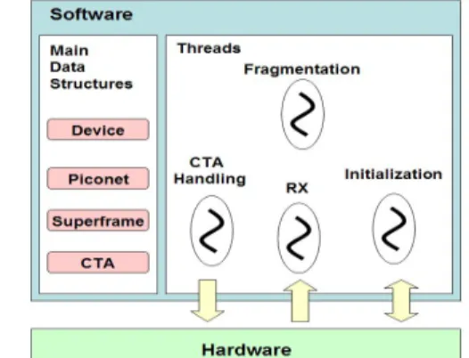
(3) Int. Computer Symposium, Dec. 15-17, 2004, Taipei, Taiwan.. In this section, we present the software and hardware architectures of our IEEE 802.15.3-based UWB MAC.. accepts user commands and reports the current system status to the user through the GUI. RX thread. This thread is responsible for moving data from the hardware buffer into a system-wide software buffer (i.e., rx_main_buffer) to prevent the overflow of the former. CTA handling thread. This thread handles the frame transceiving. Each CTA has a corresponding queue for frame transmission. Before the starting of each CTA, this thread will check to see whether or not the device is the source node of the CTA (according to the CTA structure). If it is, the thread will send the data residing in the corresponding queue to the hardware buffer. For data receiving, this thread will get frame data from the rx_main_buffer. If the receiving frame is a command, the thread will handle it directly. Otherwise (i.e., a data frame), the thread will hand the data to the fragmentation thread for frame reassembly. In addition, this thread is also responsible for generating beacons according to the piconet, superframe, and CTA structures if the device is a PNC. Fragmentation thread. For outgoing data, this thread will divide it into frames (with maximum size of 2048 bytes), and then insert the frames into the queue that corresponds to the CTA. Besides, this thread is also responsible for reassembling incoming frames and handing the resulting data to the user.. 3.1 System Overview The same as IEEE 802.15.3, the channel time management of our system is based on superframe, which is shown in Figure 3. It differs from the IEEE 802.15.3 specification in two aspects. First, we removed the Contention Access Period (CAP). As mentioned above, the low emission energy of UWB has made CSMA/CA become ineffective. Secondly, we add an ACTA period for transmitting channel time requests (i.e., CTRq). This reduces the possibility of packet collisions for the CTRq. Other kinds of PNC-device data can be transmitted in open MCTA. Note that the medium access control mechanism used in ACTA and open MCTA is the slotted aloha, while the other periods are based on TDMA.. Figure. 3 Superframe of Our UWB System The implementation of the system consists of both the software and the hardware parts. The former is responsible for implementing most of the IEEE 802.15.3 protocol, while the latter implements the TDMA functionality and the data movement mechanism.. 3.2 Software Architecture As mentioned before, the UWB MAC is mainly implemented in software, which contains four major data structures and four threads as shown in Figure 4. The device structure records the device identifier, the MAC address, and the other information specific to this device. The piconet structure records the piconet identifier, BSID, MAC address of the PNC, and the channel used by this piconet. The superframe structure is used to store the information about the current superframe, such as superframe duration and current superframe identifier. The CTA structure contains all the information of each CTA, including the starting time and duration of the CTA, the source and the destination nodes, etc. These data structures are used by the following four threads to implement the UWB MAC protocol. Initialization thread. This thread is used to initialize the hardware part of the system. After the initialization, it will create the remaining three threads. And then, it will handle the GUI task that. Figure 4. The Software Data Structures and Threads. 3.3 Hardware Architecture Figure 5 shows the hardware architecture of our UWB system. It consists of three components: Host Interface, Control Unit, and FIFO. The Host Interface component is the interface between the hardware and software (i.e., host) parts. Specifically, the software part communicates with the hardware by sending and receiving data packets through the Host interface. In addition to the data packets, other traffics such as register access are also passed through this interface.. 333.
(4) Int. Computer Symposium, Dec. 15-17, 2004, Taipei, Taiwan.. Different from the Tx packet store, the Rx packet store is not partitioned since the hardware does not need to parse the received packet at all. The parsing is left to the software part. Therefore, we do not partition the Rx packet store.. Figure 5. Hardware Architecture of the UWB System Control Unit is the major component of the hardware part. It has two functions, TDMA (Time Division Multiple Access) and DMA (Direct Memory Access). For the TDMA function, it controls when to enable Tx/Rx according to the CTA information that is given by the UWB software. For the DMA function, it moves data between the Host Interface component (or the FIFO component) and the SRAM. When the host software wants to send a packet, the packet will be written to the SRAM first. Once the corresponding CTA begins, the Control Unit will turn on Tx and make the in-SRAM packet data be sent out through the FIFO component. On the other hand, when the FIFO receives a packet, it stores the packet into the SRAM first. And then, the software part will eventually get the packet data through the Host Interface component. The FIFO component is used for packet transmission and reception. It performs CRC jobs such as appending CRC words and doing CRC checks. In addition, it is responsible for sending immediate ACKs for the received packets.. Figure 6. Packet Store Partitions 3.3.2 System Registers The system registers allow the software part to issue commands to the hardware or get status information from the hardware. These registers can be divided into the following four categories. DEVID Control/Status Registers DEVID_WRITE: This is used by the software part to write the device identifier into the hardware. DEVID_READ: This is used to get the current device identifier. CTA Control/Status Registers CURRENT_CTA_TYPE_READ: This allows the software part to learn the current period in a superframe. Possible return values can be Tx_Beacon, Tx_CTRq, Tx_Command, Tx_Association, Tx_Data, Rx_Any, and NULL. For example, Tx_Beacon will be returned if the hardware is transmitting a beacon. If the hardware is not transmitting or receiving any packets, NULL will be returned.. 3.3.1 Packet Store Partitioning As we mentioned above, a superframe in our system can be divided into beacon duration, ACTA, MCTA, and CTA. In the beacon duration, PNC is responsible for broadcasting the beacon packet to all the devices in the piconet. In ACTA, channel time requests packets (i.e., CTRq) can be sent. Association requests and other command packets are sent during the MCTA periods. And, CTA periods are responsible for transmitting data packets. Since different kinds of packets should be sent in different periods, we divide the Tx packet store (in SRAM) into several partitions. Figure 6 shows the partitioning. This allows the hardware to get rid of parsing the packet type before sending a packet, and hence reduce the hardware complexity. For example, when a superframe begins, the hardware of a PNC device can just sends the packet starting from address 00000. It does not need to scan the whole Tx packet store to find out where the beacon is.. CTA_START_WRITE, CTA_END_TIME_WRITE, CTA_TYPE_WRITE: These are used by the software to set the information of a particular CTA. The information includes the starting time, the end time, and the type of the CTA. The CTA type can be ACTA, MCTA, CTA Tx, or CTA Rx. CTA_REGISTER_STATE: This is used to get all the CTA information that is currently set in the hardware.. 334.
(5) Int. Computer Symposium, Dec. 15-17, 2004, Taipei, Taiwan.. Packet Store Status Registers RX_ANY_SIZE_READ, TX_BEACON_SIZE_READ, TX_CTRQ_SIZE_READ, TX_ASSOCIATION_SIZE_READ, TX_COMMAND_SIZE_READ, TX_DATA_SIZE_READ: These are used to get the available space of a particular partition. With this information, the software part can tell whether or not it should send more packets to the hardware Tx packet store. It can also tell whether or not it should receive packets faster from the Rx packet store.. Figure 8. Connection between Host Interface and Control Unit. Superframe Control Register SUPERFRAME_DURATION: This is used to notify the hardware the length of a superframe. With this information, the hardware can send beacons periodically.. For data receiving, the software part has to ask the Control Unit the number of data bytes in the SRAM before issuing a read operation. This can prevent blocking on the data receiving.. 3.3.3 Host Interface. 3.3.4 Control Unit. As we mentioned above, the Host Interface component is the interface between the hardware and software (i.e., host) parts. The data transmitting between the software part and the Host interface is divided into capsules, each of which contains a maximum number of 15 data words (i.e., each word is 16 bit wide). The software part should attach a header before each capsule. Figure 7 shows the format of the header. The type field indicates the type of the data (e.g., beacon, data). If the capsule is used for setting a system register, the parameter field will contain the new value of the register. Otherwise, it will be empty. And, the size field indicates the number of data words in this capsule. After getting a whole capsule, the Host Interface issues a request (together with the header) to the Control Unit, which will raise the transmit_ok signal when it has setup the SRAM to receive the data. Once the transmit_ok signal is raised, the Host Interface will write the data words to the SRAM. Figure 8 shows the connection between the Host Interface and the Control Unit.. Figure 9. Block Diagram of the Control Unit Figure 9 shows the block diagram of the Control Unit component. As we mentioned before, the main functions of this component are TDMA and DMA. TDMA Implementation. When the software part writes the CTA information to the system registers, the information will be stored into the Control Register block. Each time a superframe starts, the Control Register block will send the start and end time of the first CTA to the Timer Center block. And, a timer clock (that will increase by 1 each us) is reset. When the clock reaches to the CTA start time, the OnTime signal is turned on. Once the end time is reached, the signal is turned off. This enables the other logic circuit to perform actions according to the starting and the ending of a CTA. For example, the FIFO component will turn on its Tx or Rx according to the OnTime signal. Note that when the end time is reached, the Expire signal will become active. This notifies the Control Register. Figure 7. The Capsule Header. 335.
(6) Int. Computer Symposium, Dec. 15-17, 2004, Taipei, Taiwan.. block to send the information about the next CTA to the Timer Center. DMA Implementation. Both the Host Interface and the FIFO components issue DMA requests to the Control Unit if they have data that needs to be sent to the SRAM-based packet store. The DMA requests are received by the DMA Request Arbiter, which prioritizes the requests. The highest priority requests will be granted and passed to the DMA block, which sets up the SRAM and activates the chip-select signal of the corresponding component so as to allow the component to read/write the SRAM.. 4. Implementation Evaluation. and. Prototype. 4.1 Implementation This section presents the implementation environment and performance evaluation of the IEEE 802.15.3-based UWB MAC. As described in Section 3, the MAC system is divided into software and hardware parts. The former is implemented in C and running on a host computer. The latter is implemented in a Xilinx Virtex-II FPGA on the BenADDA board, which is plugged by the Nallatech BenOne [11] development motherboard. The BenOne board can be connected by a host computer via the PCI or USB interface. Following shows the specification of BenOne and BenADDA boards respectively.. 3.3.5 FIFO. Motherboard – (BenOne card) z Supports one DIME-II slot for an DIME-II Module z Spartan 2 FPGA for 3.3/5V PCI or USB interface z Host interfacing via 3.3V/5V PCI 32-bit/33MHz or USB v1.0 interface Daughter Board - (BenADDA module) Xilinx Virtex-II user FPGA: XC2V20004FG456 ( 2 million gates ) z 2 ADC channels: AD664 ADC z 2 DAC channels: AD9772 DAC z One bank of ZBT-SSRAM (133Mhz, 256K*16 bits). Figure 10. Block Diagram of the FIFO Component. z. Figure 10 shows the block diagram of the FIFO Component. The major functionality of it is to perform CRC32 jobs and to acknowledge the received packets. When transmitting a packet, the FIFO component will append the CRC32 information to the end of the packet. When receiving a packet, it will verify if the CRC32 result is correct. If it is, the packet will be written to the SRAM (through DMA). Otherwise, the packet will be dropped. Once a packet is received, the FIFO component will parse the packet header to see if it is needed to acknowledge the packet immediately. If it is, the FIFO component will generate the ACK packet. The ACK packet will be sent out within the time of Short Inter-Frame Space (SIFS) after the receiving of the original packet. In addition to the above functionality, the FIFO component also helps the synchronization between the PNC and devices. Specifically, the FIFO component checks if a received packet is a beacon. If it is, the BeaconStart signal will be turned on in order to make the Control Unit component to reset the timer clock.. 4.2 Prototype Evaluation The code size of the software part is 208 Kbytes. The FPGA utilization of the hardware implementation is shown in Table 1. Table 2 presents the execution speed of the synthesized hardware. Since the hardware data bus is 16-bit wide, the maximal throughput achieved by the hardware is 50.055 x 16 (bits) = 800 Mbps. Table 1. FPGA utilization on the 2v2000fg676-6 Device Number of Slices 3108/10752 28% Number of Slice Flip Flops 3034/21504 14% Number of 4 input LUTs 5202/21504 24% Number of bonded IOBs 97/456 65% Number of TBUFs 48/5376 0% Number of GCLKs 2/16 12%. 336.
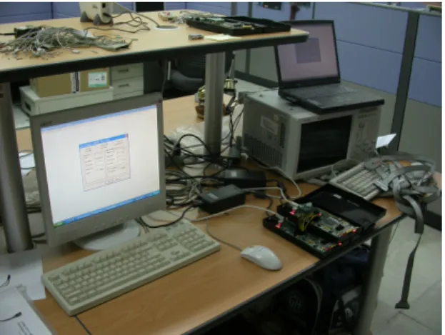
(7) Int. Computer Symposium, Dec. 15-17, 2004, Taipei, Taiwan.. To verify the functionality of the MAC, we developed a prototype on top of the Xilinx Virtex-II FPGA board. According to the evaluation results, the code size of the software is about 208 Kbytes, which makes it suitable to be used in embedded systems to satisfy the needs for pervasive computing. Moreover, the maximum throughput of the synthesized hardware code can reach 800Mbps, which shows that it is suitable as a high speed UWB MAC.. Table 2. Hardware Performance Result Minimum period 19.978ns Maximum Frequency 50.055MHz Minimum input arrival time before 5.632ns clock Maximum output required time after 9.008ns clock Maximum combinational path delay 6.560ns. 6. References. To demonstrate the effectiveness of our system, we use a desktop PC connected by a BenOne development board acting as the PNC. A notebook, which is also connected by a BenOne development board, acts as a DEV. Furthermore, the two development boards are connected by wires to emulate the wireless media. Figure 11 shows our prototype environment.. [1] Robert J. Fontana, et. al., “Recent Advances in Ultra Wideband Communication Systems,” Proceedings of IEEE Conference on Ultra Wideband Systems and Technologies, May 2002. [2] David G. Leeper, “A Long-Term View of ShortRange Wireless,” IEEE Computer Magazine, Vol. 34, No. 6, pp 39- 44, June 2001. [3] David G. Leeper, “Ultrawideband – The Next Step in Short-Range Wireless,” IEEE MTT-S International Conference on Microwave Symposium Digest, Vol. 1, pp. 357-360, 2003. [4] Woe Z. Win, Robert A. Scholtz, “Impulse Radio: How It Works,” IEEE Communications Letters, Vol. 2, No. 1, pp. 36-38, February 1998. [5] Jeff Foerster, Evan Green, Srinivasa Somayazulu, David Leeper, “Ultra-Wideband Technology for Shortor Medium-Range Wireless Communications,” Intel Technology Journals, May 2001. [6] IEEE P802.15.3™ Standard for Information technology – Telecommunications and information exchange between systems – local and metropolitan are networks – Specific requirements - Part 15.3: Wireless Medium Access Control (MAC) and Physical Layer (PHY) Specifications for High Rate Wireless Personal Area Networks (WPANs), September, 2003. [7] Freescale Semiconductor Inc., available at http://www.freescale.com, August 2004. [8] The U.C.A.N (Ultra-wideband Concepts for Adhoc Networks) Project, available at http://www.prorec-projekte.de/ucan/, April 2004. [9] IEEE 802.15 Working Group for WPAN: http://grouper.ieee.org/groups/802/15. [10] Domenico Porcino and Walter Hirt, “UltraWideband Radio Technology: Potential and Challenges Ahead,” IEEE Communication Magazine, pp. 66-74, July 2003. [11] Nallatect Ltd., “Benone Single-slot DIMEII Motherboard PCI Card”, available at http://www.nallatech.com/solutions/products/em bedded_systems/dime2/rc_systems/benone/, August 2004.. Figure 11. The Prototype Implementation Environment. 5. Conclusions UWB is an emerging and promising wireless communication technology for Personal Area Network (PAN). It not only enables short-range high speed communication, but also plays an important role in the realization of pervasive networking. IEEE 802.15.3 has defined a MAC for wireless PAN, which is regarded as the most appropriate candidate for high speed UWB MAC. However, the implementation of 802.15.3-based UWB MAC has not shown in the previous literatures. In this paper, we describe the design and implementation of an IEEE 802.15.3-based UWB MAC, which is developed by using the hardwaresoftware co-design approach. The major protocolprocessing tasks are done by the software, while the TDMA functionality and the data movement mechanism are implemented in the hardware.. 337.
(8)
數據


+2
相關文件
Microphone and 600 ohm line conduits shall be mechanically and electrically connected to receptacle boxes and electrically grounded to the audio system ground point.. Lines in
2.1.1 The pre-primary educator must have specialised knowledge about the characteristics of child development before they can be responsive to the needs of children, set
Reading Task 6: Genre Structure and Language Features. • Now let’s look at how language features (e.g. sentence patterns) are connected to the structure
Promote project learning, mathematical modeling, and problem-based learning to strengthen the ability to integrate and apply knowledge and skills, and make. calculated
Now, nearly all of the current flows through wire S since it has a much lower resistance than the light bulb. The light bulb does not glow because the current flowing through it
Then they work in groups of four to design a questionnaire on diets and eating habits based on the information they have collected from the internet and in Part A, and with
This kind of algorithm has also been a powerful tool for solving many other optimization problems, including symmetric cone complementarity problems [15, 16, 20–22], symmetric
Root the MRCT b T at its centroid r. There are at most two subtrees which contain more than n/3 nodes. Let a and b be the lowest vertices with at least n/3 descendants. For such
