國
立 交 通 大 學
電信工程學系碩士班
碩士論文
適用於具指向性天線與功率控制
無線隨意網路之跨層設計
Cross-Layer Design for Wireless Ad-hoc Networks
with Directional Antennas and Power Control
研 究 生:蕭昆苑 Student:
Kun-Yuan
Hsiao
指導教授:李大嵩 博士 Advisor:
Dr.
Ta-Sung
Lee
適用於具指向性天線與功率控制
無線隨意網路之跨層設計
Cross-Layer Design for Wireless Ad-hoc Networks
with Directional Antennas and Power Control
研 究 生:蕭昆苑 Student: Kun-Yuan Hsiao
指導教授:李大嵩 博士 Advisor:
Dr. Ta-Sung Lee
國立交通大學
電信工程學系碩士班
碩士論文
A Thesis
Submitted to Institute of Communication Engineering
College of Electrical Engineering and Computer Science
National Chiao Tung University
in Partial Fulfillment of the Requirements
for the Degree of
Master of Science
in
Communication Engineering
June 2005
Hsinchu, Taiwan, Republic of China
適用於具指向性天線與功率控制
無線隨意網路之跨層設計
學生:蕭昆苑
指導教授:李大嵩 博士
國立交通大學電信工程學系碩士班
摘要
無線隨意網路 (wireless ad hoc network) 是由多個可任意移動位置之行動主 機所組成,相較於有基礎結構之網路,無線隨意網路擁有較靈活之傳輸方式,然 而傳統使用全方向性天線之無線隨意網路傳輸易造成網路擁擠。將指向性天線應 用在無線隨意網路中能夠顯著地提升空間再使用的可能性而減緩網路擁擠程度, 進而提昇網路整體資料流量。為了能完全發揮指向性天線的特性,許多指向性媒 介接取控制 (directional medium access control) 協定被提出。然而這些指向性媒介 接取控制協定卻引起了新類型的隱藏節點 (hidden node) 和封鎖問題,導致資料流 量隨之下降。在本論文中,吾人針對使用指向性天線的實體、媒介接取控制與路 由協定提出一整合性的設計。吾人提出之M-null 指向性天線模型搭配指向性媒介 接 取 控 制 不 只 能 夠 指 向 性 地 傳 送 封 包 , 也 能 形 成 M 個 波 束 形 成 之 零 點 (beamforming null) 以消除來自其他方向的干擾。如此一來隨意節點不只能充份地 達到空間再使用,也能透過解決隱藏節點和封鎖問題而明顯地增加資料流量。此 外為了有效處理指向性天線強增益對遠方通訊之干擾,吾人提出了功率控制之跨 層設計。透過控制傳送功率,能使得在鄰近範圍內的二組或以上的節點可同時進 行資料傳輸,因而大大地提昇網路整體資料流量,此外也可降低功率消秏。最後, 相較於使用全向性天線和基本指向性天線的系統,吾人藉由電腦模擬驗證本論文 所提的系統架構可大幅度地改進網路的整體效能。
Cross-Layer Design for Wireless Ad-hoc Networks
with Directional Antennas and Power Control
Student: Kun-Yuan Hsiao
Advisor: Dr. Ta-Sung Lee
Institute of Communication Engineering
National Chiao Tung University
Abstract
A wireless ad hoc network is a collection of wireless mobile hosts that are dynamically and arbitrarily located in a certain area. Compared with infrastructure networks, ad hoc network has more flexible ways of communication. However, the conventional ad hoc network uses omnidirectional antennas, which may result in network congestion. Using directional antennas can increase the potential for spatial reuse to alleviate network congestion significantly, leading to higher total network throughput. In order to exploit the benefit of directional antenna, many directional MAC (DMAC) protocols are proposed. However, these DMAC protocols induce new types of hidden terminal and blocking problems, which decrease the network throughput performance drastically. In this thesis, we propose an integrated design of physical, MAC and routing protocols with the use of directional antennas. An M-null directional antenna model with DMAC is proposed to transmit packets directionally and form M beamforming nulls to eliminate interference from other direction. Therefore, ad hoc nodes can adequately achieve spatial reuse, and the throughput performance is improved significantly due to addressing the hidden terminal as well as blocking problems. Furthermore, to deal with the high directional antenna gain which may potentially interfere with communications taking place far away, we propose a cross-layer design of power control protocol. Through controlling transmission power, simultaneous data transmissions of two or more pairs of nodes located in each other’s vicinity may be allowed and thus the network total throughput is enhanced drastically. In addition, power consumption is reduced. Finally, we evaluate the performance of the proposed system architecture by computer simulations, and confirm that the throughput performance is improved greatly over omnidirectional and basic directional antenna communications in ad hoc networks.
Acknowledgement
I would like to express my deepest gratitude to my advisor, Dr. Ta-Sung Lee, for his enthusiastic guidance and great patience. I learn a lot from his positive attitude in many areas. Heartfelt thanks are also offered to all members in the Communication Signal Processing (CSP) Lab for their constant encouragement. Finally, I would like to show my sincere thanks to my parents and friends for their invaluable love.
Contents
Chinese Abstract
I
English Abstract
II
Acknowledgement III
Contents IV
List of Figures
VII
List of Tables
X
Acronym Glossary
XI
1 Introduction 1
2 Issues in Wireless Ad Hoc Networks
4
2.1 Medium Reservation... 4
2.1.1 Hidden Terminal Problem... 5
2.1.2 RTS/CTS Exchanging Mechanism ... 6
2.1.3 IEEE 802.11 DCF protocol... 7
2.1.4 Blocking Problem ... 9
2.2 Directional Antenna for Wireless Ad Hoc Networks...11
2.2.1 Classification of MAC Protocols for Directional Antenna Models...11
2.2.2 Problems of Existing Directional Medium Access Control (DMAC) Protocols ... 14
3 Performance Enhancement via Directional Antennas
25
3.1 System Architecture...26
3.2 Physical Layer: Directional Antennas...27
3.2.1 Features of Directional Antennas...27
3.2.2 Multiply Constrained Minimum Variance (MCMV) Beamforming....28
3.2.3 M-Null Directional Antennas Model ...30
3.3 MAC Layer: DMAC...32
3.3.1 Neighbor Node Location Identification...32
3.3.2 Modification of RTS/CTS Exchanging Mechanism...33
3.3.3 Directional Network Allocation Vector (DNAV)...34
3.4 Routing Layer ...36
3.4.1 Classification of Current Routing Protocols...37
3.4.2 Modification of Destination Sequence Distance Vector (DSDV) Routing Protocol ...39
3.4.2.1 Route Discovery ...41
3.4.2.2 Route Maintenance ...43
3.5 Operation of the Cross-Layer M-Null Directional Antenna System...44
3.6 Computer Simulations ...46
3.6.1 Nulling Operation Under 4-Node Topology ...47
3.6.2 Nulling Operation Under Random Topology ...48
3.6.3 Effect of Number of Beamforming Nulls ...49
3.6.4 Effect of Beamforming Null Angle Error ...50
4 DMAC with Cross-Layer Power Control for Wireless Ad Hoc
Networks
69
4.1 Power Scaling in DMAC Transmission...70
4.2 Operation of the Cross-Layer Power Control Protocol ...72
4.3 Computer Simulations ...73
4.3.1 Power Control Under 4-Node Topology...74
4.3.2 Power Control Under Random Topology ...75
4.4 Summary...77
5 Conclusion
83
List of Figures
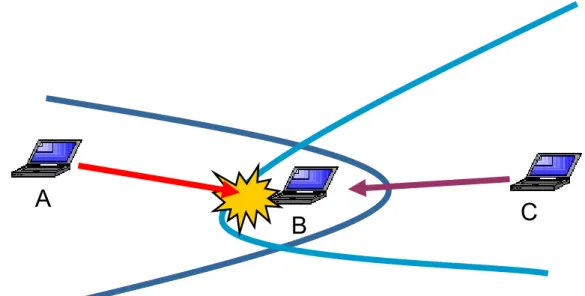
Figure 2.1 Hidden node problem: Node C is sending data packet to node B. Node A is out of radio range of node C, and thus is a hidden node. Collision occurs at node B when node A initiates transmission...20
Figure 2.2 Node B and node C do the RTS/CTS exchanging before data transmission. Node A and node D are blocked by RTS packet and CTS
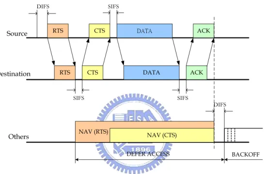
packet, respectively...20 Figure 2.3 Packet transmission timing based on IEEE 802.11 MAC protocol ...21 Figure 2.4 Blocking problem: Node A and node B are transmitting data packets. Only nodes in the gray area are required to be blocked. Node E and node G are unnecessarily blocked. This figure also shows how blocking problem propagates...22 Figure 2.5 The sectorized antennas model ...23 Figure 2.6 The switched beam antenna system...23 Figure 2.7 A topology used to demonstrate the hidden terminal and blocking
problems in existing MAC protocols...24
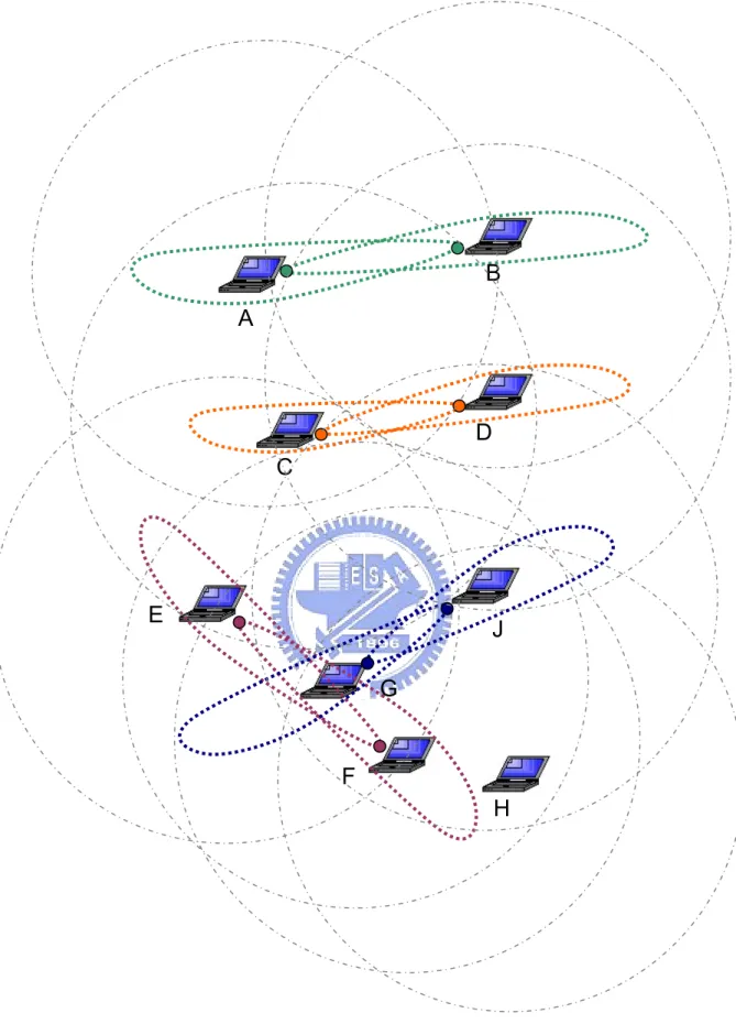
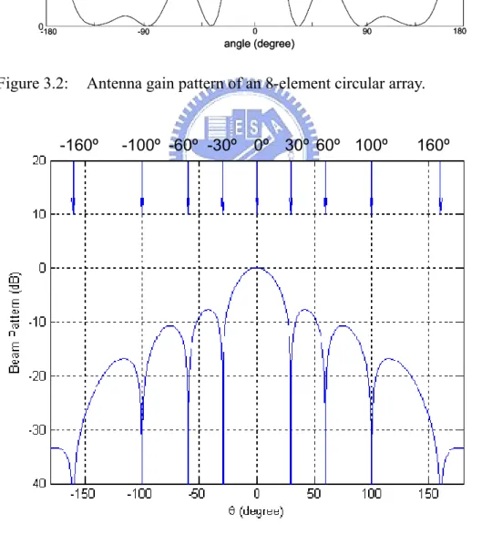
Figure 3.1 Network capacity is improved via directional antennas. Four sessions is allowed to be held simultaneously without interfering with each other. While in the case of omni-directional communication, most nodes are blocked...53 Figure 3.2 Antenna gain pattern of an 8-element circular array ...54 Figure 3.3 The antenna gain pattern (dB) of an 9-elements MCMV beamforming can form one main beam towards 0° and eight beamforming nulls in ±30°, ±60°, ±100°, ±160°...54
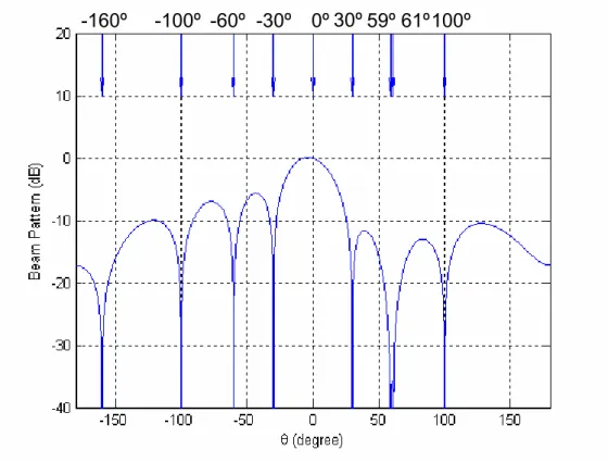
Figure 3.4 The antenna gain pattern (dB) of an 9-element MCMV beamforming can form one main beam towards 0° and eight beamforming nulls in ±30°, -60°, 59˚, 61˚, ±100°, −160° ...55 Figure 3.5 A 7-element electronically steerable passive array radiator antenna.
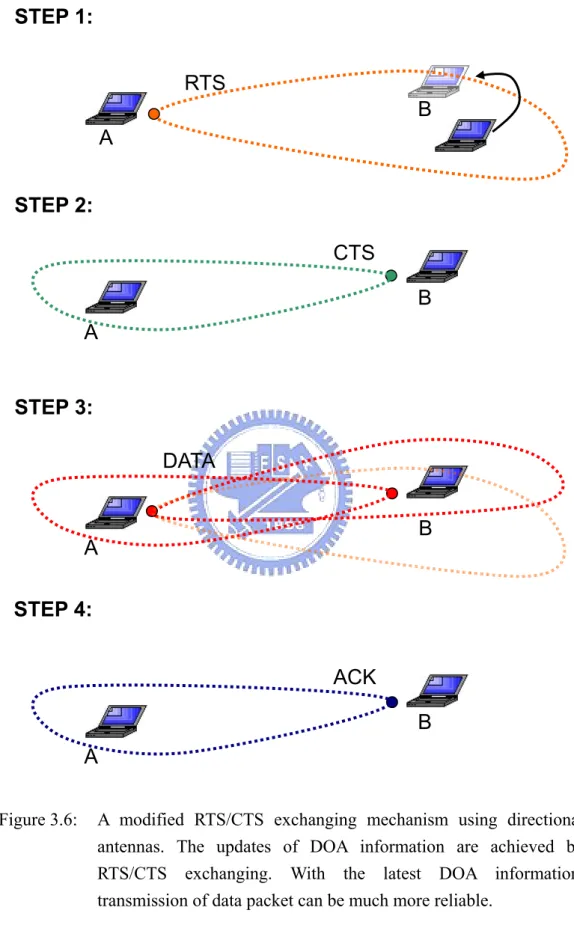
The central element is connected to the main RF radiator. Each passive parasitical element is loaded with a variable reactor. ...55 Figure 3.6: A modified RTS/CTS exchanging mechanism using directional
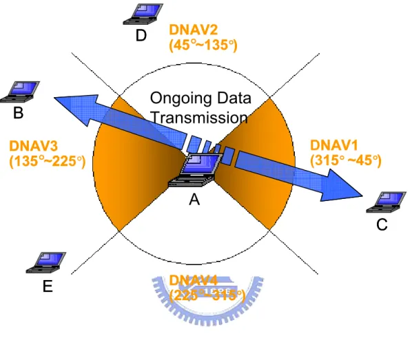
antennas. The updates of DOA information are achieved by RTS/CTS exchanging. With the latest DOA information, transmission of data packet can be much more reliable...56 Figure 3.7 Spatial reuse can be achieved by the adoption of DNAV. Two DNAVs, DNAV1 and DNAV3, reserve the wireless medium for nodes B and C.
The blank area represents available directions for node A’s transmission ...57 Figure 3.8 Flowchart of operation of the cross-layer M-null directional antennas
system ...58 Figure 3.9 An example of transmission using the 4-null directional antennas.
Node A equipped with the 4-null directional antennas has packets to transmit to node B. Node A forms a main beam towards B, and four null angles towards nodes C, D, E, and F. ...59 Figure 3.10 The 4-node inverted T topology ...59 Figure 3.11 Nulling operation under 4-Node inverted T topology: (a) Throughput performance versus data generation rate (b) Packet delivery ratio versus data generation rate...60 Figure 3.12 The 4-node rhombus topology...61 Figure 3.13 Nulling operation under the 4-Node rhombus topology: (a) Throughput performance versus data generation rate (b) Packet delivery ratio versus data generation rate...62 Figure 3.14 Nulling operation under the random topology: (a) Throughput
performance versus traffic load (b) Packet delivery ratio versus traffic load (c) Average delay of packet transmission versus traffic load...64
Figure 3.15 Effect of the number of beamforming nulls: the throughput performance simulations which discuss on the cases in which nodes are equipped directional antennas with zero, two, four, six, and eight beamforming nulls ...65 Figure 3.16 Effect of the beamforming null angle error: throughput performance versus angle error...66
Figure 4.1 An example of the benefit of the power control strategy: (a) The initial state of nodes A, B, C, and D is idle. (b) Node A transmits to node B. (c) Node D transmits to node C. (d) Nodes A and D attack and block each other. (e) Through power control, two transmissions can survive at the same time ...78 Figure 4.2 Flowchart of operation of the cross-layer power control protocol ...79 Figure 4.3 The 4-node linear topology: Node A transmits to node B and node C transmits to node D ...79 Figure 4.4 Performances of the proposed power control scheme under the 4-Node linear topology: (a) Throughput performance versus data generation rate (b) Packet delivery ratio versus data generation rate...80 Figure 4.5 Performances of the power control under 4-Node linear topology: (a) Throughput performance versus traffic load (b) Packet delivery ratio versus traffic load (c) Average delay of packet transmission versus traffic load...82
Figure 5.1 Diagram of the cross layer architecture illustrating how the physical, MAC, and routing layers pass the cross layer parameters, DOAs and Pro, and the corresponding utilization of these parameters...79
List of Tables
Table 3.1 The routing table of DSDV protocol. ...67 Table 3.2 The update packet of DSDV protocol...67 Table 3.3 The neighborhood table of modified DSDV protocol. ...67 Table 3.4 Example of routing table update. With the same sequence number, a route with a smaller metric is preferred. ...68
Acronym Glossary
ABR associativity based routing ACK acknowledgment
AODV ad hoc on-demand distance vector CGSR clusterhead gateway switching routing CSMA carrier sense multiple access
CTS clear to send
DACK directional acknowledgment DBF distributed bellman-ford
DCF distributed coordination function DCTS directional clear to send
DIFS distributed inter frame space DMAC directional medium access control
DMAP directional medium access protocol with power control DNAV directional network allocation vector
DOA direction of arrival DRTS directional request to send
DSDV destination sequence distance vector DSR dynamic source routing
DST dynamic source tracing
DVCS directional virtual carrier sensing
ESPAR electronically steerable passive array radiator FSR fisheye state routing
GPS global positioning system GSR global state routing MAC medium access control
MACA multiple-access with collision avoidance MCMV multiply constrained minimum variance NAV network allocation vector
PCF point coordination function PHY physical
RTS request to send
SSA signal stability-based adaptive
TORA temporally ordered routing algorithm WRP wireless routing protocol
Chapter 1
Introduction
There has been a growing interest in wireless mobile ad hoc networks in recent years. A wireless ad hoc network is a collection of wireless mobile nodes that are dynamically and arbitrarily located in a certain area, and is very distinctive from cellular-based networks mainly because of their lack of centralized control. Moreover, a wireless ad hoc network may consist of many partially overlapping radio coverage areas where a single transmission channel is shared by all of its nodes. In this case, nodes interfere with each other, and without an effective medium access control (MAC) protocol, packet collisions occur frequently. However, the medium reservation policy in recently proposed MAC protocols that aims to solve the collision problem limits network capacity greatly [1].
Directional antennas can provide a higher gain and reduce interference by focusing energy towards an intended direction. Spatial reuse of wireless medium can thus be achieved, and network capacity is increased accordingly. However, the problem of utilizing directional antennas to improve the performance of ad hoc networks is non-trivial. Current directional MAC (DMAC) protocols modified from IEEE 802.11 standard [2], such as [3]-[10], do not benefit by using directional antennas, because these protocols induce new types of hidden terminal [3] and
blocking problems, which result in collisions and inhibiting transmission respectively. Directional antennas, due to its greater transmission range, may potentially interfere with communications taking place far away. It is clear that the problems must be addressed to exploit the benefits of directional antennas.
Another important issue in wireless ad hoc networks is power awareness. The high directional antenna gain will be paramount importance to interfere with communications occurring far away. Power control is a critical factor to limit multiuser interference and increase the number of simultaneous data transmissions. In addition, power is a precious resource in wireless networks. It is a marvelous advantage of reducing power consumption, since the power energy is precious for all ad hoc nodes which are mobile terminals of limited size. Many different power control protocols in wireless ad hoc networks are proposed [11][12][13].
In this thesis, we propose an integrated design of physical, MAC, and routing protocols with the use of directional antennas. We assume that each node has an electrically steerable directional antenna system. With DOA information available, RTS/CTS packets can be transmitted directionally. Upon receiving these control packets, the corresponding direction and duration of the incoming data transmission can be recorded. Therefore, only those nodes located within the direction of transmission are blocked, and these nodes are not blocked in all directions. Spatial reuse can thus be achieved, and the throughput performance is improved significantly. Furthermore, to address problems with DMAC protocols, we propose an M-null directional antennas model which can form M beamforming nulls to eliminate neighbor interference from any other directions except transmission direction. The DOA information helps a node to identify the relative directions of its neighbors; therefore, we can set M null angles in neighbor nodes’ directions. Moreover, our MAC protocol which uses power control on control packets can not only provide an
excellent throughput but also reduce the power consumption. The experimental results show that compared with omni-directional and basic directional approach, the proposed system architecture improves network performance significantly.
This thesis is organized as follows. In Chapter 2, we address issues of medium access control in wireless ad hoc networks. A congestion problem under heavy traffic loading is also discussed. In Chapter 3, we give a detailed description of the proposed system architecture including physical, MAC, and routing layer. We will propose the power control strategy in Chapter 4. Afterwards, computer simulations are presented in the later part of Chapters 3 and 4. Finally, we conclude this thesis and propose some potential future works in Chapter 5.
Chapter 2
Issues in Wireless Ad Hoc Networks
One of the most important key points of wireless ad hoc networks is medium access control (MAC) mechanism. Though there have been lots of MAC protocols proposed and designed for wireless ad hoc networks, the IEEE 802.11 MAC protocol [2] is widely used as the standard of wireless local area networks. However, this protocol does not function well in multihop ad hoc environments. In Section 2.1, we will discuss some limitations induced from the IEEE 802.11 MAC protocol.
To deal with congestion problems in IEEE 802.11 MAC protocol, many research results on directional antenna MAC protocol are proposed. Nevertheless, the existing directional antenna MAC will lead to new MAC problems, which is introduced in Section 2.2.
2.1 Medium Reservation
In a wireless ad hoc network, a single transmission channel is shared by all of the stations. Therefore the network contains many partially overlapping radio coverage areas where stations interfere with each other. A collision occurs when the receiving end hears two or more signals at the same time, which is mainly induced from interference. Obviously, collisions can result in poor network performance. In
order to meet the network performance requirements, MAC protocols with collision avoidance must be well designed.
Due to lack of fixed infrastructure, the interoperability between stations in an ad hoc network becomes much harder. Most proposed MAC protocols are based on the carrier sense multiple access (CSMA) mechanism. The basic idea of CSMA is to reserve the radio channel for the source of a certain on-going transmission by carrier sensing. Any station wishing to transmit must sense the medium first. If some other nodes are already transmitting, the node sets a random timer and then waits for this period of time to try again. On the other hand, if the medium is currently idle, the node begins its transmission. However, the simple CSMA mechanism is susceptible to the hidden node problem, especially in wireless ad hoc networks. We begin our discussion by giving a specific description of hidden node problem.
2.1.1 Hidden Node Problem
In a wireless ad hoc network, a node can communicate with every other node in a certain range directly or use other nodes as relays. Due to lack of fixed infrastructure, it is hard for a node to be aware of other on-going transmissions. Hidden nodes are those out of range of other nodes or a collection of nodes. Thus if some neighbor nodes are already transmitting, a hidden node could send out a signal unintentionally at the same time. The signal from the hidden node collides with the transmitting signal at the receiving end and information will be lost.
As depicted in Figure 2.1, node A is out of the transmission range of node C. If node C is transmitting signal to node B, node A will not know that node B is receiving signal from node C. In the meanwhile, collision could occur at node B if node A decides to send out signal. In this case, node A is known as a hidden node. As
mentioned before, hidden nodes can cause costly packet collisions and significantly reduce network performance. When a collision of data packet occurs, the data packet will be discarded, and the system must waste time on retransmissions. Therefore, many MAC protocols have been proposed to eliminate the hidden node problem.
2.1.2 RTS/CTS Exchanging Mechanism
In order to solve the hidden node problem, and thus achieve high throughput, a mechanism known as RTS/CTS exchanging is widely used. The RTS/CTS exchanging mechanism was initially proposed in a protocol called multiple-access with collision avoidance (MACA) [14]. A node wishing to send a data packet must firstly broadcast a request-to-send (RTS) control packet which contains the length of the data packet that will be sent. After receiving the RTS packet, the receiver responses by sending out a clear-to-send (CTS) control packet which also contains the length of the upcoming data packet. According to the data length information, any node hearing either RTS or CTS packet must set a timer to record the end of upcoming data transmission. Thus all the neighbors of the transmitting end and the receiving end will be informed about the data transmission by RTS and CTS control packets respectively. These nodes remain silent until the data transmission is completed, and therefore collisions are avoided. As shown in Figure 2.2, node B wants to communicate with node C. Node B first sends out an RTS control packet and waits for response from node C. At the same time, node A is blocked by this RTS packet and remains silent until the end of the following data transmission. Upon receiving the RTS packet, node C sends out a CTS packet to show that it is ready for receiving data from node B. Node D also receives this CTS packet and will not send out any signal. After exchanging RTS/CTS packets, node B can start transmit data
packet to node C without been interfered. This example clearly shows how the hidden node problem is eliminated by RTS/CTS exchanging mechanism, and thus collisions are avoided. Via this control packet exchanging process, all the hidden nodes won’t transmit during the period of data transmission, and the effect of hidden node problem is eliminated.
However, in an ad hoc network with heavy load, there could be lots of nodes wishing to transmit data packets at the same time. This could result in the flood of RTS packets, and the flooded control packets could prohibit a large number of nodes from transmitting any packet. Consequently, the throughput of the network goes to zero as the load increases. Before giving a further description of this problem, the most widely used MAC protocol, IEEE 802.11 MAC protocol, will be introduced in the following section.
2.1.3 IEEE 802.11 DCF protocol
The IEEE 802.11 protocol covers the MAC and physical (PHY) layer. The MAC layer defines two different access methods, the distributed coordination function (DCF) and point coordination function (PCF). Since the PCF cannot be used in ad hoc networks, the following discussion will focus on the DCF protocol.
IEEE 802.11 DCF protocol is basically a carrier sense multiple access with collision avoidance mechanism which is implemented by RTS/CTS exchanging. All other nodes receiving either the RTS or CTS packet set their virtual carrier sensing indicator, called a network allocation vector (NAV). The NAV is a counter counts down to zero at a constant rate, which is updated according to the duration field in the control packet. Before the NAV counts down to zero, the virtual carrier is sensed
busy. Thus the area covered by the transmission range of the sender and the receiver is reserved for data transmission. In addition to the RTS/CTS packets, IEEE 802.11 DCF protocol requires an acknowledgment (ACK) packet transmitted by the receiver after the successful reception of data packet. The sender ascertains the success of data transmission by receiving the ACK packet. If no ACK packet is received, data retransmission can be initiated immediately.
IEEE 802.11 DCF protocol also employs a congestion control mechanism based on random backoff. When a node has data to transmit, it detects the wireless medium first. If the medium has been idle for more than a time interval called distributed inter frame space (DIFS), this node can transmit the data packet immediately. Otherwise, it waits until the medium becomes idle, and then defers for another DIFS interval. If the medium remains idle after this DIFS interval, the random backoff mechanism is started. Without the backoff mechanism, collisions may occur just at the moment because there may be more than one node waiting for the medium to become free. The node sets a backoff time that is randomly selected from interval [0 CW], where CW is the contention window value maintained in every node. At the first transmission attempt, CW is set as CWmin, and it is doubled at each retransmission
up to CWmax. Once CW is set to CWmax, it remains at the value of CWmax until it is
reset. The backoff timer counts down as the channel is sensed idle, pauses during data transmission, and reactivates when the medium is sensed idle again. When the backoff timer expires for more than a DIFS and the medium is still idle, the node starts transmission. If data is transmitted successfully, or maximum retry limit is reached, CW will be reset to CWmin. Figure 2.3 shows a complete packet exchanging
timing diagram of an IEEE 802.11-based wireless ad hoc network, where SIFS stands for short inter frame space. SIFS is the smallest time interval defined in the IEEE 802.11 MAC protocol. After a SIFS, only acknowledgements, CTS or data
frames may be sent. At the end of a defer process, every node starts a backoff process to avoid collision at this very moment.
As mentioned before, the RTS/CTS exchanging mechanism could result in poor throughput performance, especially in heavy load networks. The following section will give a thorough explanation of this RTS/CTS-induced congestion problem.
2.1.4 Blocking Problem
In the RTS/CTS exchanging mechanism, any node receiving either an RTS or CTS packet will be blocked for a certain period of time to ensure not to interfere with on-going transmissions. Since nodes in an ad hoc network share a single transmission channel, only one node is allowed to transmit at any time within the range of a receiver, and all the other nodes may be blocked. As for the neighbors of a blocked node, these nodes will not be aware of the fact that this node is blocked. Therefore, communication with the blocked node may still be initiated by its neighbors. In this situation, the sender sends out an RTS packet and waits for response. However, the blocked destination will not respond to this RTS packet. Since the sender does not get any response to its RTS packet, it enters into an exponential backoff mode. Furthermore, this RTS packet forces every other node that receives it to inhibit any transmission even though the blocked destination does not respond. Without a CTS response, data transmission will not be ignited. It’s a waste of medium that stations been inhibited from transmitting while no data transmission takes place actually.
Figure 2.4 explains the problem. In this figure, data packets are transmitting between node A and node B, and node C is blocked by the RTS/CTS packets from nodes A and B. In the period that node C is blocked, node D sends out an RTS packet
to node C and won’t get CTS response back. Meanwhile, node E is blocked due to the RTS packet from node D. However, node E is unnecessarily blocked because it is out of the transmission range of nodes A and B. This blocking situation could propagate through the network and result in a severe problem that the throughput of the network goes to zero. If node F sends an RTS packet to node E while node E is blocked, not only node F enters into backoff mode, but also node G is unnecessarily blocked due to the RTS packet from node F. Only nodes in the gray area are required to be blocked. However, node E and node G are blocked as well. As for node D and node F, they are forced to enter backoff mode. Neither nodes in backoff mode nor nodes been blocked can transmit data, which wastes lots of radio resource. This is how blocking problem propagates and it may affect network performance severely as the load increases. From this example, we clearly show how the RTS/CTS-induced blocking problem affects the network performance. The most significant drawback is the poor throughput performance. As the load of network increases, more RTS packets are sent out, and thus more nodes are blocked. Since no node transmits data, the throughput is drastically reduced.
2.2 Directional Antenna for Wireless Ad Hoc
Networks
Directional antennas offer tremendous potential for improving the performance of wireless communication systems. In this section, we introduce recent topics about directional antenna for wireless ad hoc network.
2.2.1 Classification of MAC Protocols for Directional
Antenna Models
Directional antenna models using for wireless ad hoc networks can be classified into two groups: steered beam and switched beam antenna systems and there have been several MAC protocols for different directional antenna models proposed for wireless ad hoc networks. A steered beam system can steer the main lobe of the beam, which is sectorized in simulation, in the direction of the desired user. Each node is equipped with M antennas whose orientations can be maintained at any time, regardless of the node’s movement. In this model, it is assumed that nodes have directional reception capability, i.e., they can activate the antenna pointing to the direction of the desired destination while deactivating antennas in all other directions. Thus, the receiving node is not influenced by simultaneous transmissions from other nodes as long as it is not received at the antenna low beam when the receiver is currently listening to. Many recent researches adopt this antenna model [3]-[5].
The first MAC protocol using steered beam system uses omnidirectional RTS as well as CTS packets [5]. DATA and ACK packets are transmitted and received in the sector antennas facing the receiver and transmitter, respectively. The second MAC
protocol sends a directional RTS and an omni directional CTS [6]. These MAC protocols employ at least one omnidirectional transmission of a control packet that leads to several inefficiencies. First, they do not fully exploit the potential benefits of directional antennas because omnidirectional RTS/CTS block neighbor nodes in all directions, and spatial reuse cannot be obtained. Second, omnidirectional transmission of a control packet causes to limit the coverage area. The presence of omnidirectional transmissions of either RTS or CTS limits the range of directional transmissions, which is now defined by the smaller coverage range between any of these packets. They do not exploit the increased coverage range provided by directional transmissions. In other words, given a particular transmit energy, an array of M antenna beams provides an increased antenna gain in comparison with the omni mode of the order of M [5][6][10]. This gain is doubled if there is directivity in both transmission and reception. Thus, a directional communication between two stations may significantly increase the distance between them as compared to the equivalent omni communication, a benefit that has not been explored by the above schemes.
In [3], the directional MAC (DMAC) protocol is proposed that RTS/CTS and DATA packets transmit directionally. Since DMAC has more spatial reuse, DMAC can have better performance, but it will increase instances of hidden terminal problem.
Another directional antenna model is a switched beam system which consists of a set of predefined beams, of which the one that best receives the signal from a particular desired user is selected [4]. As we can see in Figure 2.5, the area around the node is covered by M beams. The beams are numbered from 1 to M starting at the three o’clock position and running counter clockwise. The node can transmit its signal to anyone of the M beams, increasing the coverage range of the transmission towards a specific direction. In idle mode the node hears omnidirectional. In the
reception of a signal the node uses selection diversity, which means that it uses the signal from the antenna that is receiving the maximum power of the desired signal. With this mechanism the receiver can extend the communication area.
A scheme of circular directional transmission of RTS is carried out by the transmitter which ensures that the RTS packet will eventually reach the intended destination [4]. The destination then sends back a single directional CTS packet towards the source. This scheme can be referred as Circular RTS MAC (CRM).A more serious problem with CRM is in the design of its RTS/CTS handshake. For example, if the destination node does not reply back with a CTS (due to a collision), nodes in the neighborhood of the transmitter which correctly receive the circular RTS will not be able to initiate any transmission as their Directional Network Allocation Vector (DNAV) is set. Clearly, this degrades the network capacity. Another limitation in CRM is transmission of circular directional RTS through “empty” sectors which do not have any neighbor nodes. In [15], Directional Antenna Medium Access (DAMA) protocol is proposed and performs more effectively than CRM. However, DAMA and CRM is inferior to IEEE 802.11 in few antenna beams in grid topology, because they cannot benefit much from spatial reuse when the load is low as it spends a considerable amount of time performing the circular transmissions of RTS.
In these MAC protocols for directional antenna models aforementioned, the directional antenna models use simple but impractical models in their simulation. In steered beam and switched beam system, the main lobe beam is simulated as sector beam which antenna pattern is flat-topped within the width of the main lobe beam. They approximate the radiation pattern of the low beams into a sphere with the node at its center and the gain of the low beams is assumed to be very low. There is not an antenna array can formulate an antenna pattern which has a flat-topped main lobe beam and low beams with very low gain. In many adaptive beamforming arrays, the
gain of low beams is approximately one-tenth of gain of the main lobe. We will propose a practical directional antenna model and show that the influence of the gain of low beams is very greatly in wireless ad hoc networks.
2.2.2 Problems of Existing Directional Medium Access
Control (DMAC) Protocols
In this section, we discuss some channel access problems of existing directional MAC protocols in wireless ad hoc networks. These problems can be classified in hidden terminal and blocking problems.
A. Hidden Terminal Problems
In section 2.1.1, we have discussed the well-known hidden terminal problem in multi hop wireless networks can be resolved by the exchange of RTS/CTS control packets. However, the RTS/CTS exchange assumes that these packets are transmitted omnidirectionally. If directional antenna adopts DMAC protocol, directional transmission of RTS/CTS introduces new kinds of hidden terminal problems, which are discussed below.
(1) Hidden terminal due to asymmetric gains in omnidirectional and directional modes:
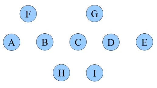
Assume that all nodes in this figure are currently idle in Figure 2.7. Nodes have an omnidirectional gain of Go. The protocols in [9][16] use equal directional gain of
Gd for directional RTS/CTS (DRTS/DCTS) and data packets. Gd is greater than Go. In Figure 2.7, assume that node C sends a DRTS to node D and node D replies with a
DCTS. Nodes C and D form their transmission and reception beams in each other’s direction, and node C starts transmitting DATA to node D. At the same time, node A is in the idle mode listening omnidirectionally and is distant from node D, so it does not hear the DCTS and cannot sense this transmission. While this transmission is in progress, assume that node A has a data packet to send to node B, and thus sends a DRTS to node B with a directional gain of Gd. Since node A and node D now also form beams in each other’s direction, node D possibly receives DRTS/DATA from node C and A simultaneously, and then a collision is occurred. This problem is identified in their protocol but is not addressed [3]. The DMAC protocols proposed in [9][16] do not also resolve this problem.
(2) Hidden terminal due to unheard RTS/CTS:
Suppose that in Figure 2.7, node B is transmitting to node A. While this transmission is in progress, node C exchanges RTS/CTS packets with node D and is sending data to node D. Since node B forms a beam in the direction of node A, it cannot receive the DCTS from node D. In this scenario, node B is unaware of the ongoing transmission in its neighborhood, although B is within the transmission range of node D. Assume after node B finishes transmitting to node A, and now intends to transmit packets to node D. Consequently, node B sends a DRTS packet to node D and a collision is occurred at node D. The MAC protocols proposed in [3][9][16 ] suffer from this problem.
(3) Hidden terminal due to low beams:
Low beams represent the power radiated/received in directions other than the intended direction. Consider Figure 2.7 again, if node A intends to send data to node B, it first sends a DRTS to node B. When B replies with a DCTS, node A starts sending the data packet. Node H does not hear the DCTS since it is not located in the
direction of the main lobe of node B. Furthermore, assume that the gain of the low beams of node B is comparatively small, and node H is listening omnidirectionally. Meanwhile, node H has data for node B, and thus, points its main lobe towards node B. Even though node B has only a low beam in the direction of node H, the high antenna gain of the main lobe of node H could result in a collision at node B. However, in this case, the interferer is sending the signal towards the low beams of the receiver. This problem remains unresolved in the protocols in [3][9][16].
(4) Hidden terminal due to vulnerable transmitter:
Assume that node H sends a DRTS to node G in Figure 2.7, and node G replies with a DCTS. After receiving the DCTS, node H commences data transmission. This DRTS/DCTS exchange is heard by node C, which sets its DNAV accordingly. Meanwhile, node C intends to send a data packet to node B. Node C’s DNAV in the direction of node B is not set, and thus it sends a DRTS to node B and waits for a DCTS. However, node H points its main beam towards node C, and node C has finite low beam gain in node H’s direction. Therefore, the received power from node H at node C may be significant. In the meanwhile, if node B replies with a DCTS, this causes a collision at the node C. Thus, nodes in the vicinity of a transmitter may not be able to initiate data transmission even in the free DNAV directions while a neighbor transmitter is sending data. A similar problem can be occurred when a transmitter is expecting an acknowledgement (ACK) following a data packet transmission.
B. Blocking problems
(1) Blocking problem due to low beams:
In Figure 2.7, assume that node G and I are close to node C. Node C has packets to send to D, so it sends a DRTS to D first. Although the gain of the low beams is one-tenth of gain of the main beam approximately, nodes G and I which are in omnidirectional mode can still sense the DRTS from node C. Consequently, nodes G and I are blocked, so they cannot communicate with each other. However, node G cannot transmit to nodes C and D in this scenario, which implies that collisions are not occurred. This apparently implies a potential tradeoff between spatial reuse and collisions when using directional antennas.
(2) Blocking problem due to high gain:
Suppose that in Figure 2.7, node A has packets to send to node B. Since node A sends DRTS to node B with high directional gain of Gd, node D can receive the DRTS packet from node A, even D locating out of the omnidirectional transmission range of node A. Then, node D is blocked in the direction of node A. In the period that node D is blocked, node C sends out an DRTS packet to node D and will not get DCTS response back. Meanwhile, node E is blocked due to the DRTS packet from node C. However, node D will not be blocked when it operates in IEEE 802.11 omnidirectional mode. Node E is also unnecessarily blocked because it is out of the transmission range of nodes A and B. This blocking situation could propagate through the linear topology, which nodes are arranged into a line, and result in a severe problem that the throughput of the network reduces drastically. As for node C, it is forced to enter backoff mode. Neither nodes in backoff mode nor nodes been blocked can transmit data, which wastes lots of radio resource. As the load of linear topology increases, more RTS packets are sent out, and more nodes are blocked.
Therefore, no node transmits packets, and then the throughput decreases greatly.
2.3 Summary
In a wireless ad hoc network, a single transmission channel is shared by all of the stations. The main function of MAC layer is to manage the use of the shared medium. IEEE 802.11 MAC protocol is the most widely used protocol in the current implementation of wireless ad hoc network. This protocol is basically based on the CSMA protocol. In order to solve the hidden node problem, IEEE 802.11 MAC protocol exploits the RTS/CTS exchanging mechanism. The RTS/CTS exchanging mechanism is widely used in wireless ad hoc networks to avoid collisions caused by hidden nodes. Any node that receives an RTS or CTS packet inhibits itself from transmitting. Therefore, data transmission can be completed without the occurrence of collisions.
However, the RTS/CTS exchanging mechanism could lead to blocking problem where a node could be blocked even though there is no nearby node transmitting. Moreover, the blocking problem may propagate through the network, and the throughput goes down as the load increases. From a network point of view, the blocking problem reveals the tricky point of MAC functionality. On the one hand, MAC protocols must manage the shared medium to ensure successful data transmission, but on the other hand the medium reservation policy induces congestion in the network, like the blocking problem. Directional antennas have been suggested to be used in wireless ad hoc networks to reduce interference outside the intended direction, which increases spatial reuse of the transmission medium. However, from the previous sections we know that the throughput reduction results from the limitation of medium reservation. Features of directional antenna with
DMAC protocol can alleviate the network congestion.
We have shown that previous research results on DMAC for wireless ad hoc network using directional antenna introduce new types of problems (such as hidden terminal problems, and blocking problem), and the directional antenna models used at network simulation engine (ex. NS2) are too simple to be practical. In the following chapters, we will present our system architecture and computer simulations to show that the proposed scheme overcomes the shortcomings in DMAC and achieves better throughput than IEEE 802.11 and basic directional antenna model with few antenna elements in wireless ad hoc networks.
A
C
B
Figure 2.1: Hidden node problem: Node C is sending data packet to node B. Node A is out of radio range of node C, and thus is a hidden node. Collision occurs at node B when node A initiates transmission.
Figure 2.2: Node B and node C do the RTS/CTS exchanging before data transmission. Node A and node D are blocked by the RTS packet and the CTS packet, respectively.
B
C
D
RTS
CTS
RTS CTS CTS RTS DATA DATA ACK ACK NAV (RTS) NAV (CTS) SIFS SIFS SIFS DIFS DIFS
DEFER ACCESS BACKOFF
Source
Destination
Others
A
B
C
BlockedE
BlockedG
BlockedF
RTS RTSD
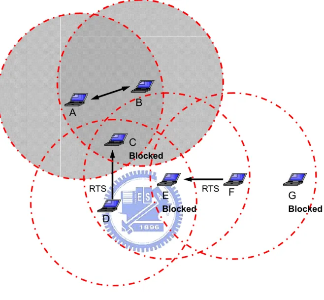
Figure 2.4: Blocking problem: Node A and node B are transmitting data packets. Only nodes in the gray area are required to be blocked. Node E and node G are unnecessarily blocked. This figure also shows how blocking problem propagates.
Omni coverage area
Directional coverage area
Figure 2.5: The sectorized antennas model [4]
A
B
C
D
H
E
I
G
F
Figure 2.7: A topology used to demonstrate the hidden terminal and blocking problems in existing MAC protocols
Chapter 3
Performance Enhancement via
Directional antennas
Directional antennas offer tremendous potential for improving the performance of wireless communication systems. Continuing reductions in the cost and size of antenna arrays make it feasible for wireless mobile ad hoc networks. By using directional antennas, radio interference can be reduced effectively, thereby improving the utilization of wireless medium. With directional antennas, simultaneous data transmissions of two or more pairs of nodes located in each other's vicinity may be allowed. However, we have shown that the throughput reduction results from the new types of hidden terminal and blocking problems in existing DMAC protocols. Therefore the merits of directional antennas may not be fully exploited without the modification. In this chapter, we present an integrated physical, MAC, and routing layers design of new directional antennas model, M-null directional antennas model, to utilize the advantages of directional antennas and address the problems in existing DMAC protocols.
3.1 System Architecture
From the previous chapter, we know that the throughput of a wireless ad hoc network could go to zero as the traffic load increases. The goal is to utilize the features of directional antennas and diminish this situation. Figure 3.1 illustrates a network situation where network capacity is improved by using directional antennas. Node C is allowed to initiate data transmission to node D while nodes A and B are transmitting. Moreover, although node G is located in the middle of nodes E and F, data transmission between nodes G and J will not interfere with nodes E and F. However, transmission between nodes G and H is not allowed, because node G is blocked in the direction of data transmission between nodes E and F. In normal situations where nodes are equipped with omni-directional antennas, most of these nodes are blocked. Data transmission between these nodes must take turns by contention. At most two sessions are allowed to be held simultaneously.
In the following discussion, the main idea is to share the knowledge of the wireless medium at the physical layer with higher layers. In standard wireless ad hoc networks, omni-directional antennas are utilized at the physical layer, which provides only information about received power. More useful information, direction of arrival (DOA) can be gained via the use of directional antennas. The DOA information will be shared with higher layers. From the previous chapter, we know that the fundamental resolution to blocking problem is to modify the MAC protocol. The MAC layer protocol should not block all the other neighbors in all directions. Since directional antennas can focus energy in an intended direction, spatial reuse can be achieved. With DOA information available, nodes can be aware of directions of on-going transmissions. As a result, data transmission may be initiated on the premise that no on-going transmissions will be interfered. In order to fully exploit the
advantages of directional antennas, the DOA information can be further utilized at the network layer.
3.2 Physical Layer: Directional antennas
Wireless ad hoc networks are conventionally equipped with omni-directional antennas. However, the technology of directional antennas for wireless mobile communication has received enormous interest in recent years. In this section, we present the implementation of directional antennas at the physical layer.
3.2.1 Features of Directional antennas
Directional antennas have the ability to concentrate the radiation towards the intended direction of transmission or reception. Individual elements on the directional antennas transmit signals omni-directionally, and these signals interfere with each other constructively or destructively. As a result, signal strength increases in one or more directions and eliminates in the others. Consequently, the amount of radiated power to the destined node is reduced, which can largely improve the energy efficiency. However, in the case of omnidirectional antennas, the transmitted power radiates equally well in all directions and only a small percentage of power reaches the destined node. Moreover, because directional antennas have a lower gain outside the intended direction, interference can be minimized. Figure 3.2 shows an example of beam pattern steered by an 8-element circular antenna array [17]. It has a main lobe with about 60° width and gain of 8. The radiated power is concentrated in the range from -30° to 30°, and is suppressed outside the range. In addition to the main
lobe, there are also several side lobes which represent the loss of energy. With more elements on the directional antennas, the increased signal strength in the intended direction can be larger, and the control over beamwidth and direction can be more effectively. The communication area can be extended via the use of directional antennas, and the communication link can benefit more by beamforming at both transmitter and receiver.
3.2.2 Multiply Constrained Minimum Variance (MCMV)
Beamforming
Before introducing the proposed M-null directional antennas model, we introduce Multiply Constrained Minimum Variance (MCMV) beamforming [18], which the proposed M-null directional antennas model is based on in this section. The array data model:
1 ( ) D i i i= s θ =
∑
+ = x a n As+ n (D×1) (3.1)where s = [s1, s2, …, sD]T is a transmitted symbol vector, A = [a(θ1), a(θ2),…, a(θD)]:
D×D, a(θi) is an array steering vector: D×1, θi is a DOA of the ith path, and n(k) is a noise vector.
The design of an MCMV beamforming involves minimizing the output power subject to the constraints that the desired signal receives a unit gain and the coherent interferers get rejected. Assume that we have information about desired source DOA
θ1 as well as interference DOAs θi, i = 2,…, D. We want to pass desired source distortionlessly while rejecting sources 2 ~ D in a “hard” manner that adds auxiliary constraints to put nulls at θi, i = 2,…, D to suppress noise and undetected interference
with minimum power criterion. Determine the optimum weight vector w by solving the following optimization problem:
2 1 min {| ( ) | } subject to: ( ) 1 ( ) 0 2,..., H H MC MC xx H MC H MC i E k i D θ θ ⎧ = ⎪ ⎪ = ⎨ ⎪ = = ⎪ ⎩ w w x w R w w a w a MC ]}) 0 − = 1 − e 1 =
where Rxx = E{x(k)xH(k)}: D×D is the autocorrelation of x(k). Solution by Lagrange Multipliers:
1 ( { ( ) [1 ( ) [1 ] 2,..., MC D H H MC xx MC i MC i i H MC i i i i D λ θ δ θ δ = ⎧ ∇ − − ⎪ ⎨ ⎪ = − = ⎩
∑
w w R w w a w a s.t. 1 1 ( ) D xx MC i i i H T MC λ θ = ⎧ = = ⎪ ⎨ ⎪ = ⎩∑
R w a Aλ w A e where λ= [λ1,..., λD]T: D×1, and e1 = [1, 0,…, 0]T: D×1With some manipulation:
1 1 1 ( H ) MC = −xx −xx w R A A R A (D×1) (3.2) Check: 1 1 1 1( ) H T H H H H T MC xx xx − − − = w A e A R A A R A e (3.3)
MCMV beamforming approach can be applied to an array of arbitrary geometry for suppressing coherent and in coherent interference. The optimal weights are generated to form beamfroming nulls in the coherent interferers’ directions of ±30°, ±60°, ±100°, ±160° in Figure 3.3.
If there is an angle error in estimation, the beamforming nulls cannot eliminate coherent interference completely. There are two methods to counteract the angle error. Firstly, using high-order null constraint is very effective in counteracting the angle error in estimation. Secondly, setting two beamforming null constraints near the direction of main interference can have a wide angle range of beamforming null to tolerate large angle error. For example, as shown in Figure 3.4, we set two beamforming null constraints in 59° and 61°, there is a wider angle range of the beamforming null in 60°.
3.2.3 M-Null Directional antennas Model
Most studies on wireless ad hoc networks with directional antennas have assumed the use of a small, low-cost adaptive antenna which is known as electronically steerable passive array radiator (ESPAR) antenna [19]. As shown in Figure 3.5, the (M+1)-element ESPAR antenna consists of one center element connected to the main radiator and M surrounded passive parasitical elements in a circle. The main radiator exhibits an omni-directional radiation pattern. Each passive parasitical element is loaded with a variable reactor. The antenna pattern is formed according to the bias voltage on the reactors, and thus the reactance values. The ESPAR antenna is capable of forming either omni-pattern or directional pattern. For omni-pattern forming, the bias voltage on each reactor is set equally on condition that the received power is maximized [20]. For directional pattern forming, an optimized set of bias voltage on reactors is obtained such that the received signal power is maximized in the direction of the source.
According to MCMV beamforming in Section 3.2.2, we can use (M+1)-element antennas to build an M-null directional antennas model, which has one main beam,
M-1 side lobes, and M beamforming nulls. For ad hoc networks, a simple circular antenna array is capable of steering a beam through all 360°. M-null directional antennas can concentrate the radiation towards the intended direction of transmission or reception and null interference in specific direction, so it can completely utilize the potential of spatial reuse, and alleviate the hidden terminal problems and blocking problems. In latter simulations, we will show that M-null directional antennas model achieves outstanding performance over the basic directional antennas communications and IEEE 802.11 omnidirectional antennas.
In the following discussion, the antenna system on each node is assumed to be capable of operating in two modes; omni-mode and directional mode. Both the omni and the directional modes can be used to transmit or receive signals. In omni-mode, a node is capable of receiving or transmitting in all directions with a constant gain of Go. A node stays in omni-mode while idle. In directional mode, a node can point its antenna beam towards an intended direction with a gain of Gd which is typically larger than that in omni-mode. Consequently, a node in directional mode has a greater transmission range than in omni-mode. The direction in which the main lobe should be steered for a given transmission is specified to the antenna by the upper layer protocol. When a node is in the omni-directional receiving mode, it is susceptible to interference from all directions. Only when the node has formed a beam to a specific direction, it can avoid the interference from other directions.
3.3 MAC Layer: DMAC
Current MAC protocols, such as IEEE 802.11 standard, do not benefit when using directional antennas, because these protocols have been designed for omnidirectional antennas. To best utilize directional antennas, a suitable MAC protocol must be well designed. The use of RTS/CTS exchanging mechanism is optional in the standard, and is assumed to be used in the following sections. The basic idea of directional MAC (DMAC) protocol is to block only those nodes located within the direction of upcoming data transmission. An intuitive way to achieve this goal is to transmit RTS/CTS packets directionally, which can thus largely reduce the number of blocked nodes. Furthermore, those nodes which received RTS/CTS packets are not blocked in all directions. Through the adoption of directional network allocation vector (DNAV) [6], these nodes can initiate data transmissions in some other directions. In the following, a DMAC protocol based on directional virtual carrier sensing (DVCS) [9] will be introduced.
3.3.1 Neighbor Node Location Identification
In order to steer the antenna beam to an accurate direction in its next hop and send out RTS/CTS packets directionally, the sender needs to know the relative locations of its neighbors. Some related works on DMAC protocol assume that the physical location information may be obtained by using the global positioning system (GPS), ultrasound, or multiple orthogonal channels for control packet transmission. However, these additional resource requirements could make the protocol impractical and unrealistic. For nodes equipped with directional antennas,
neighbor node locations can be obtained by direction of arrival estimation techniques. Each node caches estimated DOAs from neighbor nodes when it hears any signal, regardless of whether the signal is sent to the node. In a complex environment where lots of scattering, reflection and diffraction could be induced, the result of DOA estimation may not match the physical relative direction which could be obtained by external devices such as GPS. However, the DOA information based on signal strength evaluation may be much more practical than physical location information. In other words, the DOA is the most effective direction to reach the transmitter with the minimum path loss. The DOA information is updated every time the node receives a new signal from the same neighbor. With DOA information available, RTS/CTS packets can be transmitted in an accurate direction. Therefore, only those nodes located within the direction of upcoming data transmission will be blocked. The DOA caching mechanism is implemented at routing layer and will be introduced in Section 3.4.2.1.
3.3.2 Modification of RTS/CTS Exchanging Mechanism
This DMAC protocol is an enhancement to the IEEE 802.11 MAC protocol. As mentioned before, two modes of antenna operation are available; omni-directional mode and directional mode. A node listens to the channel omni-directionally when idle. In the DMAC scheme, the RTS, CTS, DATA, and ACK packets are sent directionally. Firstly, as in the IEEE 802.11 protocol, the sender sends out an RTS packet prior to data transmission. The RTS packet is sent directionally to the receiver according to the DOA information. When the receiver receives this RTS packet, it not only updates the DOA information, but also adapts its beam pattern to maximize the received power and locks the pattern for the CTS transmission. Once the sender
receives the CTS packet, it updates the DOA information and adapts its beam pattern for the data transmission as well. This beam pattern adaptation process provides a more reliable data transmission. During the data transmission, beam patterns are locked toward each other for both transmission and reception, and are unlocked after the completion of ACK packet transmission. These locked patterns maximize the signal power at the receiver as long as the channel condition remains the same. Since the period from CTS through ACK transmission is for only a short period of time, the channel response may be assumed to be stable.
Figure 3.6 shows the steps of beam locking and unlocking. Assume that node A has data to be sent to node B. At the first step, node A transmits an RTS packet directionally toward node B according to the last updated DOA from node B. Although this RTS packet may not be sent in an accurate direction due to node movements, the direction of the upcoming data transmission can be corrected in the following steps. Upon receiving the RTS packet, node B updates its DOA information and locks its beam pattern to this newly derived direction for CTS packet transmission. At the second step, node B sends out a CTS packet toward node A. Node A updates its DOA information and locks its beam pattern to node B as well. At the third step, node A starts to transmit data packet. These locked beam patterns provide reliable data transmission at both sides. Eventually, data transmission is completed with an ACK packet replied from node B directionally.
3.3.3 Directional Network Allocation Vector (DNAV)
The value of network allocation vector indicates the duration of the ongoing transmission in the vicinity, and the node must reserve the channel for those acting nodes by deferring its own transmission. Directional NAV is an enhancement of NAV,
which reserves the channel only in a certain range of directions. The design of DNAV is to release the medium which is not necessarily reserved, and thus spatial reuse can be achieved. If a node receives an RTS or a CTS packet from its neighbors, a DNAV is set. Each DNAV is tagged with two important values; the direction where the control packet comes from and the duration of the corresponding data transmission. A node cannot transmit any signals whose direction is in the range of unexpired DNAVs. Another important factor is the width of DNAV, which is based on the beamwidth formed by the directional antennas. The DNAV width of a node must be larger than the beamwidth.
Assume that the width of DNAV is 2w degrees and the beamwidth is 2b degrees. For a node transmitting safely, it must refer to its DNAV table and the difference between the transmitting direction and all the DNAVs must exceed (w+b) degrees. In other words, the antenna beam intended to a certain direction must not overlap with any unexpired DNAVs. In the following discussing, we set that the width of DNAV is 45°; the range of DNAV1 is from 315° to 45°; the range of DNAV2 is from
45° to 135°; the range of DNAV3 is from 135° to 225°, and the range of DNAV4 is
from 225° to 315°. Figure 3.7 shows a simple example where spatial reuse is achieved. Node B has data packets to send to node C, and data transmission is initiated after RTS/CTS exchanging. Node A received RTS and CTS packets from nodes B and C, respectively. Two DNAVs with 45° width, DNAV1 and DNAV3, are set upon the
reception of these control packets. The numbers in the parentheses represent the relative angles between node A and these two active nodes. If node A has a packet to be sent to node D or node E, it must refer to its DNAV table to check if there is any transmission ongoing in the corresponding direction. Node A cannot transmit any signal to node E until the expiration of DNAV3 which was set upon the reception of
any DNAV, and can be ignited. As mentioned in Section 3.3.1, the DOA is always the most effective direction towards the transmitter with the minimum path loss. This also implies that transmissions towards the DOA of the transmitter could cause the most interference. Therefore, the most effective way to avoid collisions is to set DNAV according to the DOA even the signal DOA does not match where the transmitter is physically located. The width of the DNAV can also be adjusted for the control of aggressiveness of a transmitter. A DNAV with a narrower width makes more directions available for transmission, and thus makes the transmitter more aggressive.
To best exploit the advantages of directional antennas, the routing protocols should be modified as well. The relative direction information of neighbor nodes can be further utilized. In the following section, we introduce the basic concepts of routing protocols in ad hoc networks, and achieve our goal by modifying a well-known routing protocol, the DSDV routing protocol.
3.4 Routing Layer
A wireless ad hoc network is a collection of mobile nodes that are free to move arbitrarily in a certain area where interconnections between nodes could change continuously. Moreover, in a wireless ad hoc network, a node can communicate with every other node in a certain range directly or use other nodes as relays. Due to lack of infrastructure, nodes themselves function as routers which discover and maintain routes to other nodes in the network. Discovering a route is to form a path from a source node to a destination node by selecting nodes in the network as relays. Maintaining a route is to take actions to reconstruct a broken route when one of the
relays on the route is no longer available. Without an effective construction of routes, packets cannot be delivered reliably from one node to another, especially under a fast changing topology. The design of efficient routing protocols is the important issue in such dynamic wireless networks.
In order to fully exploit the advantages of directional antennas, we want to find a suitable routing protocol. Therefore, our goal is to establish a routing mechanism which can provide the information for physical and MAC layers. Before proceeding with the discussion of the proposed routing protocol, the classification of current routing protocols will be introduced in the following section.
3.4.1 Classification of Current Routing Protocols
There have been several routing protocols proposed for wireless ad hoc networks [21]-[32]. Depending on when the route is computed, these routing protocols may be categorized as: table-driven routing and on-demand routing protocols [33]. Table-driven routing protocols are also called proactive routing or pre-computed routing protocols. As implied by the name, table-driven routing protocols attempt to maintain a table which consists of up-to-date routing information from each node to every other node in the network. In order to maintain a consistent network view, updates of routing information are propagated throughout the network periodically or whenever the link state of the network changes. The advantage of table-driven routing protocols is that a route to the destination is already available when a source wants to send packets to a certain node in the network. However, the propagation of routing information could result in flooding of update packets, which consumes a lot of the wireless network bandwidth. Destination sequence distance vector (DSDV) [21], clusterhead gateway switching routing
(CGSR) [22], wireless routing protocol (WRP) [23], global state routing (GSR) [24], and fisheye state routing (FSR) [25] are examples of table-driven routing.
On-demand routing protocols is also called reactive routing protocols. In this method, routes are created only when they are needed. In other words, the route may not exist in advance and it is computed just before the packet is sent. When a source needs a route to send packets to a destination, it initiates a route discovery process within the network. This process is completed once a route is found, and the route will be maintained by a route maintenance procedure which includes the detecting and rebuilding of a broken route. The major advantage of on-demand routing protocols is that the precious bandwidth of wireless ad hoc networks is greatly saved. The bandwidth consumption due to the exchange of routing information is limited because only those routes that are needed will be maintained. However, the source node must wait until such a route can be discovered. Dynamic source routing (DSR) [26], ad hoc on-demand distance vector (AODV) [27], temporally ordered routing algorithm (TORA) [28], dynamic source tracing (DST) [29], associativity based routing (ABR) [30], and signal stability-based adaptive (SSA) [31] are examples of on-demand routing. Furthermore, hybrid methods make use of both to come up with a more efficient one which minimizes the overhead incurred during route discovery and maintenance. Zone routing protocol (ZRP) [32] is an example of hybrid methods.
![Figure 2.5: The sectorized antennas model [4]](https://thumb-ap.123doks.com/thumbv2/9libinfo/8742626.204456/37.892.157.738.107.959/figure-the-sectorized-antennas-model.webp)