This content has been downloaded from IOPscience. Please scroll down to see the full text.
Download details:
IP Address: 140.113.38.11
This content was downloaded on 26/04/2014 at 08:49
Please note that terms and conditions apply.
Self-assembled InAs quantum wire lasers
View the table of contents for this issue, or go to the journal homepage for more 2006 Semicond. Sci. Technol. 21 1221
(http://iopscience.iop.org/0268-1242/21/9/002)
INSTITUTE OFPHYSICSPUBLISHING SEMICONDUCTORSCIENCE ANDTECHNOLOGY
Semicond. Sci. Technol. 21 (2006) 1221–1223 doi:10.1088/0268-1242/21/9/002
Self-assembled InAs quantum wire lasers
Zhi-Chang Lin, Chia-Ying Lu and Chien-Ping Lee
Department of Electronic Engineering, National Chiao Tung University, 1001 Ta Hsueh Road, Hsinchu 300, TaiwanE-mail:[email protected]
Received 23 December 2005, in final form 20 June 2006 Published 18 July 2006
Online atstacks.iop.org/SST/21/1221
Abstract
Self-assembled InAs quantum wires in an InGaAs matrix on the InP substrate were obtained successfully by MBE growth. Quantum wire lasers emitting in the 1.7 µm range were demonstrated. Polarization-sensitive photoluminescence (PL) and laser characterization with different
temperatures were performed to study the behaviour of the quantum wire lasers. The polarization dependence on the PL spectra and the dependence on cavity orientation for the lasing characteristics clearly demonstrate the 1D behaviour of the quantum wires.
(Some figures in this article are in colour only in the electronic version)
1. Introduction
Semiconductor quantum structures are attractive for their interesting physical properties and potential device applications. Out of the various methods for nanostructure fabrication, self-assembled growth is most popular because it is not limited by the resolution of lithography and does not need additional processing which may induce defects in the nanostructures. Strained self-assembled In(Ga)As quantum dots (QDs) in the GaAs system have had remarkable success in recent years [1–8]. Studies of self-assembled quantum structures in other matrices, such as InP, InGaAs and InAlAs, on (1 0 0) InP substrates have also been reported [9–13]. While In(Ga)As QDs in GaAs have been successfully used for 1.3 µm laser applications [6], the quantum structures in materials lattice matched to InP offer the possibility for longer wavelength (1.5–2.0 µm) operation, which has potential applications in medical care, gas spectroscopy, laser radar through atmospheric transmission windows and optical communications through low-loss fluoride fibres [14]. Besides, in InP systems, quantum wires are often the favoured structure during self-assembly growth. The polarization-sensitive emission from the wire structure makes it possible for applications in lasers where polarization control is important. One example is for vertical-cavity surface-emitting lasers (VCSEL), where mode stability can be achieved with an anisotropic gain through a preferred polarization emission [15,16].
In this work, we successfully obtained InAs quantum wire lasers, operated in 1.7 µm, on an InGaAs matrix, lattice matched to InP. The formation of the wires was due to the
anisotropic surface diffusion and the different terrace sticking coefficients for adatoms. From atomic force microscope (AFM) pictures, InAs quantum wires were oriented along the [1 ¯1 0] direction. The quantum wires showed polarization-dependent PL emission, which favours TE polarization (E field along the wire direction). Quantum wire lasers were fabricated using these wires. Lasing behaviours of cavities oriented along and perpendicular to the wires were studied. Obvious orientation dependence on the lasing characteristics was observed.
2. Experiment
The laser samples were grown on (1 0 0) InP substrates using a Varian Gen II MBE system. Three monolayers (ML) of InAs were grown in the InGaAs matrix for the wire formation. Three layers of quantum wires separated by 18 nm InGaAs were used as the laser active region. Including the active region, the waveguide has a total thickness of 296 nm, which is sandwiched between two InAlAs cladding layers. The overall laser structure is shown in figure1.
A separate sample prepared with growth stopped after the quantum wire formation was used for AFM study of the wire morphology. Polarization-dependent PL measurement was carried out using a linear polarizer placed between the sample and the monochromator. In order to eliminate the polarization dependence of the monochromator, a depolarizer was placed between the polarizer and the monochromator.
Broad area lasers with a 20 µm wide ridge were then fabricated with the standard processing procedure. In order to investigate the polarization behaviour of quantum wire lasers,
Z-C Lin et al
Figure 1. Schematic diagram of the quantum wire laser structure.
Figure 2. AFM image of self-assembled InAs quantum wires in the InGaAs matrix.
we cleaved the laser bars into two different directions, one with cavities parallel to quantum wires, and the other perpendicular to quantum wires. All the lasers had a 1 mm long cavity. The lasers were then packaged in TO cans for measurements.
3. Result and discussion
Figure 2 is the AFM picture of the quantum wires. The wires were elongated along the [1 ¯1 0] direction. The wire-like structure had 2 nm height and 30 nm width. Some wires had a length above 1 µm. Figure3shows the polarization-sensitive PL spectrum of the quantum wires taken at 20 K. The solid line is the PL spectrum with the electric field polarized along the wire direction; the dash line is the spectrum with the E field polarized perpendicular to the wires. The apparent anisotropy clearly shows the effect of the quantum wires. From the transition matrix calculation, the ratio of the oscillation strengths along these two directions for C1–HH1 transition for an ideal quantum wire should be 2 [17]. The reason that the measured value is smaller than 2 could be attributed to the imperfection of the wires and the measurement errors.
The lasing properties were measured at different temperatures. The lasing modes of these laser diodes in two different contact stripe directions were both TE mode at different temperatures. But orientation sensitivities were clearly observed for lasing spectra and the L–I curve at different temperatures for our measurement. The lasing threshold for lasers with contact stripes perpendicular to the
Figure 3. The polarization-sensitive PL result at 20 K. The solid line was the spectrum for the E field oriented along the wires. The dash line was the spectrum for the E field perpendicular to the wire.
Figure 4. Lasing threshold currents for lasers oriented perpendicular and parallel to the quantum wires at different temperatures.
quantum wires is much lower than that of the lasers with stripes parallel to the wires. This is understandable because the TE lasing mode corresponds to the ground state transition (the conduction state to the first heavy hole state), which has a larger electric field component along the quantum wires. For lasers with the contact stripes parallel to the wires, they are forced to lase at an excited state because the ground-state transition does not have enough gain for lasing. So the threshold goes higher.
Figure4shows the comparison of threshold currents for lasers with cavities perpendicular to the wires and parallel to the wires as a function of temperature. At low temperatures, the ratio in the threshold current is as high as 15. At higher temperatures, the ratio drops. For lasers with cavities perpendicular to the wires, the threshold current jumps drastically around 150 K. This is an indication of a sudden change in the lasing mode behaviour.
Figure5shows the peak emission wavelength for lasers oriented perpendicular to the wires at different temperatures. At low temperatures, the wavelengths were longer than 1.7 µm. The increase in lasing wavelength as the temperature rises is due to the band gap shrinkage. Similar to the change in the threshold current, the emission peak also goes through a transition in the temperature range between 140 K and 160 K. After the transition, the lasing wavelength drops to around 1.66 µm. So it is clear that the sudden change around 1222
Self-assembled InAs quantum wire lasers
Figure 5. Dependence of the lasing wavelength on ambient temperature for lasers oriented perpendicular to the quantum wires.
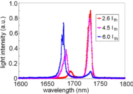
Figure 6. Lasing spectra of quantum wire lasers, which have cavities oriented perpendicular to the wires, at 140 K with different driving currents.
150 K is due to a switching from the ground state lasing to an excited state lasing. The increased temperature changes the Fermi distribution function and the homogeneous line shape of the wires. So at higher temperatures, the excited state takes over to have a higher gain and to be the lasing transition. For the lasers oriented parallel to the wires, the lasing wavelength at 20 K was 1.64 µm, which is much shorter than that of the lasers perpendicular to the wires. So clearly, the laser emission is not due to transition to the ground state. This is in agreement with the transition matrix calculation, which predicts a low transition rate to the heavy hole states for the E field perpendicular to the wires. The fact that the light emission is TE mode and the wavelength is short indicates that the laser light is probably from the thin wetting layer.
We have also noted that both the ground state and the excited state can lase at the same time in the transition region. Figure6shows the lasing spectra at different driving currents at 140 K. At low currents, there is only ground state lasing. As the current increases, the excited state starts to show up. As the current increases further, the excited state transition dominates the lasing spectrum. Clearly, after the ground state lases, the carrier density at the excited states continues to rise. Eventually the gain due to the excited state transition becomes higher and dominates the lasing spectrum. The simultaneous two-state lasing was also found for InAs QD lasers [18].
4. Conclusion
We have successfully demonstrated quantum wire lasers lasing in the 1.7 µm range using self-assembled InAs quantum wires on InP substrates. Obvious dependence on the cavity orientation, relative to the wire direction, was observed in the lasing behaviour. The difference in lasing threshold and spectrum for lasers oriented parallel and perpendicular to the wires agrees with polarization preference of the optical transitions in 1D quantum structures.
Acknowledgments
This study was supported by the National Science Council under contract no. NSC92-2120-E009-002. The authors would like to thank Dr G R Lin of the Opto-Electronics & Systems Laboratories in ITRI for technical help. The measurement supports in AFM and high resolution x-ray diffractometer from the Center of Nano Science and Technology of National Chiao Tung University are also appreciated.
References
[1] Leonard D, Pond K and Petroff P M 1994 Phys. Rev. B
50 11687
[2] Grundmann M, Ledentsov N N, Stier O, Bohrer J, Bimberg D, Ustinov V M, Kop’ev P S and Alferov ZhI 1996 Phys. Rev. B53 R10509
[3] Daruka I and Barabasi A-L 1997 Phys. Rev. Lett.79 3798
[4] Kirstaedter N et al 1994 Electron. Lett.30 1416
[5] Shoji H, Nakata Y, Mukai K, Sugiyama Y, Sugawara M, Yokoyama N and Ishikawa H 1996 Electron. Lett.32 2023
[6] Mirin R, Gossard A and Bowers J 1996 Electron. Lett.32 1675
[7] Xu S J et al 1999 Appl. Phys. Lett.73 3153
[8] Wang S Y, Lin S D, Wu H W and Lee C P 2001 Appl. Phys. Lett.78 1023
[9] Gutierrez H R, Cotta M A and de Carvalho M M G 2001 Appl. Phys. Lett79 3854
[10] Hanxuan Li, Daniels-Race T and Hasan M-A 2002 Appl. Phys. Lett.80 1367
[11] Sun Z, Yoon S F, Wu J and Wang Z 2002 J. Appl. Phys.
91 6021
[12] Mensing T, Worschech L, Schwertberger R, Reithmaier J P and Forchel A 2003 Appl. Phys. Lett.82 2799
[13] Lin S D, Lee C P, Hsieh W H and Suen Y W 2002 Appl. Phys. Lett.81 3007
[14] Poulain M 1998 Infrared glass optical fibers and their applications Lasers and Materials in Industry and Opto-Contact Workshop (SPIE-Int. Soc.) vol 3416 (Quebec, Canada) p 2
[15] Ohtoshi T, Kuroda T, Niwa A and Tsuji S 1994 Dependence of optical gain on crystal orientation in surface-emitting lasers with strained quantum wells Appl. Phys. Lett.65 1886
[16] Fiedler U, Reiner G, Schnitzer P and Ebeling K 1996 IEEE Photonics Technol. Lett.8 746
[17] Corzine S W, Yan R H and Coldren L A 1993 Quantum Well Lasers ed P S Zory Jr (San Diego, CA: Academic) [18] Markus A, Chen J X, Paranthoen C, Fiore A, Platz C and
Gauthier-Lafaye O 2003 Appl. Phys. Lett.82 1818