國
立
交
通
大
學
資訊學院 資訊學程
碩
碩
碩
碩
士
士
士
士
論
論
論
論
文
文
文
文
以視覺化使用者介面建構方法論應用於儲存系統之
人機介面設計及實作
Using Visual-Based User Interface Construction Methodology
for the Man Machine Interface Design and Implementation of
Storage Systems
研 究 生:黃承一
指導教授:陳登吉 博士
以視覺化使用者介面建構方法論應用於儲存系統之
人機介面設計及實作
Using Visual-Based User Interface Construction Methodology
for the Man Machine Interface Design and Implementation of
Storage Systems
研
究 生:黃承一
Student:Cheng-Yi Huang
指導教授:陳登吉
博士
Advisor:Deng-Jyi Chen
國
立 交 通 大 學
資
訊 學 院 資 訊 學 程
碩
士 論 文
A Thesis
Submitted to College of Computer Science
National Chiao Tung University
in Partial Fulfillment of the Requirements
for the Degree of
Master of Science
in
Computer Science
July 2007
Hsinchu, Taiwan, Republic of China
以視覺化使用者介面建構方法
以視覺化使用者介面建構方法
以視覺化使用者介面建構方法
以視覺化使用者介面建構方法論
論
論
論應用於儲存系統之
應用於儲存系統之
應用於儲存系統之
應用於儲存系統之
人機介面設計及實作
人機介面設計及實作
人機介面設計及實作
人機介面設計及實作
學生
學生
學生
學生:
:黃承一
:
:
黃承一
黃承一
黃承一
指導教授
指導教授:
指導教授
指導教授
:
:
:陳登吉
陳登吉
陳登吉
陳登吉
博士
博士
博士
博士
國
國
國
國 立
立
立 交
立
交
交
交 通
通
通 大
通
大 學
大
大
學
學
學 資
資
資
資 訊
訊
訊
訊 學
學 院
學
學
院
院 資
院
資
資 訊
資
訊
訊
訊 學
學 程
學
學
程
程 碩
程
碩
碩
碩 士
士
士
士 班
班
班
班
摘
摘
摘
摘 要
要
要
要
使用傳統的人機介面開發方法,當需求規格改變時,程式設計師必須
更改人機介面相關的程式。因此在開發與維護人機介面的程式,需要花費
大量的時間與人力。
本校資工系的軟體工程實驗室,已經發展出視覺化使用者介面建構方
法論,可以提昇人機介面軟體的生產力、品質及可維護性。本研究將應用
此方法論於儲存系統之人機介面設計及實作上,以克服傳統方法會遇到的
難題。
儲存系統之人機介面有其獨特性與多樣性,我們將設計出適合於儲存
系統之視覺化人機介面開發方法,其中包含視覺化編輯過程以及可用於儲
存系統之通用型人機介面引擎。
為了驗證此開發流程的可行性,我們實作一個軟體框架,內含通用型
人機介面引擎,可操作視覺化編輯工具產生的資料,並與儲存系統之管理
程式庫互動,以控制一個實際的儲存系統裝置介面卡。藉由此系統的建立
亦可驗證視覺化使用者建構方法論的可行性及應用性。
關鍵字
關鍵字
關鍵字
關鍵字:
:
:
:視覺化
視覺化
視覺化
視覺化、
、
、
、使用者介面
使用者介面、
使用者介面
使用者介面
、
、
、人機介面
人機介面
人機介面
人機介面、
、
、
、儲存系統
儲存系統
儲存系統
儲存系統
Using Visual-Based User Interface Construction Methodology
for the Man Machine Interface Design and Implementation of
Storage Systems
Student: Cheng-Yi Haung Advisor: Dr. Deng-Jyi Chen
Degree Program of Computer Science
National Chiao Tung University
Abstract
When the requirements of Man Machine Interface (MMI) are changed, programmers must change the related programs of MMI if they use the conventional MMI development. Therefore, they have to take long time to develop and spend much effort to maintain programs of MMI.
The Software Engineering Laboratory of NCTU had developed Visual-Based User
Interface Construction Methodology. This methodology can improve the productivity, quality, and maintainability of MMI software. In this thesis, we use this methodology for the MMI design and implementation of storage systems, and try to conquer UI problems using conventional MMI development.
For the typical and various Man Machine Interfaces of storage systems, we design the
Visual MMI Development for Storage Systems. It includes Visual Authoring Process and
Generic MMI Engine for storage systems.
In order to demonstrate the feasibility of the Visual MMI Development for Storage
Systems, we implement a software framework with Generic MMI Engine that can manipulate the output data of Visual Authoring Tool, interact with the Management API of storage systems, and use this system to control a functional storage adapter. A real application example using the proposed approach is applied to demonstrate the applicability of the methodology.
誌
誌
誌
誌 謝
謝
謝
謝
在累積工作經驗後,重回母校進修,不僅在研習過程中的想法與目標
更為明確、對學術研究有更深入的理解與啟發,並自我期許能學以致用,
在實務領域有更進一步的助益。
本論文的完成,首先要感謝 陳登吉老師不辭辛勞的指導與教誨,才
得以順利付梓。老師一向認真堅毅的態度,是學生們最好的身教。同時亦
感謝論文口試委員,蕭嘉宏教授、陳振炎教授、黃俊龍教授,提供許多寶
貴的意見及精闢的建議,使得此論文未臻完備之處得以補正。
論文研究期間,承蒙蔡明志學長的勉勵與指教,以及翁浚恩、張正隆
等同學們諸多的協助與相互扶持,還有工作上長官與同事們的分憂解勞,
才能在學業與工作的雙重壓力之下,如期的完成此篇論文。
最後,我必須感謝最親愛的父親、母親與妻子婷婷,在我求學過程中
無限的體諒與支持,是我能完成學業的依靠。有你們對我的期望與鼓勵,
是我不斷向前進步的原動力。
黃承一 謹誌
交通大學 資訊學院 資訊學程碩士班
中華民國九十六年八月
Contents
Abstract in Chinese...I Abstract...II Acknowledgement in Chinese...III Contents... IV List of Figures... VI
List of Tables...1
Chapter 1 Introduction...1
1.1 Overview of Storage Systems...1
1.2 Man Machine Interfaces of Storage Systems...2
1.3 Motivation and Goal of This Thesis...5
Chapter 2 Related Work...7
2.1 Conventional MMI Development...7
2.2 Visual-Based UI Construction Methodology...8
2.3 Conventional Software Framework for MMIs of Storage Systems...13
Chapter 3 System Design and Implementation...16
3.1 Visual MMI Development for Storage Systems...16
3.2 Generic Software Framework for the MMI Generation of Storage Systems...20
3.3 Implementation of Visual MMI Development for Storage Systems...21
3.3.1 Visual Authoring Tool -- Inkscape...22
3.3.2 SVG Files...24
3.3.3 SVG Parser...26
3.3.4 MMI Data...30
3.3.5 Generic MMI Engine...37
Chapter 4 Simulation and Application Examples...41
4.1 Simulation Examples for the Booting Utility of Storage Systems...41
Chapter 5 Conclusion and Future Work...50
5.1 Conclusion of This Thesis...50
5.2 Future Work...52
Reference...53
Appendix A External Storage system...54
A.1 DAS (Direct Attached Storage)...54
A.2 SAN (Storage Area Network)...55
A.3 NAS (Network Attached Storage)...56
A.4 Comparison of DAS / SAN / NAS...57
Appendix B Application Instances of Inkscape...59
B.1 Creating Vector Graphics...59
B.2 Producing Comics and Maps...62
B.3 Design of Web Pages...63
List of Figures
Figure 1. The Classification of Storage Systems...1
Figure 2. Man Machine Interfaces of Storage Systems...3
Figure 3 Various MMIs for Serial Products and Different Customers...6
Figure 4. The Waterfall Model for Software Process...7
Figure 5. The Concept of Conventional MMI Development ...8
Figure 6. The Concept of Visual-Based UI Construction Methodology...9
Figure 7. The Framework of Visual-Based UI Construction Methodology...10
Figure 8. Comparisons between Conventional and Visual-based UI Construction [7]...12
Figure 9. Conventional Software Framework for MMIs of Storage Systems...14
Figure 10. The Concept of Visual MMI Development for Storage Systems ...16
Figure 11. The Framework of Visual MMI Development for Storage Systems ...17
Figure 12. Generic Software Framework for the MMI Generation of Storage Systems ...20
Figure 13. Visual Authoring Process...22
Figure 14. Visual Authoring Tool -- Inkscape ...23
Figure 15. Edit SVG File in the XML Editor of Inkscape ...24
Figure 16. XML in Plain Text ...27
Figure 17. XML DOM ...28
Figure 18. Expat XML Parser...29
Figure 19. MmiData.h – The Output File of SVG Parser...31
Figure 20. The Block Diagram of Generic MMI Engine ...38
Figure 21. MMI Requirement Specification for Simulation and Application Examples...41
Figure 22. Compose Screen Layout by Inkscape ...42
Figure 23. SVG File in Plain Text...43
Figure 24. Compose the Template SVG File ...44
Figure 25. Compose Menus by Using the layer_MenuTemple...45
Figure 26. Simulation Examples for the Booting Utility of Storage Systems...47
Figure 27. Application Examples for the Pre-OS Utility of Storage Systems ...48
Figure 28. Visual Authoring Process of Visual MMI Development for Storage Systems...50
Figure 29. Generic MMI Engine for the MMI Generation of Storage Systems...51
Figure 30. DAS (Direct Attached Storage) ...54
Figure 31. SAN (Storage Area Network) ...55
Figure 32. NAS (Network Attached Storage) ...56
Figure 33. Comparison DAS / SAN / NAS ...57
Figure 34. Complex Vector Graphics...59
Figure 35. Photo-realistic Graphic...60
Figure 36. Advanced Graphic Effects ...61
Figure 37. Producing Comics ...62
Figure 38. Producing Maps ...63
List of Tables
Table 1. The Dependences of Storage Systems and Their MMIs ...5
Table 2. Implement MMI Elements by SVG Elements...26
Table 3. SVG Parser Uses Functions of Expat XML Parser ...29
Chapter 1
Introduction
In this chapter, we introduce and overview storage systems with their typical and various Man Machine Interfaces. Also, the motivation and goal of this thesis study are addressed.
1.1 Overview of Storage Systems
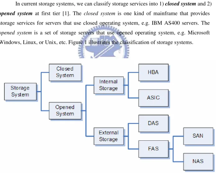
In current storage systems, we can classify storage services into 1) closed system and 2)
opened system at first tier [1]. The closed system is one kind of mainframe that provides
storage services for servers that use closed operating system, e.g. IBM AS400 servers. The
opened system is a set of storage servers that use opened operating system, e.g. Microsoft Windows, Linux, or Unix, etc. Figure 1 illustrates the classification of storage systems.
For opened system, we divide storage devices into 1) internal storage and 2) external
storage at second tier by the connections between servers and storage devices.
There are two types of internal storage systems: HBA (Host Bus/Based Adapter) and
ASIC (Application Specific Integrated Circuit). The administrator of servers can insert one or
more standalone HBA adapters into the slots on server board to increase the capability to connect more hard disk drives. On the other hand, more and more chipsets are integrated with RAID (Redundant Array of Independent/Inexpensive Disks) controller or storage ASIC so that they also have the capability to connect many hard disk drives.
For external storage systems, there are also two types: DAS (Direct Attached Storage) and FAS (Fabric Attached Storage). The DAS devices usually use the SCSI bus as the external connection to the servers. Most of high-end DAS devices are the subsystems that run embedded operating system and can handle dozen of hard disk drives.
To describe FAS more clearly, we can separate it into SAN (Storage Area Network) and NAS (Network Attached Storage). Many SAN storage systems use fiber channel as the transfer media, and need a fiber channel switch to connect many devices in the same storage area network. On the contrary, the NAS storage systems use the popular Ethernet in the same local area network, and computers can share the NAS storage systems very easily.
About more details of external storage systems, please refer to Appendix A External Storage system.
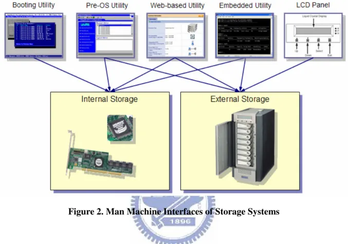
1.2 Man Machine Interfaces of Storage Systems
No matter internal or external storage systems, they must have Man Machine Interfaces (MMI) so that users can configure and manage them. For example, users can get a list of physical hard disk drives in the storage system, and group up some of them to make up a disk array in one kind of RAID (Redundant Array of Independent/Inexpensive Disks) level.
After survey the products of storage systems in current market, we sum up them and generalize five kinds of Man Machine Interfaces for storage systems. They are 1) Booting
Figure 2 illustrates these five kinds of MMI for storage systems and the dependences of internal and external storage systems on them.
Figure 2. Man Machine Interfaces of Storage Systems
We describe these five kinds of MMI for storage systems as below.
1) Booting Utility: Users can use the Booting Utility to configure hard disk drives and setup bootable drivers before OS is loaded. Usually, this utility is included in the expansion ROM of BIOS (Basic Input Output System) or EFI (Extensible Firmware Interface) [2] driver of storage HBA adapters. When system BIOS or EFI firmware boots up system, they will load the BIOS ROM or EFI driver of the storage HBA adapter into memory and run. The BIOS ROM or EFI driver will prompt some messages to tell users how to enter the Booting Utility. After users press a certain combination of hotkeys, they can enter this utility and manage storage devices. For example, users can select wanted hard disk drives to create a disk array in RAID (Redundant Array of Independent/Inexpensive Disks) level 1 or 5 with fault tolerance. The most particular functionality of the Booting Utility is it can tell system BIOS that which logical drives in the storage system can become bootable drives. However, this
kind of utility usually provides basic functions of storage systems because of the limitation of code and data size.
2) Pre-OS Utility: This kind of utility is used in Pre-OS environments, e.g. DOS (Disk Operation System), EFI (Extensible Firmware Interface) shell, or Windows PE (Pre-installation Environment). Many large corporations use Pre-OS environments for the deployment of workstations and servers. Original Equipment Manufacturers (OEM) also use these environments to preinstall Windows client operating systems to personal computers or laptop and notebook computers during manufacturing. The Pre-OS Utility of storage systems has similar functionalities to the Booting Utility. The advantage of Pre-OS Utility is that users can run it at any time without system reboot.
3) Web-based Utility: The Web-based Utility uses web pages as user interfaces. Since many years ago, almost every operating system provides at least one web browser for network surfing. The advantage of the Web-based Utility is that end users can connect to this kind of utility with web browser conveniently. They do not need to install any client application. Therefore, more and more storage system companies adopt the Web-based Utility for their products.
4) Embedded Utility: Numerous storage systems apply the architecture of embedded system, and engineers usually use a serial cable to connect the console of embedded system. Engineers can use the Embedded Utility to setup advanced configuration or debug internal problems. This kind of utility is running in the embedded operating system. However, the serial console of embedded system and the Embedded Utility use the command-based or menu-based user interfaces. They are not user-friendly. Now, the Embedded Utility is not a popular MMI of storage systems for end users.
5) LCD Panel: Some high-end storage systems have the LCD Panel at their faceplate or front-plane. The maintenance people can use the LCD Panel conveniently to verify new configuration, because these storage systems are usually in one isolated room for security reason. The LCD Panel has the related programs that run in the embedded operating system, too.
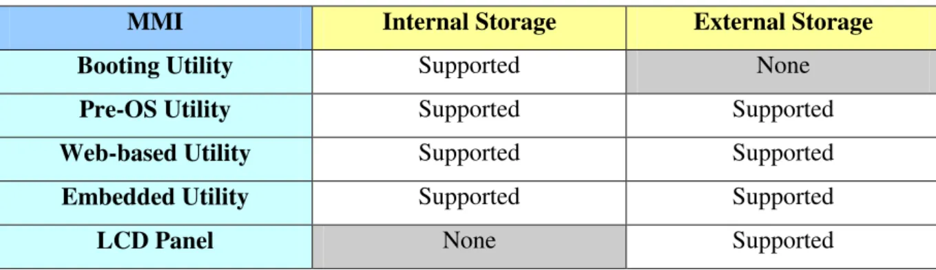
We describe the dependences of internal and external storage systems on these five kinds of MMI for storage systems in Table 1.
Table 1. The Dependences of Storage Systems and Their MMIs
MMI Internal Storage External Storage
Booting Utility Supported None
Pre-OS Utility Supported Supported
Web-based Utility Supported Supported
Embedded Utility Supported Supported
LCD Panel None Supported
Table 1 lists the dependences of storage systems and their Man Machine Interfaces. For internal storage systems, they have four supported man machine interfaces: 1) Booting
Utility, 2) Pre-OS Utility, 3) Web-based Utility, and 4) Embedded Utility. For external storage
systems, they also have four supported man machine interfaces: 1) Pre-OS Utility, 2)
Web-based Utility, 3) Embedded Utility, and 4) LCD Panel.
Because internal storage systems are one part of host servers, they do not have the
LCD Panel. On the other hand, external storage systems do not take the responsibility to boot up host servers, the Booting Utility is not necessary for them.
1.3 Motivation and Goal of This Thesis
The conventional approach to develop Man Machine Interfaces for storage system has limited flexibility while the MMI requirement is changed. During development phase, programmers have to change their handcrafted MMI application code again once the MMI requirement is changed. This change may occur repeatedly until the MMI requirement under consideration is satisfied.
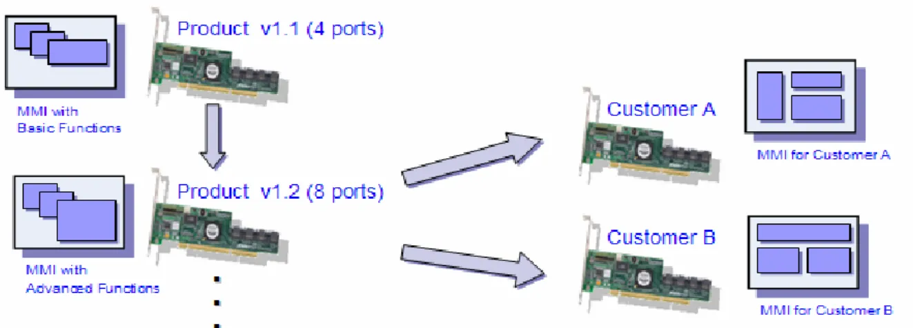
For instance, we can study the cases in figure 3. The case on the left side is the MMI development for serial products, and the case on the right side is the MMI maintenance for different customers.
Figure 3 Various MMIs for Serial Products and Different Customers
1) For the case on the left side of figure 3: The MMI requirement for product version 1.1 (with 4 ports to connect hard disk drives) only requires basic functions of the storage system, while the MMI requirement for product version 1.2 (with 8 ports to connect hard disk drives) requires additional advanced functions. MMI designers have to change the menu size to support more ports for more hard disk drives, and more advanced functions for the new serial products. Consequently, MMI programmer must modify their MMI programs to meet these changes.
2) For the case on the right side of figure 3: Different customers bought the same kind of product. Customer A wants to change the layout of MMI into layout A, while customer B wants his layout of MMI in layout B. Since layout A and B are different, the MMI designers and programmers must maintain various MMI programs for these different customers eventually.
Unfortunately, the time to market is usually very short and the human resource to develop and maintain products is very tight, how to shorten the MMI development time and reduce maintenance effort become a major issue for the market competition.
In this thesis study, we attempt to conquer above problems by using Visual-Based UI
Construction Methodology to design the Visual MMI Development for Storage Systems. After
the construction of this system, we also demonstrate the feasibility and applicability of the
Chapter 2
Related Work
In this chapter, we describe the related work of conventional MMI development, the
Visual-Based UI Construction Methodology, and the conventional software framework for MMIs of storage systems.
2.1 Conventional MMI Development
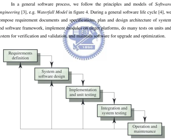
In a general software process, we follow the principles and models of Software
Engineering [3], e.g. Waterfall Model in figure 4. During a general software life cycle [4], we compose requirement documents and specifications, plan and design architecture of system and software framework, implement modules on target platforms, do many tests on units and system for verification and validation, and maintain software for upgrade and optimization.
Figure 4. The Waterfall Model for Software Process
Requirements definition
System and software design
Implementation and unit testing
Integration and system testing
Operation and maintenance
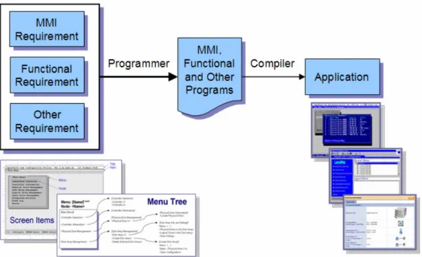
Figure 5. The Concept of Conventional MMI Development
In the brief illustration of figure 5, the concept of conventional MMI development [5], MMI designers have to compose MMI requirement documents with screen layouts or menu tree, etc, and system designers compose functional and other requirement documents. According to these requirement documents, programmers implement MMI, functional and other programs, and compile them together and produce applications. However, these applications are implemented for specific environments, e.g. Booting Utility in BIOS / EFI environment, Pre-OS Utility in EFI Shell or Win-PE environments. It is hard to design reusable programs for all MMI utilities of storage systems. Usually their MMI programs mix with functional programs and others. Therefore, programmers have to take long time to modify, or develop new programs when MMI requirements were changed. Also, we need much effort to maintain these utilities for serial products and various customers.
2.2 Visual-Based UI Construction Methodology
The Software Engineering Laboratory of NCTU had developed Visual-Based User
Interface Construction Methodology [6]. We illustrate the concept of this methodology in
Figure 6. The Concept of Visual-Based UI Construction Methodology
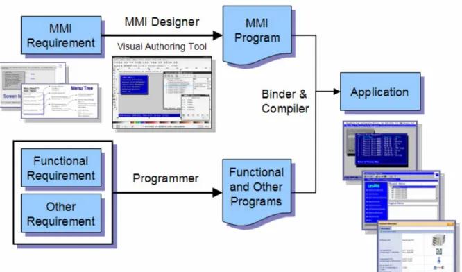
In this methodology, MMI designers use visual authoring tool to compose MMI prototype according to MMI requirements. The visual authoring tool can generate MMI programs. Programmers implement functional and other programs as API library for MMI programs. We can bind the related functions to MMI components, and then produce application utilities very efficiently.
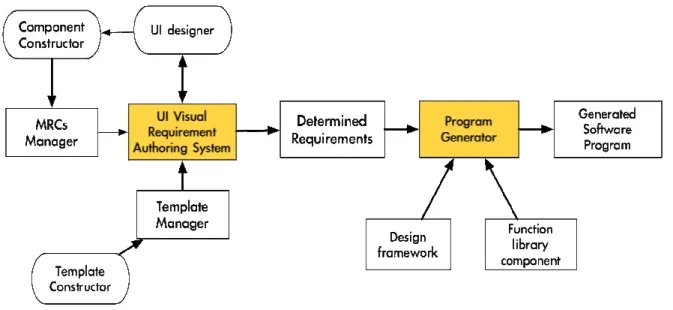
Figure 7 illustrates the detail framework of Visual-Based User Interface Construction
Methodology. This methodology supports the UI Visual Requirement Authoring System for UI designers to produce GUI-based requirement scenario and specifications. It also supports the Program Generator to generate the target application system as specified in the visual requirement representation. The programmer can produce the target application system, base on the function binding features provided in the program generator to bind each GUI component with the associated application function.
Figure 7. The Framework of Visual-Based UI Construction Methodology
The main components of this system are described as follows:
1) UI Visual Requirement Authoring System: It is a visual-based authoring tool. The UI designers use the UI Visual Requirement Authoring System to create a prototype of user look and feel. Then one can edit this prototype by adding more text or buttons. The UI designers can preview the prototype and modify it. Once the authoring process is completed, the UI designer has generated a target UI system.
2) MRCs Manager: MRC (Multimedia Reusable Components) is the basic component in visual requirement presentation, contains multimedia data by the object-oriented method. It has its own attributes, and accepts external signal to trigger actions. The UI designer uses the existing MRCs to produce the visual UI prototype via visual UI authoring tool. If there are no existing MRCs, the UI designer uses the component constructor to produce new MRCs and then adds it to the MRCs Manager for further use in the visual UI authoring tool.
3) Template Manager: It is a database management system for managing UI templates, e.g. structure template, layout template, and style template. It provides an interface for adding or deleting UI templates as well as for retrieving an existing UI template. Template constructor can make new UI templates and then stores them into UI template database through the Template Manager.
4) Program Generator: It is a function binding system that generates the program for target system based on the binding of a UI icon to an API function for the underlying device. When the design of user look and feel is satisfied, the UI designers use the program generator to produce the source code of application. The program generator produces the source code according to the visual representation generated by the Visual UI Authoring System. The program generator glues the UI components to the software design framework, and binds function library component with each UI component defined in the generated visual representation.
5) Design Framework: It is used to generate software system architecture for the target application system. The Program Generator applies the software framework to generate the source code. A software framework is a platform for representing the visual representation that is generated by the authoring system. Programmers can instantiate a software framework from the generic software framework.
6) Function Library Component: It is a set of pre-defined library. Programmers develop associated functions based on API (Application Program Interface) library functions, and implement them according to the hardware specification. The Program Generator applies this function library to produce source code for target UI system.
This UI Visual Requirement Authoring System is especially suitable for the UI designer. The visual-based authoring system helps the UI designers to create a prototype of MMI in an efficiency way. The UI designers can edit and preview this prototype and verify its functionality on PC. After the design of MMI is frozen, the UI designer can apply this authoring system to produce the target UI program without writing any textual code. The authoring system uses the code generator to translate the visual representation to source code. The code generator resolves the relationship between the MMI and the application functions of device drivers. It applies the designed framework and function library in code generation phase.
The Visual-Based User Interface Construction Methodology can improve the productivity, quality, and maintainability of MMI software efficiently [7]. This methodology claims for the following benefits:
1) Replace voluminous textual documentations
2) Support rich multimedia UI components such video, audio, image, and animation for UI designer to easily and quickly authoring visual UI prototype.
3) Generate visual MMI prototype without writing textual based program 4) Independent work between MMI designer and programmer
5) Provide more natural means of communication to reduce misunderstanding between MMI designer and programmer
6) Based on the experiment results, it depicts that using this methodology can reduce the development and maintenance time during the construction of MMI system [7] 7) Elicit an early feedback from user, more expressive in describing user’s demands 8) Based on the experiment results, it depicts that using the proposed methodology can
reduce the development and maintenance time during the construction of UI system
In figure 8, some experimental data in the dissertation, “Generating User Interface for
Mobile Devices Using Visual-Based User Interface Construction Methodology” [7], are recalled here.
Figure 8. Comparisons between Conventional and Visual-based UI Construction [7]
In the left chart of figure 8, the experiment results compare the development time between the Conventional MMI Development and Visual-Based User Interface Construction
Methodology. Based on the collected data, the upper line with circle dots represents the development time that students use the Conventional MMI Development, and the average time spent is 420 minutes. The lower line with square dots represents the development time that
students use Visual-Based User Interface Construction Methodology, and the average time spent is 376 minutes.
In the right chart of figure 8, the experiment results compare the maintenance time between the Conventional MMI Development and Visual-Based User Interface Construction
Methodology. The upper line with circle dots represents the maintenance time that students use the Conventional MMI Development, and the average time spent is about 154 minutes. The lower line with square dots represents the maintenance time that students use
Visual-Based User Interface Construction Methodology, and the average time spent is about 140 minutes.
Both charts in figure 8 reveal the development and maintenance time of Visual-Based
User Interface Construction Methodology are less than the Conventional MMI Development.
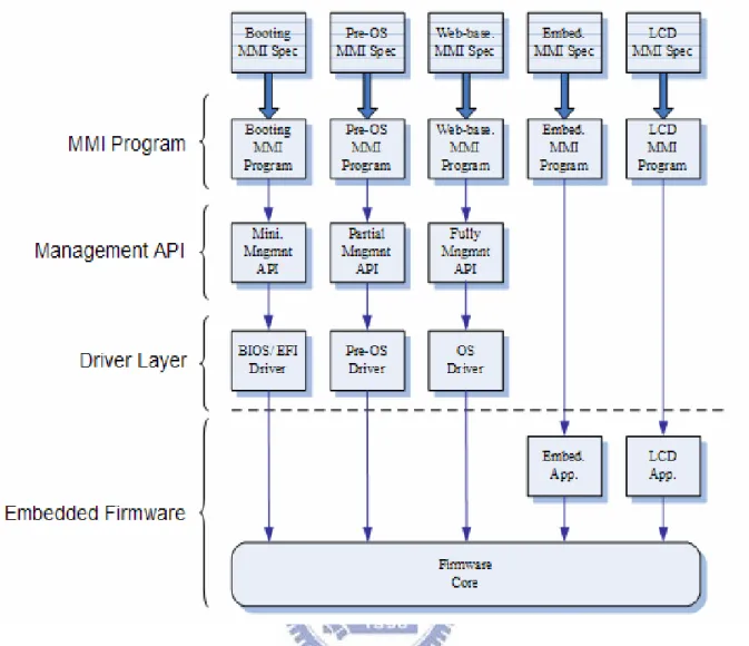
2.3 Conventional Software Framework for MMIs of Storage Systems
We analyze conventional software framework for MMIs of storage systems, and generalize four layers: 1) MMI Program, 2) Management API, 3) Driver Layer, and 4)
Embedded Firmware.
Here is a short example to describe the relationship between these layers. The end-users use the MMI Program to display the information or configuration of storage systems. Before MMI Program displays these data, it calls the functions of Management API to get the particular data, and then it arranges the data into the display screen. Management API is a function library, and its functions can submit management commands to get the information or set the configuration of storage systems. These commands will pass to Driver Layer because this is the software layer to transfer commands to hardware devices. In the internal side of storage systems, Embedded Firmware handles commands from host side and response them with particular results.
Figure 9 illustrates the Conventional Software Framework for MMIs of Storage
Figure 9. Conventional Software Framework for MMIs of Storage Systems
We describe these four layers in the following paragraphs.
1) MMI Program: According to MMI specifications, programmers implement MMI programs for particular utilities. For instance, they implement the MMI program in assembly language for Booting Utility, C language for Pre-OS Utility, Java for Web-based Utility, etc. These MMI Programs call Management API to get information or change the setting of storage systems. For Embedded Utility and LCD Panel of storage systems, there are related applications embedded in firmware side.
2) Management API: Management API is a library with many functions for utilities to get information, fetch strings, or change the setting of storage systems. For example, function
MngApi_GetCtrlInfo( ) can get controller information, and function MngApi_GetPdInfo( ) can get physical drive information. The other functions can set logical driver’s cache policy, etc.
First, the Booting Utility of storage systems includes basic functions only, so it usually uses minimal Management API. Second, the Pre-OS Utility is similar to Booting Utility, but it includes some advanced functions, and needs some additional Management API for these advanced functions. Third, the Web-based Utility includes full functions of storage systems, and of course, it uses full Management API of storage systems.
3) Driver Layer: Driver provides the capability to submit commands to hardware devices. Usually Management API submits a set of management commands, or called IOCTRL (IO Control) commands, to Driver Layer. No matter BIOS / EFI driver, Pre-OS driver or OS driver will pass these commands to the embedded firmware of storage systems.
4) Embedded Firmware: In the internal side of storage systems, there are embedded operating system and firmware core running. Firmware core handles commands from host side, transfer data to the buffer of Management API by DMA (Direct Memory Access), and return the status of commands to host drivers. For Embedded Utility and LCD Panel of storage systems, the related applications are running in embedded OS also.
Before MMI programs display the information of storage systems, they must call the functions of Management API to get the wanted information. Management API provides many functions for MMI programs and submits management commands to firmware by passing through the Driver Layer to get data. Driver passes management commands to firmware and returns the status of commands for Management API. Embedded firmware takes the responsibility to handle management commands and take the actions for them. For example, Embedded Firmware collects information of adapter controller or hard disk drives, or changes the setting of disk array, etc.
Chapter 3
System Design and Implementation
In this chapter, we describe the design and implementation of the Visual MMI
Development for Storage Systems, and derive the Generic Software Framework for the MMI
Generation of Storage Systems.
3.1 Visual MMI Development for Storage Systems
In this section, we design the model of Visual MMI Development for Storage
Systems. This model uses similar concept of Visual-Based User Interface Construction
Methodology, MMI designers use visual authoring tool to compose MMIs, and programmers write functional and other programs separately. Figure 10 illustrates this concept.
However, the difference between Visual-Based UI Construction Methodology and
Visual MMI Development for Storage Systems is the output of the Visual Authoring Process. In the previous methodology, Visual Authoring Tool generates MMI program, and programmer binds functions from functional library to MMI program and generate MMI applications.
We change the output of the Visual Authoring Process becomes MMI data, and let
Generic MMI Engine to manipulate this MMI data directly. This change is due to the consideration on some limitations for MMI utilities of storage systems. With this change, we can implement the Generic MMI Engine for various environments.
Figure 11 illustrates the framework of Visual MMI Development for Storage Systems.
This framework includes the following major parts:
1) Visual Authoring Tool: MMI designers use the Visual Authoring Tool to compose wanted MMIs according to MMI requirement documents. During implementation, we choose Inkscape as this tool. Please refer to section 3.3.1 Visual Authoring Tool -- Inkscape.
2) SVG Files: These files are the output of Visual Authoring Tool. We use the file format in SVG (Scalable Vector Graphics) that is a standard language to describe two-dimensional graphics and graphical applications in XML (Extensible Markup Language). Please refer to section 3.3.2 SVG Files.
3) Template SVG Files: These files are the SVG files with templates of MMI elements. To speed up the development of MMIs, we can create these files for MMI designers first. All SVG files can be previewed in some web browsers, e.g. Firefox.
4) SVG Parser: This parser can parse the SVG structure, and obtain required information from SVG files. It invokes some functions of XML parser. Please refer to section 3.3.3 SVG Parser.
5) MMI Data: The output data of SVG Parser is MMI Data. It is also the results of
Visual Authoring Process. Generic MMI Engine can manipulate the MMI Data directly. Please refer to section 3.3.4 MMI Data.
6) Generic MMI Engine: This is the kernel component of Visual MMI Development
for Storage Systems. It needs the Management API and OS Dependent API to accomplish the functionalities of target MMI application. Please refer to section 3.3.5 Generic MMI Engine.
7) Management API: This API (Application Program Interface) is depended on the features of storage systems, and it provides functions to manage underlying storage devices. MMI programmers have to program these functions according to functional requirement documents, and Generic MMI Engine will invoke these functions.
8) OS Dependent API: Generic MMI Engine requires some functional APIs but they are OS dependent. For instance, it needs Input API to get the input of keyboard or mouse, and
Display API to display the MMIs to the monitor screen of computers. We separate the OS dependent code to OS Dependent API, and let the implementation of Generic MMI Engine become more easily for various environments.
9) Target MMI Application: After MMI designers compose MMIs with Visual
Authoring Tool, save them as SVG files, and use SVG Parser to transform SVG files to MMI
data, we can generate target MMI application with MMI data, Generic MMI Engine,
Management API and OS Dependent API.
To use the model of Visual MMI Development for Storage Systems, we describe its flow in the following steps:
Step 1) MMI designers use Visual Authoring Tool to compose wanted MMIs according to MMI requirement documents
Step 2) Save the results of Visula Authoring Tool as SVG Files.
Step 3) To speed up the development of MMIs, we can create Template SVG Files for MMI designers.
Step 4) For developers or customers, they can preview these SVG Files in web browsers.
Step 5) MMI programmers add additional information in SVG Files.
Step 6) Use SVG Parser to transform SVG Files to MMI Data.
Step 7) MMI programmers program related functions in Management API according to functional requirement documents.
Step 8) Generate the target MMI applications with MMI Data, Generic MMI Engine,
3.2 Generic Software Framework for the MMI Generation of Storage
Systems
The conventional software framework for the MMI generation of storage systems lacks of the support of a visual authoring system. We therefore incorporate a visual authoring system into the software framework for MMIs of storage systems. The incorporated Visual
Authoring and MMI Engine are shown in figure 12. We call the new software framework as
Generic Software Framework for the MMI Generation of Storage Systems, since it can be
used to generate Man Machine Interfaces of many storage systems.
There are also four layers in Generic Software Framework for the MMI Generation of
Storage Systems: 1) Visual Authoring Process, 2) Generic MMI Engine, 3) Driver Layer, and 4) Embedded Firmware. We introduce the new layers:
1) Visual Authoring Process: MMI designers use Visual Authoring Tool to compose each MMI according to the MMI requirement specification for particular utility. The authoring tool is visualized and very user-friendly. After save the results in SVG files and use
SVG Parser to parse these files, we can get the MMI data for Generic MMI Engine at the end of Visual Authoring Process. For instance, MMI designers use Visual Authoring Tool to compose the MMIs of Booting Utility and Pre-OS Utility, and then generate the Booting MMI
Data and Pre-OS MMI Data.
2) Generic MMI Engine: Programmers do not need to write any MMI programs, but they have to program the related functions for MMIs. We design the Generic MMI Engine as common code, and it invokes these MMI related functions. This engine also cooperates with the Management API of storage systems. The design of Generic MMI Engine is OS independent, and we separate the OS dependent functions to OS Dependent APIs. This design is helpful to implement utilities in various environments.
The 3) Driver Layer and 4) Embedded Firmware are the same as the ones in the conventional software framework for MMIs of storage systems.
After MMI designers finish the Visual Authoring Process and programmers write the related functions for MMIs, we can come out the particular utility for storage systems with the
MMI Data, Generic MMI Engine, and Management API. This utility still needs Driver Layer to pass commands to Embedded Firmware of storage systems.
3.3 Implementation of Visual MMI Development for Storage Systems
To implement the Visual MMI Development for Storage Systems, we must consider five key components: 1) Visual Authoring Tool – Inkscape, 2) SVG Files, 3) SVG Parser, 4)
The first phase of Visual MMI Development for Storage Systems is Visual Authoring
Process. We illustrate this procedure in figure 13, and describe the details of this process in the following sections.
Figure 13. Visual Authoring Process
3.3.1 Visual Authoring Tool -- Inkscape
In our implementation, we choose Inkscape [12] as Visual Authoring Tool. Inkscape is an open source vector graphics editor, with capabilities similar to Illustrator, Freehand, CorelDraw, or Xara X using the W3C [13] standard Scalable Vector Graphics (SVG) file format. Supported SVG features include shapes, paths, text, markers, clones, alpha blending, transforms, gradients, patterns, and grouping. Inkscape also supports Creative Commons meta-data, node editing, layers, complex path operations, bitmap tracing, text-on-path, flowed text, direct XML editing, and more. It imports formats such as JPEG, PNG, TIFF, and others and exports PNG as well as multiple vector-based formats.
The main goal of Inkscape is to create a powerful and convenient drawing tool fully compliant with XML, SVG, and CSS standards. Therefore, it is very suitable for the Visual
Authoring Process of Visual MMI Development for Storage Systems.
Figure 14. Visual Authoring Tool -- Inkscape
MMI designers can use the Graphic Tools, Canvas, and Layers Manager of Inkscape to implement MMIs for storage systems. To simplify and formalize the implementation of MMIs for storage systems, we use Graphic Tools to create rectangles and texts only, and put them in the Canvas area. To compose more complex vector graphics, MMI designers can use the Layer Manager to overlap many layers of graphics.
On the other hand, MMI programmers can use the XML Editor of Inkscape to modify SVG files conveniently. They can modify the name, attributes of SVG elements, and define the relationship between lots of SVG elements, or add the related functions in the functional or other programs into SVG elements.
Figure 15 illustrates one SVG file in plan text and the XML Editor of Inkscape. We recommend MMI programmers to use the XML Editor of Inkscape to add information in SVG files.
Figure 15. Edit SVG File in the XML Editor of Inkscape
To implement man machine interfaces by Visual Authoring Process, MMI designers or programmers are free to learn the SVG language. MMI designers use Inkscape to compose wanted MMI graphics and save them to the files in SVG format. When programmers want to modify the SVG files, they do not need to handcraft the SVG file in plain text. On the contrary, programmers can use the XML editor of Inkscape to edit SVG file easily and user-friendly.
3.3.2 SVG Files
SVG (Scalable Vector Graphics) [14] is a language for describing two-dimensional
graphics and graphical applications in XML (Extensible Markup Language) [15]. XML is a simple, very flexible text format derived from SGML (ISO 8879). Originally designed to meet the challenges of large-scale electronic publishing, XML is also playing an increasingly important role in the exchange of a wide variety of data on the Web and elsewhere.
SVG is used in many business areas including Web graphics, animation, user interfaces, graphics interchange, print and hardcopy output, mobile applications and high-quality design. It has two parts: an XML-based file format and a programming API for graphical applications. Key features include shapes, text and embedded raster graphics, with many different painting styles. It supports scripting through languages such as ECMAScript and has comprehensive support for animation.
SVG is a royalty-free vendor-neutral open standard developed under the W3C Process. It has strong industry support; Authors of the SVG specification include Adobe, Agfa, Apple, Canon, Corel, Ericsson, HP, IBM, Kodak, Macromedia, Microsoft, Nokia, Sharp and Sun Microsystems. SVG viewers are deployed to over 100 million desktops, and there is a broad range of support in many authoring tools.
SVG builds upon many other successful standards such as XML (SVG graphics are text-based and thus easy to create), JPEG and PNG for image formats, DOM for scripting and interactivity, SMIL for animation and CSS for styling.
SVG is interoperable. The W3C release a test suite and implementation results to ensure conformance. Applications of SVG in industry are graphics platform for mobile phone, embedded system and print industry, web applications, design and interchange, GIS (Geographic Information Systems) and mapping, etc.
We adopt SVG files as the inter-media of Visual Authoring Process because SVG has above advantages. For example, we can preview the MMI in SVG files by web browser, and MMI programmers can add more information about MMI programs into SVG files conveniently. Furthermore, we can apply the functionality of XML parser to implement the specific SVG Parse very easily for the SVG files of MMI.
To simplify the implementation, we use three SVG elements, Layer, Rect and Text, to implement the MMI elements for storage systems. Please refer to the relationship between SVG elements and MMI elements in the following table. Using the same SVG element, we define one or more MMI elements with different attributes sot that we can manipulate them very conveniently in Generic MMI Engine.
Table 2. Implement MMI Elements by SVG Elements
SVG Elements MMI Elements
Layer Screen, Layer Rect Rect, Edge
Text Text, Title, Head, Cont, Navi, Msg, Node
1) Using SVG Layer element to implement Screen, Layer MMI elements: The Layer Manger of Inkscape can control SVG Layer element to display or hide, free-to-modify or lock-up. We define Screen element to compose the base screen layout, and Layer element to place one menu and its related components, e.g. some items in this menu, or help messages for it.
2) Using SVG Rect element to implement Rect, Edige MMI elements: The rectangle in SVG graphics can be solid or hollow rectangles. We use solid rectangle to define Rect MMI element that is used for menu’s body and shadow, and hollow rectangle to define Edge MMI element that is the edge or border of menu’s body.
3) Using SVG Text element to implement Text, Title, Head, Cont, Navi, Msg, Node MMI elements: The SVG Text element has many attributes, like font size or color. We use the same font size for all text MMI elements. Nevertheless, we define many text MMI elements with different colors. They are used for different purposes: The Text MMI element is a common string and can be used in base screen layer. The Title MMI element is used for the title of base screen or menus. The Head MMI element is used for the head of items in menus. The Cont MMI element is used for the content of items in menus. The Navi MMI element is used for the string on Navigation Bar. The Navigation Bar is the row between screen title and canvas and it can show the path of current menus. The Msg MMI element is used for the string on Message Bar. The Message Bar is the lowest row in screen and it can display the message for current menu. The latest and important MMI element, Node, can carry the information to child menu and the related function to take actions, but MMI programmers must add the child menu and related function for each Node manually.
After using Inkscape to create SVG files, we need a parser to parse SVG structure and obtain required information from SVG files. We call this parser as SVG Parser. Before describe the SVG parser, we introduce the concept of XML DOM (Document Object Model) first.
In the right part of figure 16, it is a simple XML in plain text. This XML describes a bookstore with a couple of books.
Figure 16. XML in Plain Text
Each book has four elements: title, author, year and price. For example, first book’s title is “Everyday Italian” in English language, because its attribute is lang=”en”, author is “Giada De Laurentiis”, year is 2005, price is 30.00. In the left part of figure 16, there is a tree to describe the hierarchy of that XML. It is very easy to understand compared with the plain text format.
Figure 17 illustrates a using example of XML DOM (Document Object Model) for the above XML of bookstore.
Figure 17. XML DOM
The Document Object Model is a platform- and language-neutral interface that will allow programs and scripts to dynamically access and update the content, structure and style of documents. The document can be further processed and the results of that processing can be incorporated back into the presented page..
Using XML DOM, a XML Parser can traverse the node tree, access the nodes and their attribute values, insert and delete nodes, and convert the node tree back to XML. In our implementation, we choose Expat XML Parser [19].
Expat is an XML parser library written in C. It is a stream-oriented parser in which an application registers handlers for things the parser might find in the XML document (like start tags).
In figure 18, it is a function reference for Expat XML Parser. Expat provides many functions for parsing XML.
Figure 18. Expat XML Parser
Actually, we implement our SVG Parser and just invoke the following functions of
Expat XML Parser. They are summarized in Table 3.
Table 3. SVG Parser Uses Functions of Expat XML Parser
Function Name Description
XML_ParserCreate( ) Construct a new parser
XML_SetElementHandler( ) Set handlers for start and end tags
XML_SetCharacterDataHandler( ) Set a text handler
XML_Parse( ) Parse some more of the document in a buffer
In the main function of SVG Parser, we invoke XML_ParserCreate( ) to construct a new XML parser, and invoke XML_SetElementHandler( ) to set handlers for SVG elements and XML_SetCharacterDataHandler( ) for element’s text processing. In the body of main functions, we allocate a buffer, use a loop to read a part of SVG file into this buffer, and invoke XML_Parser( ) to parse data repeatedly until the whole SVG file is processed.
3.3.4 MMI Data
The output of Visual Authoring Tool is SVG files. We use SVG Parser to get out the information from SVG files and store as MMI Data format. To simplify the usage of MMI
Data, we implement the format of MMI Data in a C header file, and correspondent macros in the code of Generic MMI Engine.
To implement MMI elements, we define the following macros:
1) For Screen and Layer MMI elements, we define CREATE_SCREEN( ),
END_OF_SCREEN( ), CREATE_LAYER( ), END_OF_LAYER( ) macros. Because Screen and
Layer MMI elements can contain other MMI elements, we use CREATE_XXX( ) and
END_OF_XXX( ) macros to clip them.
2) For Rect and Edge MMI elements, we define CREATE_RECT( ) and
CREATE_EDGE( ) macros. These two macros need the attributes: name, X coordinate, Y coordinate, width, height, color of solid or hollow rectangles.
3) For Text-like MMI elements, we define CREATE_TEXT( ), CREATE_TITLE( ),
CREATE_HEAD( ), CREATE_CONT( ), CREATE_NAVI( ), CREATE_MSG( ), CREATE_NODE( ) macros. For Text, Title, Head, Cont, Navi, Msg MMI elements, they need the attributes: name, X coordinate, Y coordinate, color and string. Besides the previous ones,
Node MMI element needs two additional attributes: child menu, related function. The
attribute, child menu, tells Generic MMI Engine which menu layer is combined to this node. And the attribute, related function, invokes the functions in Generic MMI Engine to take the related actions for this node. The scenario is when users press this node, the related function will be invoked to do something and then the child menu will be popped up.
Figure 19 demonstrates a partial MMI Data in the output file of SVG Parser --MmiData.h.
Figure 19. MmiData.h – The Output File of SVG Parser
In this example, we know that the screen screen_BiosCU contains MMI elements:
rect_ClearScreen, rect_ScreenTitle, text_ScreenTitle, rect_NaviBar, rect_Canvas, edge_CanvasBorder, rect_MsgBar. The rect_ClearScreen is the first rectangle to clear the whole screen. The rect_ScreenTitle is the background of screen title, and the
text_ScreenTitle is the string of screen title. The rect_NaviBar is the background of
Navigation Bar. The rect_Canvas and edge_CanvasBorder form the area of canvas to place menus. The rect_MsgBar is the background of Message Bar.
About the display order of SVG elements, Inkscape draws the leading element first, and then draws the following elements in sequence. Therefore, the following elements overlap on the previous ones. In our implementation of Generic MMI Engine, we also use the same display order for MMI elements. Hence, the MMI element text_ScreenTitle is displayed over the rect_ScreenTitle.
On the other hand, the display order of graphic layers, Inkscape draws the lowest layer first, and then draws the upper layers one bye one. So, the upper layers overlap on the lowest
one. Generic MMI Engine also displays layers for MMI elements in the same order. Thus, the
layer_1_MainMenu is displayed over the scree_BiosCU.
In the bottom half of figure 19, the menu layer layer_1_MainMenu contains MMI elements: rect_MainMenuClrNavi, navi_MainMenu, rect_MainMenuShadow, rect_MainMenuBody, edge_MainMenuBorder, title_MainMenu, node_CtrlInfo, node_PdMng, node_LdMng, node_DaMng, node_BgAct, node_EventLog, rect_MainMenuClrMsg, msg_MainMenu. The rect_MainMenuClrNavi is the background of navi_MainMenu. The
navi_MainMenu is the string on Navi Bar for main menu. The rect_MainMenuShadow is
the shadow of main menu’s body. The rect_MainMenuBody is the body of main menu. The
edge_MainMenuBorder is the border of main menu’s body. The title_MainMenu is the title
of main menu. The node_CtrlInfo is the first node of main menu, and its child menu is
layer_2_CtrlInfo and related function is MmiAct_CtrlInfo( ). The node_PdMng is the second node of main menu, and its child menu is layer_2_PdMng and related function is
MmiAct_PdMng( ). The node_LdMng, node_DaMng, node_BgAct, and node_EventLog are not functional nodes, so their child menu is layer_1_MainMenu and related function is
MmiAct_Null( ). The rect_MainMenuClrMsg is the background of msg_MainMenu. The
msg_MainMenu is the string on Msg Bar for main menu.
For the MMI Data in the format of MmiData.h, we write the macros for each MMI elements. The details of these macros are revealed in the following description:
1) For Screen MMI element, we use CREATE_SCREEN( ) and END_OF_SCREEN ( ) macros. The Screen MMI element can contain Rect, Edge, and Text MMI elements. Because of this, we can see CREATE_RECT( ), CREATE_EDGE( ), and CREATE_TEXT( ) macros between CREATE_SCREEN( ) and END_OF_SCREEN( ) macros.
#define CREATE_SCREEN(name) \ mmi_screen_t name = \ { \ mmi_elem_screen, \ }; \ #define END_OF_SCREEN(name) \
2) For Layer MMI element, we use CREATE_LAYER( ) and END_OF_LAYER ( ) macros. The Layer MMI element can contain Rect, Edge, Text, Title, Head, Cont, Navi, Msg and Node MMI elements. Because of this, we can see CREATE_RECT( ), CREATE_EDGE( ),
CREATE_TEXT, CREATE_TITLE, CREATE_HEAD, CREATE_CONT, CREATE_NAVI, CREATE_MSG and CREATE_NODE( ) macros between CREATE_LAYER( ) and
END_OF_LAYER( ) macros.
#define CREATE_LAYER(name, level) \ mmi_layer_t name = \ { \ mmi_elem_layer, \ level, \ }; \ #define END_OF_LAYER(name) \
U16 name = mmi_elem_layer_end;
3) For Rect and Edge MMI elements, we use CREATE_RECT( ) and CREATE_EDGE
( ) macros. They need the same parameters: name of MMI element, coordinate X, coordinate Y, width, height, and color.
#define CREATE_RECT(name, coordX, coordY, width, height, color) \ mmi_rect_t name = \ { \ mmi_elem_rect, \ coordX, \ coordY, \ width, \ height, \ color, \ }; \
#define CREATE_EDGE(name, coordX, coordY, width, height, color) \ mmi_edge_t name = \ { \ mmi_elem_edge, \ coordX, \ coordY, \ width, \ height, \ color, \ }; \
3) For Text-like MMI elements, we use CREATE_TEXT( ), CREATE_TITLE( ),
CREATE_HEAD( ), CREATE_CONT( ), CREATE_NAVI( ), and CREATE_MSG( ) macros. They need the same parameters: name of MMI element, coordinate X, coordinate Y, color, and string.
#define CREATE_TEXT(name, coordX, coordY, color, str) \ mmi_text_t name = \ { \ mmi_elem_text, \ coordX, \ coordY, \ color, \ str, \ }; \
#define CREATE_TITLE(name, coordX, coordY, color, str) \ mmi_title_t name = \ { \ mmi_elem_title, \ coordX, \ coordY, \ color, \ str, \ }; \
#define CREATE_HEAD(name, coordX, coordY, color, str) \ mmi_head_t name = \ { \ mmi_elem_head, \ coordX, \ coordY, \ color, \ str, \ }; \
#define CREATE_CONT(name, coordX, coordY, color, str) \ mmi_cont_t name = \ { \ mmi_elem_cont, \ coordX, \ coordY, \ color, \ str, \ }; \
#define CREATE_NAVI(name, coordX, coordY, color, str) \ mmi_navi_t name = \ { \ mmi_elem_navi, \ coordX, \ coordY, \ color, \ str, \ }; \
#define CREATE_MSG(name, coordX, coordY, color, str) \ mmi_msg_t name = \
{ \
mmi_elem_msg, \ coordX, \ coordY, \
color, \ str, \ }; \
4) For Node MMI elements, we use CREATE_NODE( ) macro. This macro needs the parameters: name of MMI element, coordinate X, coordinate Y, color, child layer, related function name, and string.
#define CREATE_NODE(name, coordX, coordY, color, child, func, str) \ mmi_layer_t child; \ mmi_node_t name = \ { \ mmi_elem_node, \ coordX, \ coordY, \ color, \ &child, \ func, \ str, \ }; \
To distinguish MMI elements more easily, we implement macros and data structures for each MMI elements. These macros put the attributes of MMI elements into the correspondent data structures so that Generic MMI Engine can manipulate MMI data very easily.
We define constants for MMI elements, and these constants are used in previous macros. The enumerated type collects these constants as below:
typedef enum mmi_elem_e {
mmi_elem_start = 0xE0,
mmi_elem_screen, /* main screen */ mmi_elem_screen_end,
mmi_elem_layer, /* layer with following elements */ mmi_elem_layer_end,
mmi_elem_rect, /* solid rectangle */ mmi_elem_edge, /* hollow rectangle */ mmi_elem_text, /* text on screen */ mmi_elem_title, /* text of menu title */ mmi_elem_head, /* head of item */
mmi_elem_cont, /* content of item */ mmi_elem_navi, /* text on navi bar */ mmi_elem_msg, /* text on msg bar */ mmi_elem_node, /* node to other layer */
mmi_elem_end } mmi_elem_t;
We also define the data structures for MMI elements. They are:
1) For Screen MMI element, we use the data structure mmi_screen_s.
typedef struct mmi_screen_s {
U16 mmi_elem_type; } mmi_screen_t;
2) For Layer MMI element, we use the data structure mmi_layer_s. It has the level field to indicate the level of this layer.
typedef struct mmi_layer_s {
U16 mmi_elem_type; U16 level;
} mmi_layer_t;
3) For Rect and Edge MMI elements, we use the same data structure mmi_rect_s. For the mmi_elem_type field, CREATE_RECT( ) macro places the value of mmi_elem_rect for
Rect MMI element, and CREATE_EDGE( ) macro places the value of mmi_elem_edge for
Edge MMI element.
typedef struct mmi_rect_s { U16 mmi_elem_type; S16 coordX; S16 coordY; S16 width; S16 height; S16 color; } mmi_rect_t;
typedef mmi_rect_t mmi_edge_t;
4) For Text-like MMI elements, we use the same data structure mmi_text_s. For the
mmi_elem_type field, CREATE_TEXT( ) macro places the value of mmi_elem_text for Text MMI element, and CREATE_TITLE( ) macro places the value of mmi_elem_title for Title MMI element, etc.
typedef struct mmi_text_s { U16 mmi_elem_type; S16 coordX; S16 coordY; S16 color; pU8 str; } mmi_text_t;
typedef mmi_text_t mmi_title_t; typedef mmi_text_t mmi_head_t; typedef mmi_text_t mmi_cont_t; typedef mmi_text_t mmi_navi_t; typedef mmi_text_t mmi_msg_t;
5) For Node MMI element, we use the data structure mmi_node_s. CREATE_NODE( ) macro places the address of child layer into child field, and the related function address in
func field for Node MMI element. typedef struct mmi_node_s { U16 mmi_elem_type; S16 coordX; S16 coordY; S16 color; pU8 child; MmiAct_func_t func; pU8 str; } mmi_node_t;
In summary, the Rect and Edge MMI elements use the same data structure mmi_rect_s. The Text, Title, Head, Cont, Navi, Msg MMI elements use the same data structure
mmi_text_s. The data structure for Node MMI element is mmi_node_s, and it has two additional fields, i.e. child and func.
3.3.5 Generic MMI Engine
The kernel component of the Visual MMI Development for Storage Systems is Generic
MMI Engine. This engine can manipulate the data from Visual Authoring Process. Figure
Figure 20. The Block Diagram of Generic MMI Engine
We design and implement five modules of Generic MMI Engine. They take different responsibilities. Table 4 summarizes these modules, and we describe the details design of these different modules in the following paragraphs.
Table 4. Modules of Generic MMI Engine
Module Name Description
MmiMain Main functions of MMI engine MmiData MMI data from visual authoring MmiDisp MMI display functions
MmiAct Interface between MmiMain and MmiData MmiSub Interface between MmiMain and MngApi
1) MmiMain Module: This module contains main functions of Generic MMI Engine.
MmiMain_Entry( ) is the entry function of engine and it invokes three sub-functions:
![Figure 8. Comparisons between Conventional and Visual-based UI Construction [7]](https://thumb-ap.123doks.com/thumbv2/9libinfo/8129980.166202/21.892.124.826.510.890/figure-comparisons-conventional-visual-based-ui-construction.webp)