國 立 交 通 大 學
電控工程研究所
碩士論文
使用預先宣告位址之Mobile IPv6快速換手機制
A Fast Handover Scheme for MIPv6 Using Preallocated Care-of
Addresses
研 究 生:王鈺婷
Student: Yu-Ting Wang
指導教授:黃育綸 博士
Advisor: Dr. Yu-Lun Huang
中華民國九十九年九月
使用預先宣告位址之Mobile IPv6快速換手機制
A Fast Handover Scheme for MIPv6 Using Preallocated Care-of Addresses
研 究 生:王鈺婷 Student: Yu-Ting Wang
指導教授:黃育綸 博士 Advisor: Dr. Yu-Lun Huang
國 立 交 通 大 學 電控工程研究所
碩士論文
A Thesis
Submitted to Institute of Electrical Control Engineering College of Electrical Engineering
National Chiao Tung University in partial Fulfill of the Requirements
for the Degree of Master
in
Institute of Electrical Control Engineering
September, 2010
Hsinchu, Taiwan, Republic of China
使用預先宣告位址之Mobile IPv6快速換手
機制
學生:王鈺婷
指導教授:黃育綸 博士
國 立 交 通 大 學電控工程研究所碩士班
摘
要
以行動IP(Mobile IP)為基礎的協定,其設計目的是為了讓行動節點在不同網域間移動 時,也能保持網路連線。 然而,過長的換手過程可能中斷行動連接,也降低視訊串流 與網路電話等網路服務的品質。 因此,行動IP的快速換手(Fast Handover for Mobile IPv6)被提出,以縮短換手過程造成的延遲; 透過將網路芳鄰探索(Neighbor Discovery) 階段提前至第二層換手之前,此協定使行動節點能夠在偵測到新的存取路由器以後立 即傳遞封包。 當成功預測行動節點的移動路徑時,行動IP的快速換手將運行在預測模 式,並大幅減少換手時的延遲時間; 然而錯誤的預測會導致行動IP的快速換手運行在 反應模式,並在換手時花費更多時間。 在本篇論文中,我們提出一個位址供應方案, 同時修改了行動IP的快速換手協定以減少換手時的延遲時間。 由於使用了位址供應方 案,我們移除了重複位址檢測(Duplicate Address Detection),使得我們所提出的協定 能縮短換手時的平均延遲時間。 我們同時也定義了三種時間量測因子,分別測量初始 時間、流程時間以及換手延遲時間,用以評估多種以行動IP為基礎之協定的效能,如可 支援移動速度、應用程式可察覺之中斷時間等。 根據評估結果顯示,我們的協定能夠 支援在286.4 km/hr的高速移動下,使用預測換手機制。 換手過程中能被應用程式察覺 的中斷時間亦小於150 ms,此中斷時間已短到足以確保視訊通話等網路服務的品質。A Fast Handover Scheme for MIPv6 Using Preallocated
Care-of Addresses
Student: Yu-Ting Wang
Advisor: Dr. Yu-Lun Huang
Institute of Electrical Control Engineering
National Chiao Tung University
Abstract
A lengthy handover process in Mobile IP network may disconnect the mobile connection and degrade the quality of network services, such as video streaming, voice over IP, etc. Fast Handover for Mobile IPv6 (FMIPv6) is hence proposed to shorten the handover latency. By moving the Neighbor Discovery stage of MIPv6 before the Layer 2 handover, FMIPv6 allows a mobile node to deliver packets as soon as it detects a new access router. By successfully predicting the mobility of a mobile node, FMIPv6 (in the predictive mode) can dramatically reduce the handover latency; nevertheless, FMIPv6 takes more time to process a handover due to a wrong prediction (in the reactive mode). In this paper, we propose an address provisioning scheme and revise the FMIPv6 protocol to reduce the handover latency. By applying the proposed address provisioning scheme, we remove the Duplicate Address Detection (DAD) procedure, hence our protocol can reduce the average handover latency. We also define three measurement factors, initial time, procedure time and handover latency, to evaluate the performances of several MIPv6-based protocols, with respect to the maximum moving speed, disconnection time, etc. The results show that our protocol can support the mobility to a speed of 286.4 km/hr during a successful predictive handover. The disconnected time is also shorter than 150 ms and thus can guarantee the quality of network services like video conversations.
誌謝
能夠順利完成本篇論文,最感謝的就是我的指導教授黃育綸老師。學術上老師循 序漸進的訓練與導引,讓我學會研究生所該具備的能力;生活上老師的關心與照顧, 見聞分享以及不帶立場的傾聽,更是精神上最好的支援。謝謝老師包容我的猶豫不 決,在每個可能的方向給予我足夠的建議。特別感謝曾文貴老師、孫宏民老師與林宸 堂老師在口試時提供的指正與意見,使本篇論文能更趨完整。 謝謝欣宜學姐,在我困惑時陪我理出思緒的脈絡;謝謝詠文學長,在我遇到瓶頸 時總是熱心協助我解決問題。感謝實驗室伙伴們兩年來的陪伴,不管是考試前的佛 腳、假期的出遊或是寫論文時的娛樂,是你們讓我的研究所生活這麼愉快。 謝謝家族學長們從大學以來的照顧跟鼓勵,能當你們的學妹真的很幸福。還有好 友小乖、劭琳、瑄怡和冬,感謝你們只要我需要的時候,永遠都在。 謝謝最親愛的爸爸媽媽,總是無條件的支持我做任何想做的事。終於跑到學生生 涯的終點了,一路上幫助過我的人太多,在此由衷致上我的感謝。Contents
摘要 i
Abstract ii
誌謝 iii
Table of Contents iv
List of Figures vii
List of Tables viii
Chapter 1 Introduction 1
1.1 Background . . . 1
1.2 Contribution . . . 3
1.3 Synopsis . . . 3
Chapter 2 Related Work 4 2.1 Mobile Internet Protocol Version 6 . . . 4
2.1.1 Mobile IPv6 . . . 4
2.1.2 Fast Handovers for Mobile IPv6 . . . 7
2.1.3 Enhanced Tentative and Early Binding Update . . . 10
2.1.4 Discussion . . . 11
2.2 Advance Duplicate Address Detection . . . 12
Chapter 3 Enhanced Fast Handovers for Mobile IPv6 15 3.1 Components . . . 15
3.3 Operating Modes . . . 19
Chapter 4 Pool-based Address Provisioning Scheme 20 4.1 Address Management . . . 20
4.2 Address Pool Design . . . 21
Chapter 5 Time Measurment 24 5.1 Time Measurement Factors . . . 24
5.2 Evaluation Model . . . 25
5.3 Analysis . . . 26
5.3.1 Mobile IPv6 Handover . . . 26
5.3.2 Predictive Fast Handovers for Mobile IPv6 . . . 27
5.3.3 Reactive Fast Handovers for Mobile IPv6 . . . 28
5.3.4 Predictive Fast Handovers for Mobile IPv6 with eTEBU . . . 29
5.3.5 Predictive Fast Handovers for Mobile IPv6 with advance DAD . . . 30
5.3.6 Proposed Handover Protocol in Predictive Mode . . . 30
5.3.7 Proposed Handover Protocol in Reactive Mode . . . 31
Chapter 6 Comparisons 33 6.1 Time Cost . . . 33 6.1.1 Initiation Time . . . 33 6.1.2 Handover Latency . . . 35 6.1.3 Procedure Time . . . 37 6.2 Storage Cost . . . 39
6.2.1 Additional Cost on Address Pool . . . 40
6.2.2 Buffer Size Needed in AR . . . 41
List of Figures
2.1 The MIPv6 procedure . . . 6
2.2 The FMIPv6 procedure in predictive mode . . . 8
2.3 The FMIPv6 procedure in reactive mode . . . 9
2.4 The FMIPv6 procedure with the TEBU scheme . . . 11
2.5 The FMIPv6 procedure with the eTEBU scheme . . . 12
2.6 The FMIPv6 procedure with the ADAD scheme . . . 13
3.1 The enhanced FMIPv6 procedure in predictive mode . . . 17
3.2 The enhanced FMIPv6 procedure in reactive mode . . . 18
4.1 A network scenario . . . 21
4.2 The structure of home address pool . . . 21
4.3 The structure of neighbor address pool . . . 22
5.1 The analysis model . . . 25
6.1 Handover latency . . . 36
6.2 Average handover latency . . . 36
6.3 Procedure time . . . 38
6.4 Average procedure time . . . 39
6.5 The buffer size during a handover latency period . . . 41
List of Tables
2.1 Notations . . . 5
5.1 Notations . . . 26
5.2 The result of time measurement in each protocol . . . 32
6.1 Receive sensitivity of NIC DWL-G630 . . . 34
6.2 Distance between a MN and its access point . . . 34
6.3 MN's maximum moving speed to stay in predictive mode . . . 34
Chapter 1
Introduction
There has been a marked improvement in the wireless technology in recent years. One of the influences is more and more mobile devices are developed to access the internet. However, many users experience the involuntary interruption of internet services while they are moving from one network to another. Switching between wireless networks, which is called handover, leads to this situation. It might cause serious problems on some applications, for example, the video conversation service which is sensitive to the disconnection of the internet.
1.1
Background
To resolve the disconnection to the internet services, one of the solutions is the Mobile IP [1][2]. In this protocol, a mobile node can be always reachable by other devices through its permanent home address, wherever it roams. Also, a mobile node obtains a new address to access the internet, which is called care-of address, when it roams to another network. By Mobile IP, the ongoing session continues even if the mobile node roams. However, there is still room for improvement. The disconnection time, which caused by a handover process, is not short enough to maintain the Quality of Service (QoS) in a video conversation.
Although the Internet Protocol Version 4 (IPv4) is wild deployed the present day, the leak-age of the numbers of IP addresses will cause it replaced by the Internet Protocol Version 6 (IPv6). The IPv6 not only increases the IP addresses, but also widens the IPv4, for instance, the IPv6 Stateless Address Autoconfiguration [3]. This protocol makes each device the ability
to configure the address itself in any network. In order to avoid the IP conflict in a network, each device has to perform the Duplicate Address Detection (DAD) procedure to guarantee the generated address is unique. An address whose uniqueness has not verified is called tentative address. A mobile node sends a Neighbor Solicitation message with its tentative address to ask if any devices in this network use this address. If any device has used this address, it sends a Neighbor Advertisement to inform mobile node that the tentative address is duplicate. When a device uses a tentative address, it cannot receive packets except the Neighbor Discovery packets until the DAD process has completed successfully. The time interval that a device cannot re-ceive packets in a DAD procedure leads to long disconnection time. The IPv6 Stateless Address Autoconfiguration provides flexibility to widen the MIPv4 to the MIPv6 [4]; however, the DAD process leads to the long disconnection time in a handover procedure. To resolve this drawback, Y. Han proposed the Advance DAD (ADAD) [5] which performs the DAD process prior to a handover.
The MIPv6-based protocols also use more sophisticated approaches to handle the handover process in order to reduce the handover time. The Hierarchical Mobile IPv6 (HMIPv6) [6] divides the handover process into the global one and regional one, and reduces the signal costs in the regional handover to decrease the disconnection. However, the global handover performs worse than the MIPv6. The Fast Handovers for Mobile IPv6 (FMIPv6) [7] advances the first handover message after a layer 2 trigger, which indicates the radio signal from the point of attachment diminished. Then, this protocol predicts what network the mobile node will move to, and performs part of the handover procedure before the mobile node leaves. But, if it fails to predict, the cost of time will be painful on the application.
1.2
Contribution
As we mentioned before, even if the MIP-based protocols make the mobile node identi-fied in any network, it cannot avoid the interruption caused by a handover. It is impossible to prevent the disconnection from changing the point of attachment, which is called layer 2 han-dover. Therefore, in this thesis, we try to reduce the signal costs in layer 3 during the handover procedure. Our protocol is based on FMIPv6, and we modify the first handover message and make it sent prior to a layer 2 trigger. As a result, the control messages between a layer 2 trig-ger and a layer 2 handover are reduced, and the successful predicting rate is raised. We also proposed a multiple CoA assignment scheme to support moving handover messages prior to a layer 2 trigger, and reduce the DAD process time. Finally, in order to evaluate the perfor-mance of MIPv6-based protocols objectively, we define three factors to measure the different time interval in a MIPv6-based handover.
1.3
Synopsis
The rest of the thesis is organized as follows: In Chapter 2, we describe the message flow of some MIP-based handover protocols, and describe the operation in the ADAD process. In Chapter 3, we illustrate the components, messages flow, and the operating modes in our proposed handover protocol. The design of the architecture and the example are shown in Chapter 4. The time measurement factors are defined and the performance in different protocols are analyzed in Chapter 5. Subsequently, the results and comparison based on our analysis are given in Chapter 6. Finally, considering the various situation, the conclusion is in Chapter 7.
Chapter 2
Related Work
2.1
Mobile Internet Protocol Version 6
Many methods which used to reduce the disconnection time during a handover procedure between two networks are based on the Mobile IPv6 (MIPv6) [4]. For example, the Hierarchical Mobile IPv6 Mobility Management (HMIPv6) [6] divides roaming into global and local one; the latter reduces signal costs and processing time during the MIPv6 handover procedure. In addition, the Fast Handovers for Mobile IPv6 (FMIPv6) [7] advances the time to receive packets in the new link, which shortens the disconnection time of mobile nodes in the MIPv6. There are also methods which use other technique to reduce the handover time. We will discuss some of them in the following sections. The notations used in this thesis is presented in Table 2.1.
2.1.1
Mobile IPv6
Mobile IPv6 is proposed to support node mobility in IPv6 network. Each mobile node has a permanent home address, and is reachable by its home address while roaming to another IPv6 network. A mobile node is also associated with a temporary care-of address in the foreign network. When a MN roams out of its home network, it performs Home Registration and Cor-respondent Registration to inform the home agent and the corCor-respondent node its current CoA. With the MN's current CoA, the HA can help forward the packets to the MN. Also, the CN can
Table 2.1: Notations
MN Mobile Node
PAR Previous Access Router
NAR New Access Router
HA Home Agent
CN Correspondent Node
CoA Care-of Address
PCoA Previous Care-of Address
NCoA New Care-of Address
L2 trigger Layer 2 trigger L2 handover Layer 2 handover
NCoAreq NCoA request
NCoArep NCoA reply
RS Router Solicitation RA Router Advertisement
RtSolPr Router Solicitation for Proxy Advertisement PrRtAdv Proxy Router Advertisement
FBU Fast Binding Update HI Handover Initiate
HAck Handover Acknowledgment
FBAck Fast Binding Acknowledgment UNA Unsolicited Neighbor Advertisement
BU Binding Update
BAck Binding Acknowledgement HoTI Home Test Init
CoTI Care-of Test Init
HoT Home Test
L2 handover RS RA DAD
MN
NAR
HA
CN
HoTI CoTI HoTI CoT HoT BAck BU BAck BU Handover Latency packets HoTFigure 2.1: The MIPv6 procedure
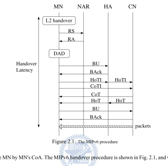
reach the MN by MN's CoA. The MIPv6 handover procedure is shown in Fig. 2.1, and we divide this procedure into following two stages.
Agent Discovery Stage
After a MN loses connectivity with the previous AP, it performs Layer 2 handover and then associates with a new AP. When a MN roams out of its home network, it performs Router Discovery [8] to obtain some information about its new access router (NAR). A MN may be assigned a new CoA in this stage. Without being assigned new CoA from the NAR, a MN forms a tentative CoA itself and performs DAD process to ensure this CoA is available.
Registration Stage
When the new CoA is available, the MN initiates a Home Registration by sending a Binding Update message, which includes MN's current CoA. This registration procedure is completed when the MN receives a Binding Acknowledgement message from the HA. Before a Correspon-dent Registration, the MN performs return routability procedure to ensure both paths between the MN and the CN, one via the HA and the other directly, are reachable. The MN initiates this procedure by sending the Home Test Init message via the HA to the CN and the Care-of Test Init message directly to the CN at the same time. Once the CN receives these messages, it sends Home Test and Care-of Test to the MN through the same paths as the request messages. Finally, the MN sends a BU to CN, and receives a BAck from the CN. The MIPv6 procedure is completed. From that time, the MN can communicate with other nodes by both home address and care-of address in the new network.
2.1.2
Fast Handovers for Mobile IPv6
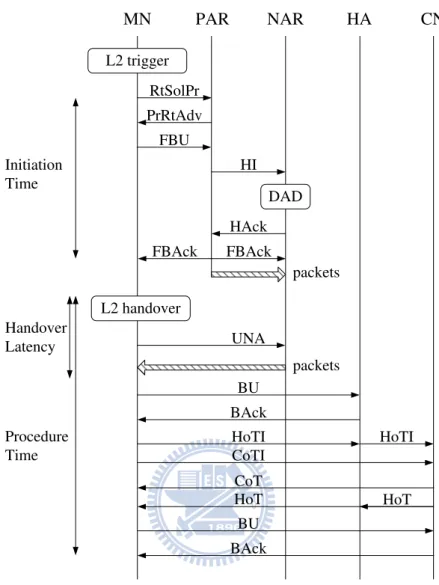
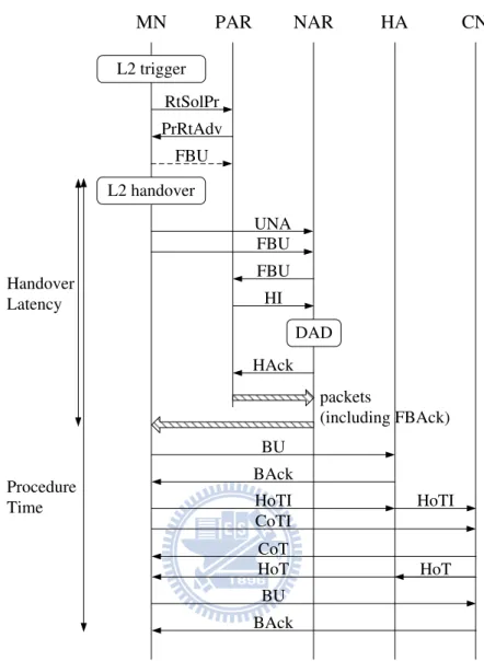
Since a MN is unable to send and receive packets during the period of time performing MIPv6 procedure, the Fast Handovers for Mobile IPv6 is an enhancement of the MIPv6 protocol. It shortens the period of time a MN losing connectivity during a handover. Two different modes, predictive and reactive, are proposed in this protocol, and a MN performs reactive fast handover only if it fails to perform predictive fast handover. When the FMIPv6 procedure performs in the predictive mode, its handover latency is shorter than performing the MIPv6 procedure; however, the handover latency in reactive mode is much longer than in its counterpart and leads to an increase in the average handover latency. The FMIPv6 predictive handover procedure is shown in Fig. 2.2, and the reactive one is shown in Fig. 2.3. We divide the procedure into following three stages.
L2 trigger L2 handover UNA MN PAR NAR HA CN HoTI CoTI HoTI CoT HoT BAck BU BAck BU RtSolPr PrRtAdv FBU HI HAck FBAck FBAck DAD packets packets Initiation Time Handover Latency Procedure Time HoT
Figure 2.2: The FMIPv6 procedure in predictive mode
Agent Discovery Stage
The FMIPv6 advances the Neighbor Discovery stage in the MIPv6 to the time before Layer 2 handover. When the MN discovers other available APs by link-specific methods, it sends an RtSolPr to its access router and the FMIPv6 procedure begins. Before the new CoA config-uration, the PrRtAdv is sent as response message, which includes information about possible NARs.
L2 trigger L2 handover UNA MN PAR NAR HA CN HoTI CoTI HoTI CoT HoT BAck BU BAck BU RtSolPr PrRtAdv FBU FBU DAD packets (including FBAck) Handover Latency Procedure Time FBU HI HAck HoT
Figure 2.3:The FMIPv6 procedure in reactive mode
Early Registration Stage
Once the PAR receives a Fast Binding Update, which includes MN's tentative CoA, from the MN, it sends a Handover Initiate message with the proposed CoA to the NAR. The NAR checks MN's new CoA for uniqueness and sends a Handover Acknowledgement to the PAR in response. After that, the previous CoA binds to the new CoA, and packets toward the MN are forwarded to the NAR for buffering. This stage is completed only in predictive fast handover, when the MN receives a Fast Binding Acknowledgement on the previous link.
Registration Stage
As soon as the MN establishes link connectivity with the NAR, it sends an Unsolicited Neighbor Advertisement to the NAR. In the predictive mode, the NAR starts forwarding packets in its buffer to the MN. In the reactive mode, the MN sends a FBU to the PAR following an UNA message, then receives a FBAck and buffering packets from the PAR.
The FMIPv6 protocol establishes a tunnel between the PAR and the NAR, and makes the MN receive packets on the new link before Home Registration and Correspondent Registration.
2.1.3
Enhanced Tentative and Early Binding Update
FMIPv6 with TEBU
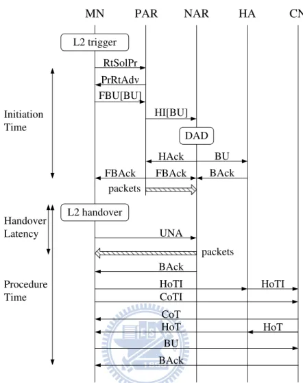
S. Ryu and Y. Mun [9][10] proposed a method, Tentative and Early Binding Update (TEBU), to complete the predictive FMIPv6 procedure earlier. It did not reduce the exchanging messages in the FMIPv6 protocol, but moving the BU to the HA prior to a L2 handover and reducing the messages in a new network. In this protocol, a new cache is implemented in the HA to save the tentative CoA and the current CoA at the same time.
After receiving a PrRtAdv, the MN sends a FBU message, which encapsulates a BU to its HA. MN's PAR sends a HI message to MN's NAR, and the NAR forwards the BU message encapsulated in the HI to MN's HA. The HA stores the tentative CoA in the BU message in its cache, and sends a BAck message to MN's NAR. Once the MN informs the NAR its arrival, the NAR forwards the BAck message to the MN. Therefore, the MN registers its NCoA to the HA prior to a L2 handover, and the handover procedure will end earlier. The message flow of the TEBU scheme is shown in Fig. 2.4.
L2 trigger L2 handover UNA MN PAR NAR HA CN RtSolPr PrRtAdv FBU[BU] HI[BU] HAck FBAck FBAck DAD packets packets Initiation Time Handover Latency Procedure Time BU BAck BU BAck BAck HoTI CoTI HoTI CoT HoT HoT
Figure 2.4: The FMIPv6 procedure with the TEBU scheme
FMIPv6 with eTEBU
The Enhanced Tentative and Early Binding Update (eTEBU) scheme is based on the TEBU scheme and performs part of the return routability procedure prior to the L2 handover. Therefore, the timing a MN can communicate with its CN directly is advanced, and the cost in triangle routing can be reduced. The message flow of the eTEBU scheme is shown in Fig. 2.5.
2.1.4
Discussion
The DAD procedure and Return Routability procedure are the bottlenecks of the discon-nection time in the Mobile IPv6. The predictive Fast Handovers for Mobile IPv6 resolves these
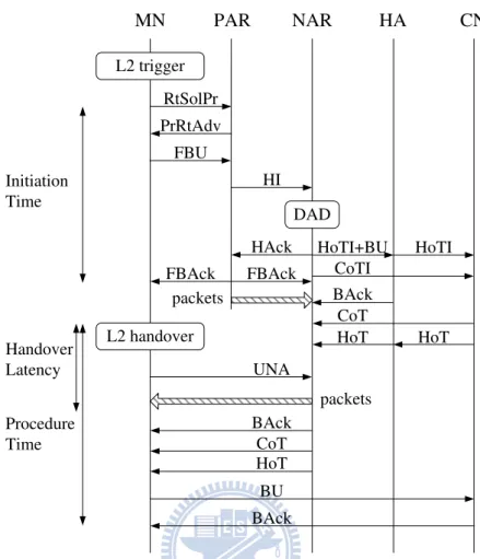
L2 trigger L2 handover UNA MN PAR NAR HA CN RtSolPr PrRtAdv FBU HI HAck FBAck FBAck DAD packets packets Initiation Time Handover Latency Procedure Time HoTI+BU CoTI HoTI CoT HoT BAck BU BAck BAck CoT HoT HoT
Figure 2.5: The FMIPv6 procedure with the eTEBU scheme
disadvantages by performing the DAD procedure in the old link, and transmitting buffered data packets before the Return Routability procedure. However, if the predictive Fast Handovers for Mobile IPv6 fails, the protocol will work in reactive mode and the DAD procedure increase the disconnection time. Therefore, both rising the successful predicting rate and reducing the DAD delay can improve the performances of all MIPv6-based protocols.
2.2
Advance Duplicate Address Detection
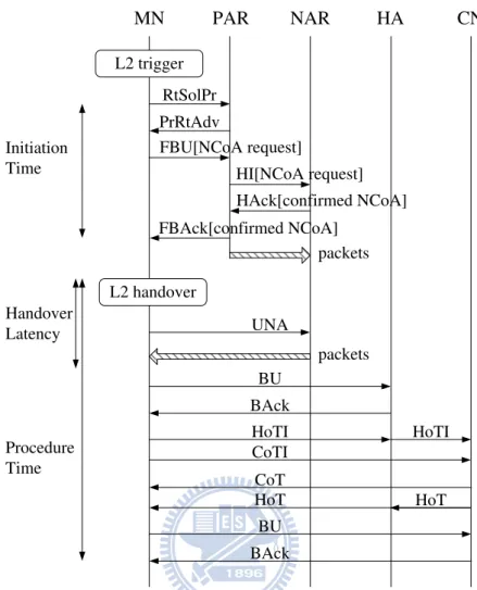
Advance Duplicate Address Detection provides a solution to improve the DAD delay. In this protocol, an AR manages an address pool, which stores the unique IPv6 addresses, and provides those addresses to a MN who has sent a request to the AR.
L2 trigger L2 handover UNA MN PAR NAR HA CN HoTI CoTI HoTI CoT HoT BAck BU BAck BU RtSolPr PrRtAdv FBU[NCoA request] HI[NCoA request] HAck[confirmed NCoA] FBAck[confirmed NCoA] packets packets Initiation Time Handover Latency Procedure Time HoT
Figure 2.6: The FMIPv6 procedure with the ADAD scheme
The AR generates some address and performs the DAD process on them; if an address is duplicate-free, the AR stores it in its Passive Proxy Cache. If a MN performs the DAD procedure on an address which was in the AR's cache, the AR has to remove the address from its cache. Then, in order to keep the amount of the unique address in its address pool a constant, the AR generates a new address and tests its uniqueness; if the new address is unique, the AR stores it. The FMIPv6 can be enhanced by the advance DAD, the enhaced protocol flow is shown in Fig. 2.6. After a L2 trigger [11] and Router Discovery stage, the MN sends a FBU with a new flag to the PAR and requests for a NCoA. The PAR sends a HI message with this flag to the NAR, the the NAR replies the PAR a HAck with a confirmed NCoA, which is selected from the NAR's address pool. Since the uniqueness of the NCoA is confirmed by the NAR, the MN can
Chapter 3
Enhanced Fast Handovers for Mobile IPv6
In our proposal, the enhanced FMIPv6 protocol increases the percentage of successful pre-dicting, which indicates a handover performing in predictive mode, and decreases the handover latency on average.
3.1
Components
The functions of the components in our protocol are specified as follows.
• Mobile Node
A MN is a mobile device in the wireless network environment. When a MN leaves its home network and enters a new network, it must register its current CoA, which is an address using out of MN's home network, with its HA. Also, a MN has to request its current AR for a NCoA. When a L2 trigger occurs, the MN should inform its PAR to redirect the traffic to its NAR.
• Access Router
An AR is a router which manages a subnet the MN connecting to. A PAR is MN's access router prior to its handover. A NAR is MN's access router subsequent to its handover [7]. When a MN requests for a NCoA used in neighbor network, the AR provides the MN a group of possible CoAs of its neighbor network. When a MN requests for a NCoA used in current network, the AR provides the MN a CoA of its network. The PAR redirects MN's packets to the NAR when a handover occurs, the NAR stores these packets in its
cache and forwards them to the arriving MN.
• Home Agent
A HA makes the MN can be reachable by others with its home address. When a MN is out of its home network, the HA receives packets to MN's home address, and forwards them to MN's current CoA. In a handover procedure, a HA proves MN's home address is reliable by forwarding a test message using MN's home address to the CN.
• Correspondent Node
A CN is a device which communicates with the MN. The CN has no idea if a handover occurs or not, therefore, it always sends the packets to MN's PCoA until the MN informs the CN of its NCoA.
3.2
Protocol Flow
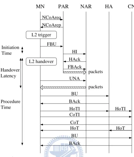
Our protocol is based on the FMIPv6, for this reason, there are two different mode in our eFMIPv6 protocol. The predictive mode is shown in Fig. 3.1, and the reactive mode is shown in Fig. 3.2. We propose two new messages in the eFMIPv6, which are NCoAreq/ NCoArep messages instead of RtSolPr/ PrRtAdv messages in the Router Discovery stage of the FMIPv6 protocol, and remove a FBAck message to a MN. A NCoArep message can work on two ways, one provides a MN a group of NCoAs, and the other assigns a MN a specific NCoA. When an AR works as a PAR, it sends NCoArep with NCoAs of its neighbor network. Otherwise an AR works as a NAR, and sends NCoArep with a NCoA of its home network. We will show the two usage of NCoArep message later. We also introduce a new scheme to make the NAR instead of the MN to determine whether the handover occurs in the reactive mode. This modification reduces the messages exchanged between a MN and its PAR before a L2 handover, and increases
L2 trigger L2 handover UNA MN PAR NAR HA CN HoTI CoTI HoTI CoT HoT BAck BU BAck BU NCoAreq NCoArep FBU HI HAck packets Initiation Time Handover Latency Procedure Time FBAck packets HoT
Figure 3.1: The enhanced FMIPv6 procedure in predictive mode
the rate of handover which occurs in predictive mode.
Once a MN attends a network, it sends the PAR a NCoAreq message to ask for NCoAs. The PAR sends the MN a NCoArep message which encapsulates some candidates CoAs from its neighbor address pool, and marks those CoAs are hold by the particular MN. Since the MN has obtained multiple unique CoAs, it chooses a suitable NCoA and sends a FBU message to the PAR immediately following a L2 trigger without Agent Discovery. To a MN, the initiation stage is finished after sending a FBU message, and it has no idea whether the tunnel between the PAR and the NAR is established.
On the other side, while receiving a FBU message, the PAR updates its neighbor address pool and marks those CoAs which are released by the MN available. Then the PAR sends a HI message to the NAR in order to request setting up the tunnel between the PAR and the NAR.
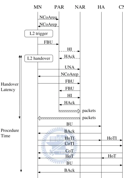
L2 trigger L2 handover UNA MN PAR NAR HA CN HoTI CoTI HoTI CoT HoT BAck BU BAck BU NCoAreq NCoArep FBU HI HAck packets Handover Latency Procedure Time packets FBU FBU HI HAck NCoArep HoT
Figure 3.2:The enhanced FMIPv6 procedure in reactive mode
Due to the uniqueness of a CoA has been confirmed before being provided to its neighbor AR, the NAR has no need to perform the DAD procedure after receiving a HI message. The NAR creates a path, which the PAR can forward the MN's packets from the MN's previous link to the new network, and sends relative information to the PAR in a HAck message. The PAR responses this message by a FBAck message and forwards packets to the NAR through this tunnel.
3.3
Operating Modes
In our protocol, the NAR takes the responsibility to determine whether this modified FMIPv6 protocol performs in predictive mode. When a NAR receives a UNA message from a MN, it checks its cache to verify that the tunnel between the PAR and the NAR exists. If the tunnel does not exist, it means that the handover procedure performs in reactive mode. We insert a NCoArep message between the UNA message and the FBU message, in order to assign the MN a particular NCoA in the reactive mode. By using an assigned NCoA, the MN avoids wasting a long time to perform the DAD procedure. Therefore, the handover latency in reactive mode of FMIPv6 reduces.
Chapter 4
Pool-based Address Provisioning Scheme
To reduce the DAD delay, we proposed a Pool-based Address Provisioning Scheme (PAPS) which based on the Advanced DAD (ADAD) technique[5]. This modification not only reduces the DAD performing time, but also moves the Agent Discovery stage prior to a L2 trigger in our eFMIPv6 protocol.
4.1
Address Management
We use the ADAD technique proposed by Y. Han and S. Hwang in [5] to configure ad-dresses, and modify the address pool and address provisioning method in our Pool-based Ad-dress Provisioning Scheme.
We design a special cache in each AR which stores the duplicate-free addresses. Each AR manages a home address pool and a neighbor address pool, which reserve some unique addresses in its home network and neighbor networks respectively. The design of address pools is introduced in next section. As we mentioned before, a PAR replies to a NCoAreq message with a group of NCoAs of its neighbor network, and a NAR replies to the same message with a unique NCoA in its network.
The address generation technique we used is the same as the ADAD, an AR generates some addresses and test the uniqueness of them. All of the unused addresses are stored in AR's home address pool. An AR keeps generating and testing duplicate-free addresses until the home address pool is full, and every AR provides addresses in its home address pool for its neighbor
ARs periodically. When an AR receives a duplicate-free address from its neighbor AR, it stores the address or updates the existing entry in its neighbor address pool. Each AR also updates it neighbor address pool once receiving a FBU message from a MN. We assume a MN has particular techniques to determine a proper NCoA from the provided candidates when receiving a L2 trigger.
4.2
Address Pool Design
Original Network Network A Network B Network C M1 M6 M5 M4 M2 M3
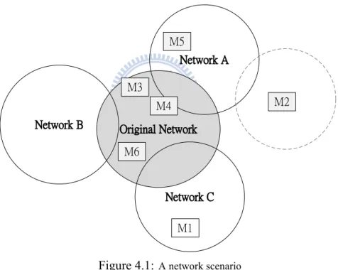
Figure 4.1: A network scenario
3ffe:3600:17:4:17:2dff:fe12:3456 3ffe:3600:17:4:20:7eff:fe13:1234 3ffe:3600:17:4:81:7eff:fe23:2a0b 3ffe:3600:17:4:81:3bff:fe23:3f1d 3ffe:3600:17:4:83:3dff:fe32:408d NA NB NB NC 3ffe:3600:17:4:15:7eff:fe13:27cd NA U
Home Address Pool
. . . . . .
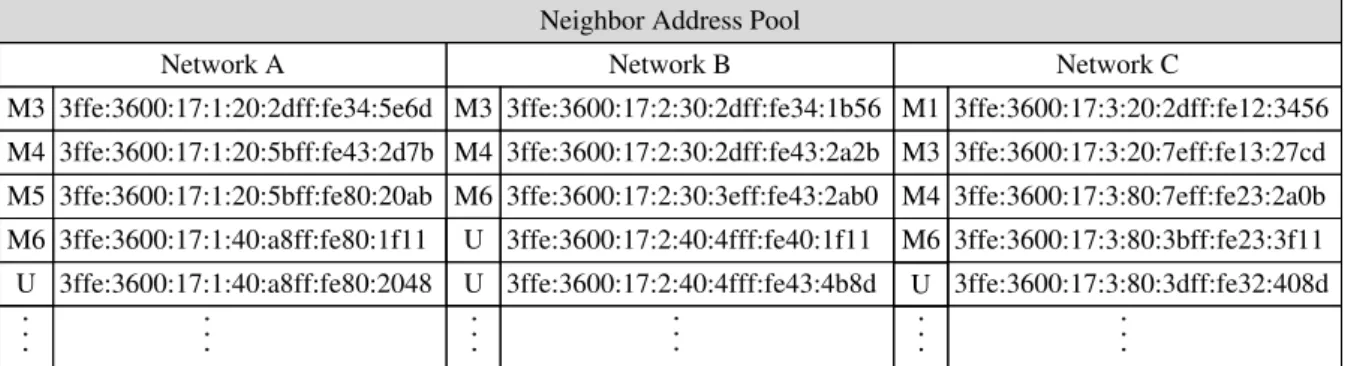
Neighbor Address Pool Network A 3ffe:3600:17:1:20:2dff:fe34:5e6d 3ffe:3600:17:1:20:5bff:fe43:2d7b 3ffe:3600:17:1:20:5bff:fe80:20ab 3ffe:3600:17:1:40:a8ff:fe80:1f11 3ffe:3600:17:1:40:a8ff:fe80:2048 M3 M4 M5 M6 Network B 3ffe:3600:17:2:30:2dff:fe34:1b56 3ffe:3600:17:2:30:2dff:fe43:2a2b 3ffe:3600:17:2:30:3eff:fe43:2ab0 3ffe:3600:17:2:40:4fff:fe40:1f11 3ffe:3600:17:2:40:4fff:fe43:4b8d M3 M4 M6 Network C 3ffe:3600:17:3:20:2dff:fe12:3456 3ffe:3600:17:3:20:7eff:fe13:27cd 3ffe:3600:17:3:80:7eff:fe23:2a0b 3ffe:3600:17:3:80:3bff:fe23:3f11 3ffe:3600:17:3:80:3dff:fe32:408d M1 M3 M4 M6 U . . . U U U . . . . . . . . . . . . . . .
Figure 4.3:The structure of neighbor address pool
Before introducing our design of the address pools, a network scenario is shown in Fig. 4.1. Networks A, B, and C are neighbors of the original network. There are 6 mobile nodes in this scenario; at the beginning, all of them were in the original network. Then, the mobile nodes M1, M2, and M5 roam out of the original network, the mobile node M1 goes to Network C, the mobile node M5 goes to Network A, and the mobile node M2 goes to another network which is not on the neighbor list of the original network.
An AR marks each home address pool entry with a neighbor network which keeps this address in its neighbor address pool. In Fig. 4.2, it shows the design of the home address pool in the original router. Some duplicate-free addresses in original network are assigned to neighbor networks, and some are not. For example, an entry marked as NA means the address in this entry is hold by Network A; and, an entry marked as U means that there is no neighbor network holds this address. Original network assigns the same quantity of unique addresses to each neighbor periodically; but neighbor networks have technology to ask original network for more addresses when they run out of avaliable addresses of original network.
An AR also marks each neighbor address pool entry with a MN which keeps this address. When a MN roams out, it only reserves the NCoA of its new network and the unused addresses are released. When receiving a FBU from a MN, the PAR clears all marks of this MN from its neighbor address pool except the address encapsulates in the FBU. The design of the
neigh-bor address pool is shown in Fig. 4.3. It noticeable that all the marks of M2 are clear, which means M2 has leaved the original network and its neighbor networks. Also, only one address in neighbor address pool is marked by M1, which indicates M1 roams to the neighbor of original network.
Chapter 5
Time Measurment
In this chapter, we analyze the handover time of the MIPv6, predictive FMIPv6, reactive FMIPv6, predictive FMIPv6 with eTEBU scheme, and the protocol we proposed. We define three evaluation factors and also use a simplified analysis model to assess different handover protocols.
5.1
Time Measurement Factors
Since each handover protocol starts the handover procedure at distinct time point, it is sub-jective to compare their handover delay by measuring the time period between the first handover message to the last one. Therefore, we define three factors to regulate the time interval during the handover process, and evaluate each handover protocol objectively.
We use the time point when a L2 handover begins to divide all handover procedures into two stages, the first is an Initiation Stage which ends before a L2 handover, and the other is a Procedure Stage which starts from a L2 handover. One of our evaluation factors reflects a time period in the Initiation Stage, and the remaining factors measures different time intervals in the Procedure Stage.
• Initiation Time
It is defined as the time interval between the moment when the MN sends the first mes-sage after receiving a L2 trigger and the moment when the MN receives or sends its last handover message before a L2 handover. We are interested in this factor, because the
initiation time is a key factor which decides the mode in the predictive FMIPv6-based protocol.
• Handover Latency
It is defined as the time interval between the moment when the MN starts a L2 handover and the moment when the MN receives its first data packet from its NAR in a new network. The application is aware of the packets delay due to the handover latency.
• Procedure Time
It is defined as the time interval between the moment when the MN starts a L2 handover and the moment when the MN receives a BAck from one of its CN. Although the third fac-tor overlaps the second facfac-tor, the procedure time measures the handover delay in different view. The MN cannot communicate with the CN directly until the end of the procedure time.
5.2
Evaluation Model
MN tmc CN thc tpn ts th IPv6 Network Home Network HA MN NAR PARTable 5.1: Notations
th The delay between the MN and its home network
ts The delay between the MN and any AR
tpn The delay between the PAR and the NAR
tmc The delay between the MN and the CN
thc The delay between the MN's home network and the CN
tL2 The interruption of the L2 handover
tDAD The time required for completing the DAD procedure
In the following analysis, we adopt the analysis model presented in [12][13] to evaluate the time cost of handover. We also assume a symmetric delay, where the delay time between two specified devices is a constant in a handover procedure. We also assume that processing time in each entity is negligible. The analysis model is shown in Fig. 5.1 and the notations we used are shown in Table 5.1.
5.3
Analysis
5.3.1
Mobile IPv6 Handover
In the MIPv6, the handover procedure begins when the MN starts the L2 handover; there-fore, it is not necessary to consider the initiation time in this protocol.
• Handover Latency
The handover begins with a L2 handover, which takes tL2. Then, the MN sends a router solicitation and receives a router advertisement from its NAR, which takes 2ts. After performing the DAD procedure which takes tDAD, the MN sends a BU to its HA and receives a BAck, which takes 2th. The return routability procedure starts when the MN sends the HoTI and CoTI to a CN at the same time, and ends when the MN receives both
the HoT and CoT; therefore, we have to consider the longest time in our measurement, which is the one via HA and takes 2th+2thc. After the MN sends a BU to a CN, it receives a BAck and its first data packet in the new subnet, which takes 2tmc. The handover latency in MIPv6 takes tL2+ tDAD+ 2ts+ 4th + 2thc+ 2tmc.
• Procedure Time
In the MIPv6, the procedure time is the same as the handover latency, which takes tL2+
tDAD+ 2ts+ 4th+ 2thc+ 2tmc.
5.3.2
Predictive Fast Handovers for Mobile IPv6
• Initiation Time
Following by a L2 trigger, the MN send a RtSolPr message to its PAR and receives a PrRtAdv message. This router discovery procedure takes 2ts. Subsequently, the MN sends a FBU message to its PAR, which takes ts. MN's PAR sends a HI message to MN's NAR, then MN's NAR performs the DAD procedure and sends a HAck message back, which takes 2tpn+ tDAD. After receiving a HAck, MN's PAR sends a FBAck message to both the MN and its NAR, which takes ts. The initiation time in the predictive FMIPv6 is
tDAD+ 2tpn+ 4ts.
• Handover Latency
After a L2 handover which takes tL2, the MN sends an UNA message to its NAR, which takes ts. Subsequently, the MN receives its first data packet in new network, which takes
ts. The handover latency in the predictive FMIPv6 is tL2+ 2ts.
• Procedure Time
the first data packet, the MN and its HA exchange the BU and BAck, which takes 2th. As we mentioned before, the return routability procedure takes 2th+ 2thc. Finally, the MN and one of its CN exchange the BU and BAck, which takes 2tmc. The procedure time in predictive FMIPv6 is tL2+ 2ts+ 4th+ 2thc+ 2tmc.
5.3.3
Reactive Fast Handovers for Mobile IPv6
When the MN performs the FMIPv6 handover in reactive mode, it means the predictive handover in the old link was failed. Therefore, we do not take the initiation time into account.
• Handover Latency
After a L2 handover, the MN sends a UNA and a FBU message to the NAR at the same time, which takes ts. Then, the NAR forwards the FBU message to MN's PAR, which takes
tpn. MN's PAR sends a HI message to MN's NAR, then MN's NAR performs the DAD procedure and sends a HAck message back, which takes 2tpn+ tDAD. The tunnel between the PAR and the NAR is established at this time, and the MN receives its first data packets after tpn+ ts. The handover latency in the reactive FMIPv6 is tL2+ tDAD+ 4tpn+ 2ts.
• Procedure Time
After the MN receives its first data packet in the new network, the remaining handover procedure in reactive FMIPv6 is the same as the predictive FMIPv6, which takes 4th + 2thc+ 2tmc. The procedure time in reactive FMIPv6 is tL2+ tDAD+ 4tpn+ 2ts+ 4th+ 2thc+ 2tmc.
5.3.4
Predictive Fast Handovers for Mobile IPv6 with eTEBU
• Initiation Time
The initiation time in the predictive FMIPv6 with eTEBU is the same as the predictive FMIPv6, which is tDAD+ 2tpn+ 4ts.
• Handover Latency
The handover latency in the predictive FMIPv6 with eTEBU is the same as the predictive FMIPv6, which is tL2+ 2ts.
• Procedure Time
As shown in Fig. 2.5, the NAR starts two tasks at the same time after performing a DAD procedure. In the first task, the NAR informs the MN the result of the DAD process and the initiation stage is over. In the other one, the NAR registers MN's NCoA with MN's HA and forwards the return routability messages to the CN, and takes max(2(th− ts), 2(th−
ts+ thc), 2(tmc− ts)). Since the second task is independent of the handover procedure among the MN and the ARs until the NAR is informed the arrival of the MN, the handover are performed in parallel during this period and we must measure the longer interval to calculate the procedure time.
It is hard to calculate the procedure time because the second task performing across the Ini-tiation Stage and Procedure Stage; therefore, we only consider the worst case and the best case here. The worst case occurs when a L2 handover immediately following a FBAck message, in other words, most of messages in the second task transmit in the new network. The procedure time in this case is max(2(th−ts), 2(th−ts+thc), 2(tmc−ts))−tpn+2tmc. The best case occurs when the second task finishes in the Initiation Stage, and the proce-dure time in this case is tL2+ ts+ 2tmc.
5.3.5
Predictive Fast Handovers for Mobile IPv6 with advance DAD
• Initiation Time
Advance DAD is performed instead of the original DAD procedure in FMIPv6, hence the DAD procedure time is eliminated. The initiation time in the predictive FMIPv6 with advance DAD is 2tpn+ 4ts.
• Handover Latency
The handover latency in the predictive FMIPv6 with advance DAD is the same as the predictive FMIPv6, which is tL2+ 2ts.
• Procedure Time
The procedure time in predictive FMIPv6 with advance DAD is the same as the predictive FMIPv6, which is tL2+ 2ts+ 4th+ 2thc+ 2tmc.
5.3.6
Proposed Handover Protocol in Predictive Mode
• Initiation Time
There is only a FBU message which sends by the MN in the Initiation Stage; hence the initiation time in our predictive handover protocol is ts.
• Handover Latency
There are two tasks following a FBU message, one is a handover initiation process be-tween the PAR and the NAR, the other is a L2 handover on the MN. Because these two process can be performed in parallel, the handover latency in our predictive handover protocol is max(tL2+ 2ts, 4tpn).
procedure in our predictive protocol is the same as the predictive FMIPv6, which takes 4th+ 2thc + 2tmc. Therefore, the procedure time in our predictive handover protocol is
max(tL2+ 2ts, 4tpn) + 2th+ 2thc+ 2tmc.
5.3.7
Proposed Handover Protocol in Reactive Mode
As we mentioned before, we do not care about the initiation time in a reactive mode, there-fore we only consider the handover latency and procedure time in this section.
• Handover Latency
A MN sends an UNA message to inform the NAR its arrival, which takes ts. When the NAR cannot find the corresponding entry of MN in its cache, it assigns this MN a NCoA by NCoArep, which takes ts. After receiving its NCoA, the MN sends a FBU message to its PAR via the NAR, which takes ts + tpn. MN's PAR sends a HI message to MN's NAR and receives the acknowledgement message HAck, which takes 2tpn. The tunnel between the PAR and the NAR is established, and the MN receives its first data packets after tpn+ ts. The handover latency in our reactive handover protocol is tL2+ 4tpn+ 4ts.
• Procedure Time
After the MN receives its first data packet in the new network, the remaining handover procedure in our reactive protocol is the same as the predictive FMIPv6, which takes 4th+ 2thc+ 2tmc. The procedure time in our reactive handover protocol is tL2+ 4tpn+ 4ts+ 4th+ 2thc+ 2tmc.
Table 5.2: The result of time measurement in each protocol
- Initiation Time Handover Latency Procedure Time
MIPv6 N/A tL2 + tDAD + 2ts +
4th+ 2thc+ 2tmc
tL2+tDAD+2ts+4th+2thc+ 2tmc
FMIPv6 (predictive) tDAD+ 2tpn+ 4ts
tL2+ 2ts tL2+ 2ts+ 4th+ 2thc+ 2tmc
FMIPv6 (reactive) N/A tL2+ tDAD+ 4tpn+
2ts
tL2 + tDAD + 4tpn + 2ts + 4th+ 2thc+ 2tmc
FMIPv6 with eTEBU (best case)
tDAD+ 2tpn+ 4ts
tL2+ 2ts tL2+ ts+ 2tmc FMIPv6 with eTEBU
(worst case)
tDAD+ 2tpn+ 4ts
tL2+ 2ts max(2(th− ts), 2(th− ts+
thc), 2(tmc−ts))−tpn+2tmc FMIPv6 with ADAD 2tpn+ 4ts tL2+ 2ts tL2+ 2ts+ 4th+ 2thc+ 2tmc eFMIPv6 (predictive) ts max(tL2+ 2ts, 4tpn) max(tL2+ 2ts, 4tpn) + 2th+
2thc+ 2tmc
eFMIPv6 (reactive) N/A tL2+ 4tpn+ 4ts tL2+4tpn+4ts+4th+2thc+ 2tmc
Chapter 6
Comparisons
6.1
Time Cost
In this section, we calculate the results of our analysis in Chapter 5, which using the parame-ters in Table 5.1 to represent all the Time Measurement Factors in each protocol. The parameparame-ters used in the following analysis are set to the typical values found in [13], [14], and [15]. They are th = 112 ms, ts = 11 ms, tpn = 5 ms, tmc = 124 ms, thc = 114 ms, tL2 = 50 ms, and
tDAD = 500 ms.
6.1.1
Initiation Time
The factor "Initiation Time" is used to evaluate when a FMIPv6-based protocol will work in predictive mode. We only compare three FMIPv6-based protocols here, because the FMIPv6 with eTEBU scheme has the same Initiation Time as original FMIPv6 protocol.
Firstly, we define the time points when a L2 trigger and a L2 handover occur in a wireless network. We look up the receive sensitivity of the network interface card from D-Link (DWL-G630), which is shown in Table 6.1, and define a L2 trigger occurs when the signal strength is
−90 dBm in 802.11b, or −87 dBm in 802.11g. Also, we define a L2 handover occurs when the
signal strength is−92 dBm in 802.11b or -89 dBm in 802.11g.
Table 6.1: Receive sensitivity of NIC DWL-G630 802.11b 802.11g 11 Mbps (PBCC) −85 dBm 54 Mbps (OFDM) −71 dBm 11 Mbps (CCK) −84 dBm 48 Mbps (OFDM) −72 dBm 5.5 Mbps (CCK) −87 dBm 36 Mbps (OFDM) −77 dBm 2 Mbps (QPSK) −90 dBm 24 Mbps (OFDM) −80 dBm 1 Mbps (QPSK) −92 dBm 12 Mbps (OFDM) −86 dBm - - 9 Mbps (OFDM) −87 dBm - - 6 Mbps (OFDM) −89 dBm
typically @PER < 8% packet size 1024
Table 6.2: Distance between a MN and its access point
802.11b 802.11g
RSSI distance RSSI distance
−90 dBm 72.05 m −87 dBm 58.44 m
−92 dBm 82.84 m −89 dBm 67.19 m Moving distance between a L2 trigger and a L2 handover
10.79 m 8.75 m
Table 6.3: MN's maximum moving speed to stay in predictive mode Protocol Initiation Time Max. Speed in 802.11b Max. Speed in 802.11g Example
FMIPv6 554 ms 7.0 km/hr 5.7 km/hr jogging speed
FMIPv6 with ADAD 54 ms 71.9 km/hr 58.3 km/hr driving speed
handover with referring to [16], which provides parameters using in the Path Loss Model. This model calculates the distance between the MN and the connected access point through radio signal strength (RSSI). The formula we use is distance =(10(RSSI+58.5)/(−33)). As a result, a MN's minimum moving distance between a L2 trigger and L2 handover is 10.79 m in 802.11b, or 8.75 m in 802.11g. The specific results are shown in Table 6.2.
We can ensure the FMIPv6-based protocols will work in the predictive mode, if its Initiation Time is shorter than its travelling time through the minimum moving distance. Therefore, we calculate a MN's maximum moving speed in the predictive mode using the expression shown in Table 5.2 and parameters defined at the beginning of this section, and the result is shown in Table 6.3. The FMIPv6 protocol cannot perform in predictive mode when its moving speed is higher than 7.0 km/hr; it means users may experience an interruption on their internet service while they are jogging. The bearable moving speed of FMIPv6 with advance DAD is 10 times higher than the original one, and users will not feel the handover when they use transportation in a city. The eFMIPv6 with PAPS is almost 5 times better than the FMIPv6 with advance DAD and the acceptable moving speed is up to 353.1 km/hr; therefore, users will not experience the handover even when they travel by the high speed railway.
6.1.2
Handover Latency
The "Handover Latency" evaluates the application-aware interruption during a handover. Since all of the FMIPv6-based protocol has the same Handover Latency in predictive mode, we only compare the Handover Latency of MIPv6, predictive FMIPv6, reactive FMIPv6, and the reactive mode in eFMIPv6.
We change the distance between a MN and its home network to evaluate the Handover Latency during a handover. The expression and parameters we use to calculate are shown in
0 200 400 600 800 1000 1200 1400 1600 1800 2 0 3 0 4 0 5 0 6 0 7 0 8 0 9 0 1 0 0 1 1 0 1 2 0 1 3 0 1 4 0 1 5 0 H a n d o v e r L a te n c y ( m s )
Delay between MN and Home Network (ms) MIPv6
FMIPv6 (reactive) eFMIPv6 (reactive) FMIPv6-based protocols (predictive)
Figure 6.1: Handover latency
0 50 100 150 200 250 300 1 0.96 0.92 0.88 0.84 0.8 0.76 0.72 0.68 0.64 0.6 A v e ra g e H a n d o v e r L a te n c y (m s )
Successful Prediction Rate
FMIPv6 eFMIPv6
Figure 6.2:Average handover latency
Table 5.2 and defined at the beginning of this section, and the result is shown in Fig. 6.1. In Fig. 6.1, it noticeable that only the Handover Latency of MIPv6 is dependent on the delay between a MN and its home network, the reason is a MN cannot receive new packets in a new network before updating its address in its HA. All of the FMIPv6-based protocols are independent of the distance between a MN and its HA, because packets are buffered in the NAR
and a MN can receive those buffered packets without sending binding update to its HA.
Even if in the reactive mode, eFMIPv6 performs almost as well as the predictive FMIPv6. The Handover Latency of eFMIPv6 is nearly the same in both predictive and reactive modes; it means users will not feel punishment interruption when a prediction before L2 handover fails. Fig. 6.2 shows the average Handover Latency versus the successful prediction rate. When the percentage of successful prediction falls, the Handover Latency increases slightly in eFMIPv6. By the time the successful prediction rate decreases to 0.6, the Handover Latency in FMIPv6 is almost 300 ms, which is three times over the Handover Latency in eFMIPv6.
Since the Handover Latency in eFMIPv6 is under 114 ms, it satisfies the End-user Perfor-mance Expectations of videophone and conversational voice [17], which prefer one-way delay less than 150 ms.
6.1.3
Procedure Time
The "Procedure Time" reflects the time period when data packets transmitting through tri-angular routing. Unnecessary network resources are occupied due to tritri-angular routing, which sends packets to a proxy system before sending to the intended destination. In the MIPv6-based handover procedure, the packets communicating between a MN and its CN send to MN's HA before sending to the destination, it not only leads to packets delay but also increases the net-work loading. Therefore, we compare the "Procedure Time" in various protocols to evaluate the network loading during a handover. Since the predictive FMIPv6, FMIPv6 with advance DAD have the same message flow in the Procedure Stage, we use predictive FMIPv6 to represent both protocols. In the following comparison, we change the delay time between the MN and its home network to calculate the "Procedure Time" among four protocols in different modes.
200 400 600 800 1000 1200 1400 1600 1800 2 0 3 0 4 0 5 0 6 0 7 0 8 0 9 0 1 0 0 1 1 0 1 2 0 1 3 0 1 4 0 1 5 0 P ro c e d u re T im e ( m s )
Delay between MN and Home Network (ms)
FMIPv6 (reactive) MIPv6
eFMIPv6 (reactive) FMIPv6 (predictive) eFMIPv6 (predictive) FMIPv6 with eTEBU (worst case)
FMIPv6 with eTEBU (best case)
Figure 6.3: Procedure time
and the MIPv6. Since these three protocols do not process the handover in advance before their roaming, they take longer Procedure Time than other predictive protocols. As shown in Fig. 6.3, the Procedure Time of the reactive protocol we proposed takes the shortest time, which is 400 ms shorter than the reactive FMIPv6 and the MIPv6 protocols.
Subsequently, we compare the Procedure Time of the remaining protocols which work in predictive mode. All of the predictive FMIPv6-based protocols start their handover procedure in the old link, and they take shorter Procedure Time. It is noticeable that even in the worst case the Procedure Time of the predictive FMIPv6 with eTEBU is shorter than other predictive protocols; the reason is that this scheme transmits some handover messages in parallel.
Fig. 6.4 shows the average Procedure Time versus the successful prediction rate. It is ap-parent that the Procedure Time of FMIPv6 is longer than 1000 ms regardless of the successful prediction rate, and the other protocols perform better than FMIPv6. Although eFMIPv6
per-200 400 600 800 1000 1200 1400 1 0 .9 6 0 .9 2 0 .8 8 0 .8 4 0 .8 0 .7 6 0 .7 2 0 .6 8 0 .6 4 0 .6 0 .5 6 0 .5 2 0 .4 8 A v e ra g e P ro c e d u re T ime ( ms )
Successful Prediciton Rate
FMIPv6
FMIPv6 with eTEBU (worst case)
eFMIPv6
FMIPv6 with eTEBU (best case)
Figure 6.4:Average procedure time
forms the second in the predictive mode, its performance in the reactive mode makes up for the average performance. Since eFMIPv6 not only improves the predictive FMIPv6 handover procedure but also the reactive one, when the percentage of successful prediction falls, there is only a slight increase in the Procedure Time. When the successful prediction rate is under 0.8, the Procedure Time of eFMIPv6 is shorter than the time of the worst case in eTEBU scheme, which is 825 ms. And the performance in eFMIPv6 exceeds the best case in eTEBU scheme when the successful prediction rate decreases to 0.51, which takes 902 ms in Procedure Stage.
6.2
Storage Cost
In this section, we examine the storage cost in various FMIPv6-based protocols. Firstly, we compare the additional cache size in the hardware among eTEBU, advance DAD, and eFMIPv6. Subsequently, we calculate the necessary buffer size in an AR, which supports video conver-sation services. To make our evaluation close to reality, we look up the specification of the wireless router from 3Com (WL-553). The maximum wireless users can be supported by this router is 64, and we apply this information to our evaluation.
6.2.1
Additional Cost on Address Pool
In order to improve the performance, some FMIPv6-based protocols use extra cache in their design, and so does eFMIPv6. Comparing with the original FMIPv6, we calculate the additional storage cost in FMIPv6-based protocols in this subsection, and this information may be helpful to choose a suitable FMIPv6-based protocol under different network conditions.
At first, we assume there is only one mobile node in each network to simplify the cal-culation. Then, we analyze the additional storage space in the hardware of each protocol. In this analysis, we also assume the neighbor address pool stores addresses from three neighbor networks in eFMIPv6. Table 6.4 shows the comparison of extra storage size among FMIPv6, FMIPv6 with eTEBU, FMIPv6 with advance DAD, and eFMIPv6. Since the length of IPv6 address is 16 Bytes, a MN in FMIPv6 with advance DAD needs 16 Bytes to store the assigned NCoA, and a MN in eFMIPv6 needs 48 Bytes to store three possible NCoAs from neighbor net-works. Although the storage space in eFMIPv6 is much more than others, it occupies less space in today's mobile device. The FMIPv6 with eTEBU is the only protocol which needs additional storage space in a HA. We know well about the additional storage cost in a HA, because a HA only serves MNs from its network.
Since an AR may act as a PAR and a NAR at the same time, we focus on the storage cost in an AR, and calculate the cache size at the maximum MN capacity in a network. When the
Table 6.4: Additional storage cost to serve a MN
Protocol MN AR HA
FMIPv6 N/A N/A N/A
FMIPv6 with eTEBU N/A N/A 16 Bytes
FMIPv6 wirth andvance DAD 16 Bytes 16 Bytes N/A
number of MNs is up to 64, the additional storage cost of eFMIPv6 is only 4.5 kB. Therefore, we have no need to worry about the storage cost of address pools.
6.2.2
Buffer Size Needed in AR
Figure 6.5:The buffer size during a handover latency period
In order to decrease the Handover Latency of the MIPv6, a cache is built in each AR to buffer data packets for a MN in FMIPv6. In this subsection, we calculate the least buffer size in an AR to support a handover during the video conversation. We have analyzed the Handover Latency, and the period of Handover Latency has key effect on the packets buffer size. Since all the FMIPv6-based protocol has the same Handover Latency in predictive mode, we only compare predictive FMIPv6, reactive FMIPv6, and eFMIPv6 in reactive mode. The parameters used in the following calculation are set to the average experiment result measured by [18].
In [18], the authors measure the average packet size in video conversation application. They use the software, Gnomemeeting, which uses Real-Time Transport Protocol (RTP), and sent the audio and video packets separately. Average video packet bandwidth is 950 Bytes/ms and average audio packet bandwidth is 70 Bytes/ms. We calculate the necessary buffer space in an
Figure 6.6:The average buffer size during a handover latency period
AR for a video conversation during a FMIPv6 handover, and plot the result versus the number of MNs in Fig. 6.5.
We can find the essential storage space in an AR working in reactive FMIPv6 increases gradually when the amount of MNs rising. When we have 64 MNs in a network, it needs 307 MB buffer space in reactive FMIP, but only needs 59 MB in predictive FMIPv6 and our reactive protocol. However, the FMIPv6 is nearly impossible to operate in reactive mode all the time, and the result shown in Fig. 6.5 is subjective. We calculate the average least buffer size with different successful prediction rate, and the result is shown in Fig. 6.6. When the successful prediction rate decrease from 1 to 0.7, there is only a slight increase in average essential buffer size for video conversation in eFMIPv6, but there is threefold increase in FMIPv6. When the successful prediction rate is 0.85, eFMIPv6 needs 41 MB to buffer packets for 64 mobile nodes, while FMIPv6 needs 78 MB to buffer packets for 64 mobile nodes.
Chapter 7
Conclusion
Nowadays, mobility management is a key issue in wireless network and we have various MIPv6-based protocols. However, we do not have an evaluation standard to compare their performance objectively. Since the handover time is a main feature in MIPv6-based protocols, in this thesis, we establish some measurement factors to evaluate the handover delay of different MIPv6-based protocols. We also propose a protocol which reduces the handover delay and guarantee the quality of service in real-time applications.
The successful prediction rate has a major effect on the disruption time during a FMIPv6-based handover. There are two key reasons lead to failed prediction, one is the unexpected moving path of mobile devices, and the other is the high moving speed of mobile devices. Al-though we cannot control the moving path of a MN, we allocate the NCoA in advance and modify the message flow and component functions of FMIPv6 to eliminate the effect of a MN's moving speed. In our protocol, the bearable moving speed of a MN increases to 286.4 km/hr, which is high enough to adjust almost every situation in our daily life.
We also propose an address provisioning scheme to optimize the average disruption time during a handover. We assign a unique address to each MN and remove the DAD procedure from a handover process; these changes reduce the interruption time in both predictive and reactive handovers but rise the load of each access router. Our protocol makes the average disruption time in a network services less than 150 ms, which guarantees the quality of service in a video conversation.
when the successful prediction rate is high; however, when the percentage of successful predic-tion falls, the increase of average handover completing time in our protocol is slighter than other protocols. Therefore, even if the successful prediction rate falls to 0.51, our protocol can keep the average handover completing time 900 ms while others cannot.
So far, we assume the mobile device has a technique to determine the best network after a L2 trigger, and we hope we can implement this technique in the future.
References
[1] C. Perkins, ''IP Mobility Support for IPv4,'' RFC 3344 (Proposed Standard), Aug. 2002, updated by RFC 4721. [Online]. Available: http://www.ietf.org/rfc/rfc3344.txt
[2] C. Perkins, P. Calhoun, and J. Bharatia, ''Mobile IPv4 Challenge/Response Extensions (Revised),'' RFC 4721 (Proposed Standard), Jan. 2007. [Online]. Available: http: //www.ietf.org/rfc/rfc4721.txt
[3] S. Thomson, T. Narten, and T. Jinmei, ''IPv6 Stateless Address Autoconfiguration,'' RFC 4862 (Draft Standard), Sep. 2007. [Online]. Available: http://www.ietf.org/rfc/rfc4862.txt
[4] D. Johnson, C. Perkins, and J. Arkko, ''Mobility Support in IPv6,'' RFC 3775 (Proposed Standard), Jun. 2004. [Online]. Available: http://www.ietf.org/rfc/rfc3775.txt
[5] Y. Han and S. Hwang, ''Care-of address provisioning for efficient ipv6 mobility support,''
Computer Communications, vol. 29, no. 9, p. 1422, 2006.
[6] H. Soliman, C. Castelluccia, K. ElMalki, and L. Bellier, ''Hierarchical Mobile IPv6 (HMIPv6) Mobility Management,'' RFC 5380 (Proposed Standard), Oct. 2008. [Online]. Available: http://www.ietf.org/rfc/rfc5380.txt
[7] R. Koodli, ''Mobile IPv6 Fast Handovers,'' RFC 5568 (Proposed Standard), Internet Engineering Task Force, Jul. 2009. [Online]. Available: http://www.ietf.org/rfc/rfc5568. txt
[8] T. Narten, E. Nordmark, W. Simpson, and H. Soliman, ''Neighbor Discovery for IP version 6 (IPv6),'' RFC 4861 (Draft Standard), Sep. 2007. [Online]. Available: http://www.ietf.org/rfc/rfc4861.txt
[9] S. Ryu and Y. Mun, ''The Tentative and Early Binding Update for Mobile IPv6 Fast Han-dover,'' Mobile Ad-Hoc And Sensor Networks, Proceedings, vol. 3794, p. 825, 2005.
[10] ---, ''A scheme to enhance tebu scheme of fast handovers for mobile ipv6,'' Embedded
Software and Systems, Proceedings, vol. 4523, p. 773, 2007.
[11] F. Teraoka, K. Gogo, K. Mitsuya, R. Shibui, and K. Mitani, ''Unified Layer 2 (L2) Abstractions for Layer 3 (L3)-Driven Fast Handover,'' RFC 5184 (Experimental), Internet Engineering Task Force, May 2008. [Online]. Available: http://www.ietf.org/rfc/rfc5184. txt
[12] T. Kwon, M. Gerla, and S. Das, ''Mobility management for voip service: Mobile ip vs. sip,'' IEEE Wireless Communications, vol. 9, no. 5, p. 66, 2002.
[13] H. Fathi, S. Chakraborty, and R. Prasad, ''Optimization of Mobile IPv6-Based Handovers to Support VoIP Services in Wireless Heterogeneous Networks,'' IEEE Transactions On
Vehicular Technology, vol. 56, no. 1, p. 260, 2007.
[14] C. Makaya and S. Pierre, ''An analytical framework for performance evaluation of IPv6-based mobility management protocols,'' IEEE Transactions on Wireless Communications, vol. 7, no. 3, p. 972, 2008.
[15] W. K. Lai and J. C. Chiu, ''Improving handoff performance in wireless overlay networks by switching between two-layer ipv6 and one-layer ipv6 addressing,'' IEEE Journal on
Selected Areas in Communications, vol. 23, no. 11, p. 2129, 2005.
[16] S. Lee, K. Nam, and K. Kim, ''The Location-based Services in Local Area using Wireless LAN,'' GML (Geography Mark-up Language) Days, 2004.
[18] J. Montavont, E. Ivov, and T. Noel, ''Analysis of Mobile IPv6 Handover Optimizations and Their Impact on Real-Time Communication,'' Proceedings of the IEEE Conference on