國立交通大學
電子工程學系 電子研究所
碩士論文
考慮差分對長度匹配的同時跳脫繞線
Simultaneous Escape Routing Considering Length
Matching of Differential Pairs
研究生:李彥融
指導教授:陳宏明教授、郭建男教授
考慮差分對長度匹配的同時跳脫繞線
Simultaneous Escape Routing Considering Length Matching of
Differential Pairs
研究生: 李彥融
Student: Yen-Jung Lee指導教授: 陳宏明教授
Advisor: Prof. Hung-Ming Chen郭建男教授
Prof. Chien-Nan Kuo國立交通大學
電子工程學系 電子研究所
碩士論文
A Thesis
Submitted to Department of Electronics Engineering and Institute of Electronics
College of Electrical and Computer Engineering National Chiao Tung University
In partial Fulfillment of the Requirements for the Degree of
Master of Science In
Electronics Engineering
August 2012
Hsinchu, Taiwan, Republic of China
i
考慮差分對長度匹配的同時跳脫繞線
學生: 李彥融 指導教授: 陳宏明教授、郭建男教授
國立交通大學 電子工程學系 電子研究所 碩士班
摘 要
跳脫繞線問題在數位印刷電路板的設計上扮演著重要的角色,且被廣泛的研究。不論 在工業界或學術論文上,數位印刷電路板上的同時跳脫繞線與差分對跳脫繞線等問題 已經有所進展,然而,考慮差分對長度匹配的同時跳脫繞線仍然是個待解決的問題。 本文中,我們基於 B-escape [1]繞線演算法與最小成本中點[2]的概念,實現了考慮 差分對長度匹配的同時跳脫繞線。實驗結果顯示我們的做法能比原本的 B-escape 演算 法在較少的時間內,有效且快速的達成差分對的同時跳脫繞線並做到長度匹配,藉此 減少電路中的差分對延遲差。ii
Simultaneous Escape Routing Considering Length Matching of
Differential Pairs
Student: Yen-Jung Lee Advisor: Prof. Hung-Ming Chen, Prof. Chien-Nan Kuo
Department of Electronics Engineering Institute of Electronics
National Chiao Tung University
ABSTRACT
In PCB(printed circuit board) design, the escape routing problem is considered an important part and has been widely studied in literature. There are industrial tools and some studies that work on simultaneous escape routing and escape routing of differentials pairs on dense circuit boards, however, to route differential pairs simultaneously considering length-matching is still an on-going research problem. In this thesis, based on the B-escape
routing algorithm [1] and the idea of min-cost median point used in differential pair
length-matching strategy [2], we have implemented a work that achieves simultaneous escape routing considering length matching of differential pairs. Experimental results show that our approach can efficiently and effectively obtain length-matching of differential pairs on simultaneous escape routing to reduce differential-pair skews with less running time than original B-escape router.
iii
誌 謝
感謝陳宏明老師的指導,指引我研究的方向,在我面臨難關時依然
給我鼓勵,讓我有堅持下去的力量。
感謝敬雨在研究過程中給予的協助,看似很大的問題,透過討論,
變得不那麼艱難,沒有你,我的研究可能還在空轉。
感謝 VDA LAB 的所有成員,你們爽朗的笑聲、親切的關心,都是我
debug 苦悶日子中的潤滑劑。
最後要感謝的事一直在背後默默支持我的家人與朋友們,謝謝你們
陪我聊天、分享心事,沒有你們我無法來到今日。
要感謝的人太多了,就謝天吧!
彥融的成就歸功於你們
iv
Contents
ABSTRACT(CHINESE) ... i ABSTRACT ... ii ACKNOWLEDGEMENTS ... iii List of Tables ... viList of Figures ... vii
Chapter 1. Introduction ... 1
1.1 Motivation and Contributions ... 1
1.2 Organization of This Thesis ... 4
Chapter 2. Problem Formulation ... 5
Chapter 3. Basic Ideas about B-escape and Our Implementation ... 6
3.1 Overview ... 6
3.1.1 Introduction to Simultaneous 2-Component Escape Routing ... 6
3.1.2 Previous Works ... 6
3.2 Boundary Routing ... 7
3.3 Dynamic Net Ordering ... 10
Chapter 4. Length Matching Method ... 13
4.1 Overview ... 13
4.1.1 Differential pair routing constraints ... 13
4.1.2 Previous Works ... 13
4.2 Min-Cost Median Point Finding ... 14
4.3 Shortest Pin-to-Pin Path through Median Point Enumerating ... 16
4.4 Median-Point-to-Boundary Path Determination Considering Net Ordering ... 17
v
Chapter 6. Conclusions ... 25 Bibliography ... 26
vi
List of Tables
TABLE I DESCRIPTION OF SIX ROUTING MODES IN B-ESCAPE ... 9 TABLE II BENCHMARK INFORMATION AND EXPERIMENTAL RESULTS . 23
vii
List of Figures
Fig 1 Simultaneous escape routing [1] ... 1
Fig 2 A differential pair routing result of B-escape... 3
Fig 3 Grid structure with switch boxes of B-escape ... 7
Fig 4 3-side escape routing ... 8
Fig 5 Six routing modes in B-escape [1] ... 10
Fig 6 Cost function ... 11
Fig 7 Backtrack and reorder ... 12
Fig 8 Differential pair routing solutions... 13
Fig 9 Differential pair routing method used in B-escape [1] ... 14
Fig 10 Possible min-cost median points ... 15
Fig 11 Transform from single line tile route to 2-line parallel route ... 15
Fig 12 Possible routing paths and possible crossing ... 16
Fig 13 2 pin-to-pin paths through the same median point ... 17
Fig 14 Wrong ordering of differential pairs in two components ... 18
Fig 15 Routing direction “up” in the 2nd component ... 19
Fig 16 No proper routing direction for the 2nd component ... 19
Fig 17 Route the right component first ... 20
Fig 18 Differential Pair Routing Considering Length Matching Algorithm ... 21
Fig 19 Routing result of case 3 obtained by our work ... 23
1
Chapter 1. Introduction
1.1 Motivation and Contributions
The problem of Printed circuit board (PCB) routing is to determine wiring connections between components on the printed circuit board. As the scale of modern electronic systems increases rapidly, the design of printed circuit boards (PCB) becomes more and more complex. Nowadays, a dense PCB contains tens of thousands of pins. The complexity of PCB routing makes it a time consuming job in industry. Without computer aids, it may take several weeks or even months for engineers to manually route a PCB with such a great number of pins. In this circumstance, good design automation for PCB routing can help reduce human efforts and design period.
In this thesis, we focus on the problem called escape routing, a key problem in PCB routing. Escape routing means the pins are “escaping” from the components, routing all terminal pins inside components on PCB to the component boundaries. Fig 1 shows that pins connecting two components are escaped to their respective component boundaries. (The inter-component connections are shown in dotted lines and their detailed routing paths will be determined in a subsequent detailed routing phase.)
2
The escape routing problem can be classified into ordered escape routing and unordered escape routing. The escaped wires around the grid boundary of the ordered escape routing are required to follow some ordering constraints while those of the unordered escape routing are not. In addition, ordered escape routing can be classified into single-component escape routing problem and simultaneous 2-component escape routing problem. In this thesis, we focus on simultaneous 2-component escape routing problem.
Differential-pair routing [2] is widely used in high-speed PCB design. Its high noise immunity, electromagnetic interference reduction, and ground bounce insensitivity makes it a better choice to transmit high-speed signal on a PCB. In each differential pair, one signal is transmitted by two complementary signals. These two signals are required to be transmitted in close proximity along a routing channel. Once the signal wires are routed close to each other, the noises on the channel can be simultaneously absorbed by the two signals.
Aside from routing proximity, experimental results [2] show that the length-matching differential pair obtains a smaller differential-pair skew than the non-length-matching one does. Nowadays, existing escape routing algorithms for simultaneous 2-component escape routing problem can handle differential pair routing problem [1]. However, it cannot guarantee that the two nets (from one pin to the grid boundary) of a differential pair are length matched. To further achieve length matching after the existing router, extra routing resource and manually rerouting is required. Since a smaller differential-pair skew is one major factor to achieve better performance of differential pairs, we try to make two nets have similar wire lengths in this work.
As for routing differential pairs, Yan et al. [4] and Li et al. [2] aim at the escape routing of differential pairs, while only [2] solves the length matching problem of differential pairs. Both of them focus on routing differential pairs on unordered
3
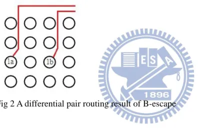
single-component escape routing. As for 2-component simultaneous ordered escape routing, B-escape [1] is an algorithm with the best routability among recent researches. B-escape accomplishes differential pair routing, however, length matching of differential pairs is not taken into consideration. In addition, in the differential pair routing result of B-escape, once the two pins in the same differential pair in the same component are in different columns, the routing path of the differential pairs inside the same component may split. This could lead to worse differential-pair skew. As shown in Fig 2, 1a and 1b are two pins of a differential pair in one component. Therefore, simultaneous 2-component escape routing considering length matching of differential pairs is still a problem to be solved.
Fig 2 A differential pair routing result of B-escape
Since industrial tools and previous works cannot solve the escape routing problem of differential pairs considering length matching, we propose an approach to solve the problem automatically. Our router is based on B-escape and can do net by net routing and differential pair routing at the same time. The differential pair length matching method is based on the concept of min-cost median point [2]. The wire lengths from the median point to the two pins of the differential pair are equal and shortest, satisfying length matching of differential pairs.
When it comes to route differential pairs, our length matching approach includes two stages. First, we find a suitable min-cost median point and a proper path which connects two pins by shortest and equal wire lengths without crossing routed nets. Second, we escape
4
route the median point to the component boundary and make an order check to guarantee the routing order of differential pairs in two components are the same. The routing process continues until a solution is found or the times of backtracking have exceeded the limit. Experimental results show that our escape routing architecture guarantees that all differential pairs are length matched. Therefore, the differential-pair skew of each differential pair is minimum.
1.2 Organization of This Thesis
The rest of the thesis is organized as follows. Chapter 2 describes the problem definition and Chapter 3 are the basic ideas of B-escape, including boundary route and dynamic net ordering. Our implementation details are also mentioned in Chapter 3. Chapter 4 introduces our strategy to route differential pairs in 2 components considering length matching. Experimental results are shown in Chapter 5 followed by conclusions in Chapter 6.
5
Chapter 2. Problem Formulation
The objective of simultaneous 2-component escape routing is to route all terminal pins in 2 components to the component boundaries with the same ordering. In order to satisfy the design specification including differential-pair skew, differential pairs should be designed carefully to maintain the performance. Length matching on differential pairs for simultaneous escape routing is described as follows.
Problem 1: A1, A2 are 2 given arrays of 𝑝 × 𝑞 and 𝑟 × 𝑠 pins with capacity 2 (that means there are 2 nets are allowed to pass through any 2 neighboring pins). Given p differential pairs with pins{(𝑃1𝑎, 𝑃1𝑏, 𝑃1𝐴, 𝑃1𝐵), . . . , (𝑃𝑛𝑎, 𝑃𝑛𝑏, 𝑃𝑛𝐴, 𝑃𝑛𝐵)}. The problem of simultaneous escape routing considering length matching of differential pairs is to find a routing path for each differential pair from their pins to the grid boundary in 2 components with the same net ordering and all of the differential pairs are length matched.
6
Chapter 3. Basic Ideas about B-escape and Our
Implementation
3.1 Overview
3.1.1 Introduction to Simultaneous 2-Component Escape Routing
Nowadays, the rapid increase in pin count, presence of differential pairs, and tight length-matching requirements make the PCB routing problem extremely difficult. There are still lots of routing problems can only be solved by time-consuming manual efforts. Thus, research on the design automation for PCB routing is greatly needed.
In this thesis, we focus on a key problem in PCB routing called escape routing. The major work is to route all terminal pins to the component boundary. Different from unordered escape routing, ordered escape routing requires the routing paths escaping to the component boundary that obey certain ordering constraint. Simultaneous 2-component escape routing problem is a more complicated problem because the routing ordering of 2 components must meet at the same time to avoid crossings of nets at the inter-component space. If we do an unordered escape routing to the first component directly and then run ordered escape routing on the second component, the pin ordering from the first component may be a poor pin ordering for the second component to get a feasible solution. Therefore, routing 2 components simultaneously is a better way to solve this problem.
3.1.2 Previous Works
Existing published algorithms [5, 6] for this problem are based on pattern routing. No more than two L-shaped fixed routes above/below the pin are given to each pin. The routing space for each pin is very small. In this case, if the pins on the two components are aligned
7
in similar orderings, these algorithms would perform well. However, more complicated escape problems cannot be solved by escape algorithms based on fixed/limited escape patterns.
Another published algorithm is B-Escape [1], which is a simultaneous 2-component escape routing algorithm based on boundary routing approach. B-Escape can solve complicated escape problems in short time. The algorithm was tested on a set of industrial escape problems, which were previously successfully routed by experienced layout experts taking about 8 hours per problem. B-Escape successfully solved all of them within minutes while Cadence Allegro PCB router was only able to complete the routing of half of the problems.
3.2 Boundary Routing
In B-escape, the grid structure with switch boxes is used to route each single net, as shown in Fig 3. There are 12 points on each switch box. The point on the corner corresponds to neighboring pin. For example, point 1 corresponds to pin a, point 4 corresponds to pin b. By using the grid structure with switch boxes, more nets can be routed within each four neighboring pins and diagonal routing can be achieved.
Fig 3 Grid structure with switch boxes of B-escape
[1] limits their discussion to 1-side escape, because 4-side escape can always be transformed into 1-side escape by adding more rows or columns. However, the experimental routing result shown in [1] is 3-side escape. To satisfy the real routing condition, we limit our discussion to 3-side escape to present our idea in this thesis. 4-side
8
escape can also be transformed into 3-side escape by adding more columns.
Boundary routing is the foundation of B-escape algorithm. In order to present the idea of boundary routing, we use a rectangular routing area to represent component and assume that there is a grid structure inside it, as shown in Fig 4. (In later figures, the underlying grid is hidden for the conciseness of illustration. If there is only one component in the figure, it represents the left component, and the algorithm works the same on the right component while it faces to the left, not right.)
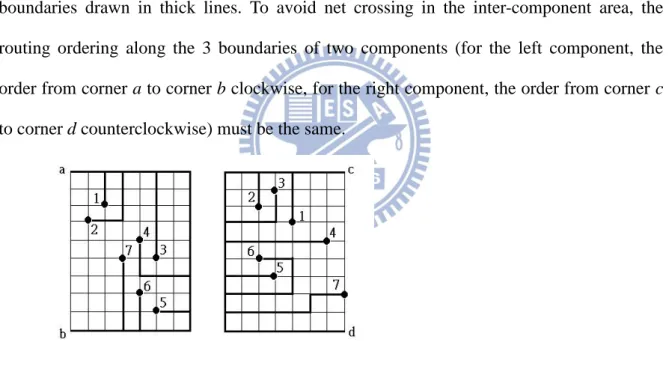
As shown in Fig 4, in simultaneous 2-component escape routing problem, the 2 components are face to face. The selected grid points to be routed are to escape to the three boundaries drawn in thick lines. To avoid net crossing in the inter-component area, the routing ordering along the 3 boundaries of two components (for the left component, the order from corner a to corner b clockwise, for the right component, the order from corner c to corner d counterclockwise) must be the same.
Fig 4 3-side escape routing
In B-escape [1], boundary routing strategy is used. Observation shows that if a pin is routed following the routing boundary, more space will be available for later pins. In this way, more pins will be able to escape route to the boundary. This leads to the boundary routing strategy: whenever we route a pin, we first route it to the routing boundary and then follow the boundary. After routing a pin, the routing boundary shrinks to exclude the routing
9 path of that pin.
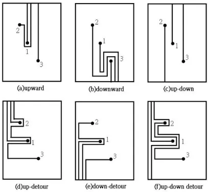
In [1], it is proved that if a routing solution exists, it can be captured by the boundary routing strategy. If we change the way we route from the pin to the routing boundary and the direction we follow the boundary, different routing styles can be created. Six routing modes were found simple and effective in B-escape [1] to get a boundary routing solution that meets the simultaneous escape routing problem, as shown in TABLE I.
TABLE I
DESCRIPTION OF SIX ROUTING MODES IN B-ESCAPE
Mode Routing description
Upward Route the pin straight up until it meets the boundary and then follow the boundary clockwise
Downward Route the pin straight down to the boundary and follow the boundary counterclockwise
Up-down Whenever routing in upward mode will completely block another pin, switch to downward mode and route the unrouted pin with the largest label
Detour upward Route each pin leftward to reach the boundary and then follow the boundary clockwise
Detour downward Route each pin leftward to reach the boundary and then follow the boundary counter-clockwise
Detour up-down Whenever routing in detour upward mode will completely block another pin, switch to detour downward mode and route the unrouted pin with the largest label
10 Fig 5 Six routing modes in B-escape [1]
3.3 Dynamic Net Ordering
According to the complexity of escape situations on PCBs, to find the correct ordering for the 2 components beforehand is next to impossible. Therefore, B-escape [1] uses a dynamic strategy to solve the ordering problem. The idea is to gradually determine the routing order as we route the nets. Whenever routing a new net, B-escape tentatively route each remaining net, evaluate the routing cost and pick the one with minimum cost. Cost vectors are compared with each other in lexicographical order, meaning that α is the most significant followed by β. The routing cost: a 2-element vector (α, β) is defined as follows.
α: the number of pins trapped (unroutable) by routing current net.
β: the number of pins blocked (but still routable) by current routing.(A pin is blocked by a net means the net blocks the projection from the pin to the escape boundary.)
11
Note that although we are only showing one component to demonstrate the cost idea, each cost element takes both components into account. For differential pair routing, (which is not mentioned in [1]) no matter when we are doing B-escape non-length-matching routing or our length-matching routing, we route the 2 pins of a differential pair in both components and count its differential pair cost.
Fig 6 Cost function
Though choosing the net with minimum cost at each step is a good idea, it cannot always guarantee the best routability, sometimes pins could be trapped by routed nets. Therefore, a reorder method is applied. The reorder method of B-escape [1] is described as follows. For each step, nets/pairs are sorted by its routing cost in non-decreasing order. The net/pair with minimum cost will be chosen. Once an unrouted pin is trapped by routed nets, backtrack to the step, where the cost difference between the first net/pair and the next candidate is minimum. Then the next candidate net/pair will be chosen instead and the routing process goes on. If more than one step have the minimum cost difference, we choose the step nearest to the reordering point. By reordering, the router can make sure that all the pins remain routable at each routing step. Fig 7 demonstrates the backtrack and reorder process. This process continues until either we find the solution as in this figure or the times of backtracking have exceeded the limit.
12
B-Escape loops through 6 routing modes from up mode to up-down detour mode and finally output the solution with the best routability.
13
Chapter 4. Length Matching Method
4.1 Overview
4.1.1 Differential pair routing constraints
Fig 8 Differential pair routing solutions
As mentioned in Section I, the two nets of a differential pair should be routed together. Fig 8 shows three routing solutions, the circles represent the pin nodes in the component, where Net a1 and Net a2 are a differential pair. The first one (a) satisfies differential pair routing constraint. The second one (b) is illegal, because the paired nets are separated by a row of pins. The third one (c) is also illegal because the paired nets are separated by another net.
4.1.2 Previous Works
In B-Escape [1], making differential pairs parallel to each other is achieved. To avoid the situation in Figure 8(b), two routing boundaries are maintained. For non-paired nets or single nets, the boundary was exactly defined by the previously routed nets as shown in Figure 9(a). Figure 9(b) shows how to adjust the single-net boundary for differential pair routing. The upper boundary is lowered so that there is one track right beneath the boundary. Figure 9(c) shows the routing of Net a1 obtained by tracing the paired-net boundary. Once
14
a1 is routed, Net a2 can be treated as a single net and its route is finished in Figure 9(d).
Fig 9 Differential pair routing method used in B-escape [1]
While the differential pair routing method in [1] did not solve length matching problem, a paper considering differential pair length matching problem in single-component escape routing [2] gives us an idea to solve it. The concept of min-cost median point which connects two pins by shortest and equal wire lengths helps us keep working on the problem.
4.2 Min-Cost Median Point Finding
Our Simultaneous escape router considering length matching of differential pairs is based on B-escape [1]. All nets/pairs are sequentially routed, counting their cost to get their routing order and once we reach the reordering point, backtrack is performed. Each time we route a differential pair, our length matching method is applied. The length matching routing method for differential pairs we use is described as follows.
Different from the differential pair routing strategy used in B-escape, we route the two nets of one differential pair at the same time. Here we use the concept of min-cost median
point mentioned in [2]. A min-cost median point for a differential pair is a median point
which has the shortest and equal Manhattan distances from the median point to the two pins of the differential pair. Since the Manhattan distance between the median point and the two
15
pins of the differential pair are equal, length matching of differential pairs can be achieved by two steps. First, we route from the two pins of a differential pair to a min-cost median point. Second, we route the two nets in a differential pair from the min-cost median point to the component boundary together.
Note that for each differential pair, the min-cost median points lies on tile nodes (see Fig 10), which is at the center of each four neighboring pins. Thus, differential pairs are no longer routed with grid structure with switch boxes in B-escape. Instead, differential pairs are routed through tile nodes to achieve length matching. As shown in Fig 11, the routing path represented in single line passing tile nodes will be transformed into parallel lines after routing.
Fig 10 Possible min-cost median points
Fig 11 Transform from single line tile route to 2-line parallel route
In order to find min-cost median points, we use an efficient algorithm called MCMPF [2] (Min-Cost Median Point Finding) to find the min-cost median points for each differential pair. Once the position of the two pins of a differential pair is given, MCMPF algorithm can find all possible min-cost median points. As shown in Fig 14, 1a and 1b is a differential pair, and a, b, c, d are four possible median points for the differential pair.
16
4.3 Shortest Pin-to-Pin Path through Median Point Enumerating
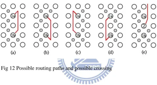
After all median points of the differential pair are found, since there may be more than one possible median points for one differential pair and more than one suitable paths for the chosen median point, the next step is to choose one median point and a valid pin-to-pin path for the differential pair. As shown in Fig 12, we list four of eight possible pin-to-pin paths for 1a and 1b, (a), (b), (c), (d). In (e), if Net 2 is routed beforehand, routing the possible pin-to-pin paths (a) and (b) would cause crossings. Therefore, it is necessary to check the routability of each possible solution before routing them.
Fig 12 Possible routing paths and possible crossing
Now, the problem is, among the possible median points and pin-to-pin paths, which solution is the best? When we are choosing a good median point and a valid pin-to-pin path, we sort the possible median points and pin-to-pin paths through the median points first and then sequentially check whether the pin-to-pin path would cross another routed net. If the first candidate chosen would cross another routed net, we check the next candidate and move on until a solution is found.
To improve routability, we sort the candidates of median points and pin-to-pin paths by the space left for other unrouted nets after routing it. Different median point and pin-to-pin path would leave different routing space for the unrouted pins. If a median point and a pin-to-pin path chosen could leave more routing space for the other nets than another
17
one, then it is a better candidate. For example, when we are routing the left component with up mode, as shown in Fig 10 and Fig 13, since choosing tile b as median point leaves more routing space for other unrouted pins than choosing tile a, c, and d, tile b is a better median point candidate. In this case, we first choose the median points with the biggest y-axis, then the median point with the biggest x-axis. After we have chosen a median point, there could be several possible pin-to-pin paths through the median point. As shown in Fig 13, there are two possible pin-to-pin paths pass through the same median point (tile b in Fig 14). We first choose the pin-to-pin paths whose smallest point in y-axis is the biggest, then the pin-to-pin path whose smallest point in x-axis is the biggest. The pin-to-pin path in (a) is a better candidate than (b) because (a) leaves more routing space for the other unrouted pins.
Fig 13 2 pin-to-pin paths through the same median point
Note that as routing mode changes, the priority of the same routing candidate changes. For example, as shown in Fig 12, (a) has a higher priority than (b) when routing up mode/up-detour mode, while (b) has a higher priority than (a) when routing down/down-detour mode, depending on the routing space left for unrouted nets after routing them.
4.4 Median-Point-to-Boundary Path Determination Considering
Net Ordering
18
route from min-cost median point to the component boundary. Here the boundary routing strategy [1] is applied on the selected median point, therefore, a routing path from median point to the component boundary is obtained.
In this step, we should notice that when we are routing from min-cost median point to the component boundary, the differential pair net ordering must be taken into consideration; otherwise crossing may occur in the inter-component area. Fig 14 shows the routing result without considering the net ordering of differential pairs, where 1a and 1b, 1A and 1B are corresponding differential pairs in two components.
Fig 14 Wrong ordering of differential pairs in two components
In order to avoid crossings in the area between components, net ordering should be considered. Our discussion and solution are described as follows.
When we are routing differential pairs, we route the differential pair in the first component, then the second, therefore, the net ordering of differential pairs is decided by the routing result in the first component. To match the net ordering of differential pairs in two components, the net ordering in the second component must meet that of the first component. By observation, we find that there are four directions, “up”, “down”, “left” and “right” for each median point to do tile to tile boundary route at the median-point-to-boundary routing stage. And the net ordering of differential pairs at the boundary are decided by the relative position of the pins of a differential pair and the direction the median point goes at the median-point-to-boundary routing stage. As a result,
19
after the median point and pin-to-pin path are selected in the second component, when we are routing from the median point to the boundary, we need to check whether the direction the median point goes to will cause the same net ordering as the first component. If a proper routing direction is selected for the median point in the second component, no crossings will occur in the inter-component area.
For example, if we route the left component first in Fig 14, routing the median point in the right component to “left” would cause crossing. In contrast, in Fig 15, if we route the median point in the right component to “up”, the ordering of the differential pair in the two components will be matched.
Fig 15 Routing direction “up” in the 2nd component
Fig 16 No proper routing direction for the 2nd component
If we always route the left component first, then the right component, crossings can still occur. Sometimes we cannot find a proper direction for the median point in the right component to meet the routing ordering of the first component. As shown in Fig 16, if we route the left component first, the median point in the right component can only go to the “left” direction, causing a crossing in inter-component area. In this case, we will try to route
20
the right component first, the left component second and check whether the direction the median point in the left component goes to will get the same net ordering as the right component. As shown in Fig 17, we route the differential pair in the right component first, the median point in the left component can be routed in a proper direction to meet the ordering of the differential pair in the right component.
Fig 17 Route the right component first
By the discussion written above, Fig 18 shows the Differential Pair Routing Considering Length Matching Algorithm. Each time we route a differential pair in simultaneous 2-component ordered escape routing based on B-escape, the algorithm is applied. We route the differential pair in the left component first and the right component second. If no path is found, we route the differential pair in the right component first and the left component second.
21
22
Chapter 5. Experimental Results
Our router is implemented in C++ and experiments are performed on a Intel Xeon E5620 CPU system with 70GB memory. We test 4 test cases which are generated according to the information of the distribution of the distances between the two pins of a differential pair from [4]. To better compare the routability, in non-length-matching B-escape router, when a pin at the component boundary does escape routing, it occupies a track of routing capacity beside it. Finally, in our implementation of non-length-matching B-escape router [1], given a differential pair 1a and 1b, if sequentially routing 1a and 1b will cause a failure while routing 1b first and 1a second is a success, the routing process will continue without backtracking.
TABLE I shows the benchmark information and experimental results, where “# diff
pair” gives the number of differential pairs, “#Row*#Col” gives the size of the left and right
component, and “equal len. rate” gives the rate of length matching of differential pairs. Experimental results show that our work can achieve 100% routability in all test cases while B-escape cannot route all the differential pairs on Case 4. We achieve 100% differential pair length matching, while no differential pairs are length matched in the result of B-escape. Because B-escape does not designed to do length matching of differential pairs, it is almost impossible for a differential pair in both components to obtain length matching result. By experiments in [2], with our length matching result of simultaneous escape routing of differential pairs, differential pair skews can be well improved. Finally, our work greatly reduces the run time than that of B-escape. There can be two reasons. First, each time non-length-matching B-escape routes a differential pair, the 2 nets of it are routed separately, and boundary routing are executed two times. In contrast, our work routes the 2 nets of a differential pair together at one time, and boundary routing are only executed once. Second, due to the switch box structure, there are more possible routing directions to check in each
23
routing stage for the non-length matching B-escape router. In summary, our work accomplishes simultaneous escape routing considering length matching of differential pairs and uses less time than B-escape.
Fig 19, 20 show the differential pair routing result of case 2 obtained by our work and B-escape, where “number” and “number*” make a differential pair.
TABLE II
BENCHMARK INFORMATION AND EXPERIMENTAL RESULTS
Case Left component #Row*#Col Right component #Row*#Col #Diff. pair Non-length-matching B-escape[1] Our work Routability Runtime(s) Equal len. rate Routability Runtime(s) Equal len. rate 1 10*10 10*10 5 100% 0.69 0% 100% 0.04 100% 2 14*14 14*14 10 100% 26.37 0% 100% 0.64 100% 3 14*14 14*14 12 100% 41.02 0% 100% 1.25 100% 4 20*20 20*20 20 96% 1678.45 -- 100% 15.44 100%
24
25
Chapter 6. Conclusions
In this thesis, based on the B-escape routing algorithm [1] and the idea of min-cost
median point used in differential pair length-matching strategy [2], we implement a work
that achieves simultaneous escape routing considering length matching of differential pairs. On routing differential pairs, we first find a min-cost median point and a pin-to-pin path through the median point that guarantee equal wire length. Second, apply boundary routing to the median point to get the path from median point to boundary. Experimental results show that our approach can efficiently and effectively obtain length-matching of differential pairs on simultaneous escape routing to reduce differential-pair skews with less running time than the original B-escape router.
26
Bibliography
[1] L. Luo, T. Yan, Q. Ma, D. F. Wong and T. Shibuya, “B-escape: a simultaneous escape routing algorithm based on boundary routing,“ in Proc. of ACM International Symposium on Physical Design, pp.19-25, 2010.
[2] Tai-Hung Li, Wan-Chun Chen, Xian-Ting Cai, and Tai-Chen Chen, “Escape routing of differential pairs considering length matching,” in Proc. of IEEE Asia and South Pacific Design Automation Conference, pp. 139–144, 2012.
[3] C. T. Robertson, Printed Circuit Board, Prentice Hall, 2004.
[4] T. Yan, P. C. Wu, Q. Ma, and Wong, M.D.F., "On the escape routing of differential pairs," in Proc. of IEEE/ACM International Conference on Computer-Aided Design, pp. 614-620, 2010.
[5] M. M. Ozdal and M. D. Wong, “Simultaneous escape routing and layer assignment for dense PCBs,” in Proc. of IEEE/ACM International Conference on Computer-Aided Design, pp. 822–829, 2004.
[6] M. M. Ozdal, M. D. Wong, and P. Honsinger, “Simultaneous escape routing algorithms for via minimization of high-speed boards,” in Proc. of IEEE Transactions on Computer-Aided Design of Integrated Circuits and Systems, volume 27, pages 84–95, 2008.
![Fig 1 Simultaneous escape routing [1]](https://thumb-ap.123doks.com/thumbv2/9libinfo/8653138.194166/10.892.182.433.800.1055/fig-simultaneous-escape-routing.webp)
![Fig 9 Differential pair routing method used in B-escape [1]](https://thumb-ap.123doks.com/thumbv2/9libinfo/8653138.194166/23.892.232.489.156.410/fig-differential-pair-routing-method-used-b-escape.webp)