國
立
交
通
大
學
電子工程學系 電子研究所碩士班
碩 士 論 文
時脈樹和正反器重新散布之共同合成方法
Cosynthesis of Clock Tree and Flip-Flop Redistribution
研 究 生:羅琬婷
指導教授:陳宏明 教授
時脈樹和正反器重新散布之共同合成方法
Cosynthesis of Clock Tree and Flip-Flop Redistribution
研 究 生:羅琬婷 Student:Wan-Ting Lo
指導教授:陳宏明 Advisor:Hung-Ming Chen
國 立 交 通 大 學
電子工程學系 電子研究所碩士班
碩 士 論 文
A ThesisSubmitted to Department of Electronics Engineering and Institute of Electronics
College of Electrical and Computer Engineering National Chiao Tung University
in partial Fulfillment of the Requirements for the Degree of
Master of Science in
Electronics Engineering
Aug 2011
Hsinchu, Taiwan, Republic of China
時脈樹和正反器重新散布之共同合成方法
學生: 羅琬婷
指導教授: 陳宏明 教授
國立交通大學 電子工程學系 電子研究所 碩士班
摘
要
在這篇論文中,我們提出了一種優化方法為使用自下而上的群聚
的正反器來降低功耗以及將信號線長最小化。比較以往對於減少正反
器的研究,我們的方法能達到在正反器的功耗和減少信號線長之間的
最佳優化。我們所提出的方法在正反器的功耗和減少信號線長方面優
於[3]和[14]。與[8]比較,我們的方法可以減少 15.8%的信號線長以及
增加 1.8%的正反器功耗。由於自下而上群聚方式的特性,我們提出
的方法對於初始配置能夠達到最小的擾動。
我們進一步改善我們的方法,結合時鐘樹合成,利用 K -means 分
群法識別正反器的群集和更換正反器處於最佳時鐘樹的位置,這樣可
以減少功耗。實驗結果表明,我們的交錯機制可以達到最佳的時鐘樹
功耗。
我們從所有以前出版的著作[3] [14] [8]獲得執行檔和評估執行結
果使用完全相同的參數。正反器的最終位置轉換為 ISPD2010 標準格
式[13]以及使用 NGSPICE[1]評估最後的時鐘樹合成結果。
Cosynthesis of Clock Tree and Flip-Flop Redistribution
Student: Wan-Ting Lo Advisor: Prof. Hung-Ming Chen Department of Electronics Engineering
Institute of Electronics National Chiao Tung University
ABSTRACT
In this thesis, we propose an optimization methodology using agglomerative clus-tering for flip-flop’s power reduction and signal wirelength minimization. Comparing to previous works on flip-flop reduction, our method can reach the best optimization between flip-flop’s power and signal wirelength reduction. Our proposed methodol-ogy outperforms [3] and [14] in both flip-flop’s power and signal wirelength reduc-tion. Comparing with [8], our methodology can reduce signal wirelength by 15.8% with 1.8% increase in flip-flop power consumption. Due to the nature of agglom-erative clustering, our proposed method also creates least perturbation to original placement.
We further improve our method by integrating with clock tree synthesis using k-means clustering to identify cluster of flip-flop and replace flip-flop in an optimal location such that clock tree power consumption can be reduced. Experimental result demonstrates that our interleaving mechanism can reach the best clock tree power consumption.
We obtained binaries from all of the previous published works[3][14][8] and eval-uate them using exact same parameter. The final location of flip-flop is converted to ISPD 2010 benchmark format[13] and final result of clock tree synthesis is evaluated using NGSPICE[1].
誌
謝
本論文的完成首先要感謝指導老師陳宏明教授,在研究和論文撰寫方面給了 很多寶貴的意見,也很感謝老師的開明讓我在研究上有非常大的發揮空間。 另外也要特別感謝我的口試委員,分別是王廷基教授、江蕙如教授和趙家佐 教授,在口試的時候提出寶貴的意見和建議。 而在研究方面,首先最感謝的是劉時穎給我明確的研究方向,以及不辭勞苦 的幫我看程式和修改口試投影片。感謝 97 級的佳蕙、奕蓉和 98 級的欣吳、永證、 長毅、逸芃、業琦跟我一起為作業海和畢業奮鬥,感謝博班們,包括敬雨、時穎、 杰叡、柏丞、俊凱、篤雄在研究上和生活上的陪伴,希望你們都能很快集滿點數 準時畢業。 感謝我的父母,在學業上和經濟上全力的支持,讓我能夠順利地度過漫漫求 學長路。
Contents
Abstract (Chinese) i Abstract ii Acknowledgements iii Contents iv List of Tables viList of Figures vii
1 Introduction 1
1.1 Previous Works . . . 2
1.1.1 Optimization during placement stage . . . 3
1.1.2 Optimization at post-placement stage . . . 3
1.2 Our Contributions . . . 4
2 Problem formulation 7
3.1 Resemblance between agglomerative clustering and nearest neighbor
selection . . . 8
3.2 Overlap graph construction using agglomerative clustering . . . 9
3.3 Flip-flop merging . . . 13
3.4 Placement of Flip-Flop . . . 14
3.4.1 Flip-Flop Library . . . 14
3.4.2 Slack and Timing Constraint . . . 14
3.4.3 Placement Density Constraint . . . 15
4 K-means based clock tree synthesis 17 4.1 k-means clustering . . . 18
4.1.1 Lloyd’s algorithm . . . 19
4.2 Improved k-means clustering . . . 20
5 Interleaving clock tree generation with flip-flop merging 22 5.1 Interleaving procedure . . . 23
6 Experimental results 26 6.1 Flip-Flop’s Power and Signal Wirelength Reduction . . . 27
6.2 Result of Clock Tree Synthesis After Flip-Flop Merging . . . 29
List of Tables
2.1 Bit, Power and Area for each Flip-Flop Type . . . 7 6.1 Comparison on Flip-Flop Number Reduction and Detail of Multi-Bit
Flip-Flop For Each Testcase . . . 30 6.2 Comparison on Flip-Flop’s Power Reduction, Flip-Flop’s Signal
Wire-length and Execution Time . . . 31 6.3 Comparison on Average Displacement Distance of Merged Flip-Flops 32 6.4 Comparison on Clock Tree Synthesis Results including Sink, Buffer
and Wire Capacitors after Multi-Bit Flip-Flop Construction among [8], [14], [3], and Our Work with and without Interleaving Technique . 32
List of Figures
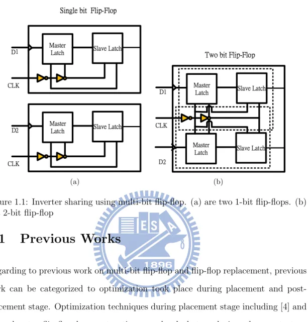
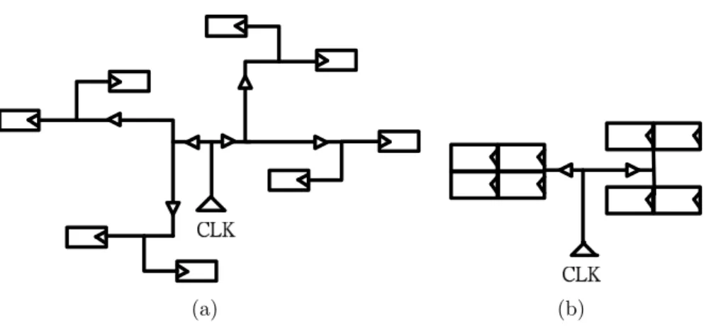
1.1 Inverter sharing using multi-bit flip-flop. (a) are two 1-bit flip-flops. (b) is a 2-bit flip-flop . . . 2 1.2 Reduction of sinks in clock tree. (a) is an illustration of a clock signal
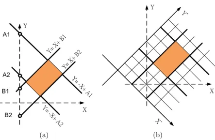
connecting to eight 1-bit flip-flop. (b) is an illustration using multi-bit flip-flop. . . 3 3.1 The rotate coordinate system to describe flip-flop movable zone(a)
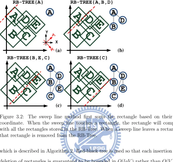
depicts the rotated coordinate system by 45 degrees. (b) coordinates representation for rotated rectangle. . . 9 3.2 The sweep line method first sorts the rectangle based on their
X’-coordinate. When the sweep line touches a rectangle, the rectangle will compare with all the rectangles stored in the RB-Tree. When a sweep line leaves a rectangle, that rectangle is removed from the RB-Tree. . . 11 3.3 Example of agglomerative clustering in flip-flop merging . . . 14 3.4 Placement of Merged Flip-Flop . . . 15 4.1 Illustration of coarsen and un-coarsen methodology to construct
4.2 An example of k-means algorithm. (a) Randomly select 3 means which are shown in circle. (b) Assign sinks to the nearest means. (c) New centroid of each cluster are generated. (d) All sinks are reassigned to the new means, and the partitions which are generated by 3 means represent the Voronoi Diagram. . . 19 4.3 The first phase of improved k-means clustering. (a) The first center
shown in colored square is randomly selected. (b) Calculate each sink probability with respect to the first center. (c) Select the sink with highest probability to be the second center. (d) Calculate probability with respect to both centers, then decide the third center. . . 20 5.1 The effect of CTS due to selection of flip-flop merge. (a) is the
orig-inal sink distribution (b) consructs the graph in FF-Merge (c) is an example of sink distribution with uneven load and (d) is an example of sink distribution with even load. . . 22 5.2 An example of interleaving CTS and FF-Merge. (b) draws out the
slack-TRR of all FF. (c) constructs graph according to TRR in (b). (d) performs the un-coarsening phase in CTS. (e) updates the edge cost (f) performs one iteration of FF-Merge. (g) performs un-coarsening phase in CTS one more time. (h) constructs the clock tree based on DME. . . 24 6.1 Illustration of the flip-flop merging result on testcase C3. (a) Original
case(b) Result of [8](c) Result of [14](d) Result of [3](e) Result of Our work without interleaving(f) Result of Our work with interleaving . . 27
Chapter 1
Introduction
In modern SoC design flow, recent research in industry and academia discovered that flip-flops in advance technology require less driving power. Less driving power for flip-flop indicates that a single inverter can drive multiple flip-flop which introduces the possibility to implement multi-bit flip-flop.
Multi-bit flip-flop has the advantage to share common inverter to reduce power consumption per bit and allow flip-flop layout area to be more compact. In addition, implementation of multi-bit flip-flop can reduce both sink number and sink capaci-tance. The reduction in sink number implies less clock tree wirelength which trans-lates to lower clock tree power consumption. However, implmentation of multi-bit flip-flop has the drawback of increasing in flip-flop’s signal wirelength. Experimental result shows the improvement in power reduction by greedily merging flip-flop will eventually saturate due to increase in flip-flop’s signal wirelength.
In addition to sink number, placement of flip-flop will also affect clock tree power consumption. It is shown in [11] that clock tree wirelength can be reduced up to 33% when topology of clock tree is considered during placement stage.
(a) (b)
Figure 1.1: Inverter sharing using multi-bit flip-flop. (a) are two 1-bit flip-flops. (b) is a 2-bit flip-flop
1.1
Previous Works
Regarding to previous work on multi-bit flip-flop and flip-flop replacement, previous work can be categorized to optimization took place during placement and post-placement stage. Optimization techniques during post-placement stage including [4] and [11] relocates flip-flop by constructing pseudo clock tree during placement stage or integrate multi-bit flip-flop to existing library to reduce sink number. Figure 1.1 illustrates the implementation of a 2-bit flip-flop. A multi-bit flip-flop has the advantage to share common inverter comparing to 1-bit flip-flop. Figure 1.2 depicts how sink reduction affects the topology of a clock tree.
Post-placement optimization including [3][14][8] replaces serveral flip-flop with one multi-bit flip-flop and relocates the multi-bit flip-flop to minimize the total signal wirelength from all of its connected pins. The valid region for a flip-flop to be relocated is defined by the slack value from all of its connected pins.
(a) (b)
Figure 1.2: Reduction of sinks in clock tree. (a) is an illustration of a clock signal connecting to eight 1-bit flip-flop. (b) is an illustration using multi-bit flip-flop.
1.1.1
Optimization during placement stage
Regarding to flip-flop replacement, Lee et al. [11] integrates a virtual clock tree with its previously published force-directed placer [9]. In each iteration of placement, a virtual clock tree will be constructed to identify the topology of clock tree. A contraction force will then be applied on each flip-flop to motiviate flip-flops to group into clusters. Eventually, clock tree wirelength can be reduced by reshaping the clock tree. Final clock tree synthesis is delegated to [10] for final evaluation. Experimental result shows that modifying sink position can reduce clock tree wirelength by 30% difference and 7% reduction in dynamic power consumption.
1.1.2
Optimization at post-placement stage
In terms of optimization of flip-flop at post-placement stage, all three of [14][3][8] shares same objective by optimizing between flip-flop and signal wirelength reduc-tion. Given a set of flip-flop library, placement density constraint and slack con-straint, flip-flop reduction is achieved by merging flip-flop to appropriate higher bit flip-flop. The main difference between the three works lies on selecting groups of flip-flop to be merged.
op-timization. As window sweeps across given layout, an intersection graph will be constructed within the window. The intersection graph is constructed with node represnting flip-flop and edge represents that two flip-flop can be safely merged without violating slack constraint. After intersection graph is constructed, maximal independent set of cliques can be identified. Each set
Similar to [3], Wang et al. [14] also model the given problem as graph problem. The difference is that [14] applies minimum clique partition problem to identify a set of non-conflicting cliques. In addition, a clock tree synthesis using [5] is applied to demonstrate reduction in dynamic power and clock tree wirelength.
In constrast to [14] and [3], Jiang et al. [8] proposed a linear-size sequence repre-sentation to quickly identify optimal clustering combinations. Based on coordinate transformation, [8] generate interval graph corresponding to each flip-flop’s feasible region with both X and Y direction. The X direction interval graph provides deci-sion points to obtain essential flip-flops and the Y direction interval graph provides maximal clique for each essential flip-flops. Compare to [14] and [3], [8] can achieve most flip-flop reduction within fastest runtime.
1.2
Our Contributions
Despite previous effort in flip-flop merging, none considered the chacteristic of clock tree when determining flip-flop relocation position. It is demonstrated in [11] that modifying sink position can achieve significant improvement in clock tree power consumption.
Regarding to [14] [3][8], a trade off between signal wirelength and flip-flop reduc-tion can be observed. Greedily reducing flip-flop by merging flip-flop will increase signal wirelength dramatically. Power reduction achieved using multi-bit flip-flop will eventually be counteracted by increase in signal wirelength power consumption.
In [3], both signal wirelength and flip-flop reduction trails behind [8] and [14]. The inherent characteristic of window-based optimization prevents a global view of the entire problem. In [14], although clock tree synthesis is performed after flip-flop merging, the location flip-flop is unaffected by the clock tree synthesis. In addition, the clock tree synthesis performed in [14] is an unbuffered clock tree synthesis which lacks detail in buffer power consumption and lacks evaluation with spice model.
In [8], although flip-flop number is greatly reduced, it is achieved with a great expense in increasing in signal wirelength. In addition, more flip-flop reduction entails higher peturbation to original layout which adds burden to final legalization stage.
In this thesis, we applied flip-flop merging using agglomerative clustering. In con-strast to previous work, we merge flip-flop in a bottom-up fashion. Flip-flop merging is performed by choosing pair of flip-flop with least increase to signal wirelength. Such approach can guarantee that total increase in signal wirelength is minimized with equivalent flip-flop number reduction. Unlike [3] and [14], our approach avoids identifying maximum clique which is unneccessary when given multi-bit flip-flop library is limited.
To optimize clock tree power consumption, we integrate our implementation of buffered clock tree synthesis with flip-flop merging, a pseudo clock tree based on k-means clustering is performed at each iteration of flip-flop merge to determine optimial relocation position for flip-flop to reduce clock tree wirelength.
All in all, our contribution in this work can be summarized as follows.
• Our agglomerative clustering based flip-flop merging can reach the best opti-mization bewteen flip-flop’s power reduction and signal wirelength.
• We proposed a k-means based clock tree topology construction to quickly identify cluster of flip-flops based on their physical location.
• We proposed a methodology to interleave clock tree synthesis with flip-flop merging to optimize clock tree power consumption.
The following sections are organized as follows: Chapter 2 defines problem formu-lation. Chapter 3 describes agglomerative clustering for flip-flop merging. Chapter 4 introduces a k-means based clock tree topology construction. Chapter 5 describes the interleaving mechanism of flip-flop merging and clock tree synthesis. Chapter 6 presents the experimental result and finally Chapter 7 concludes the thesis.
Chapter 2
Problem formulation
The problem of clock tree synthesis considering flip-flop merging can be defined as follows. Given a set of m-bit flip-flop library in Table 2.1 and a set of flip-flop each with a slack value, using the given multi-bit flip-flop to reduce sink number and place the merged flip-flop in position without violating any slack and placement density constraint. Next, we construct a clock tree with merged flip-flop that minimizes the total wirelength without violating any slack and placement density constraint.
Table 2.1: Bit, Power and Area for each Flip-Flop Type
Name Bit# Power Area Power/Bit Area/Bit
FF1 1 100 100 100 100
FF2 2 172 192 86 96
Chapter 3
Agglomerative clustering based
flip-flop merging
When dealing with flip-flop merging, determining which set of flip-flops to be merged should closely relate to sink merging in clock tree synthesis. Nearest Neighbor Selection(NNS) proposed by [7] is one of the popular methods to construct topology of clock tree. NNS first constructs a relation graph that calculates the nearest neighbor sink to every sink. After relation graph is constructed, edge with smallest distance between two sinks will be picked and merged as new sink and insert back to the relation graph. The process iterates until there is only one sink left in the relation graph. Thus, when a flip-flop selects the best merging candidate, flip-flop within nearest proximity should be selected. The benefit of such approach is two-fold. First, wirelength connecting to both merged flip-flop can be minimized. Second, the relocation position of merged flip-flop will not deviate too much from its original position.
3.1
Resemblance between agglomerative
cluster-ing and nearest neighbor selection
In short, NNS is a bottom-up approach that constructs a tree by selecting minimum cost edge in each iteration. The agglomerative(bottom-up) approach in hierarchical
Y X Y= -X+ A1 Y= -X+ A2 Y= X+ B1 Y= X+ B2 A1 A2 B1 B2 (a) Y X Y’ X’ (b)
Figure 3.1: The rotate coordinate system to describe flip-flop movable zone(a) de-picts the rotated coordinate system by 45 degrees. (b) coordinates representation for rotated rectangle.
clustering takes very similar approach compared to NNS. Agglomerative clustering iterates and merges two clusters with minimum cost based on certain cost function until one single cluster that contains all elements is formed. The major difference between agglomerative clustering and NNS is that graph constructed in agglomera-tive clustering calculates the distance between every single pair of sinks, while graph constructed in NNS only shows the nearest neighbor sink for a given sink.
3.2
Overlap graph construction using
agglomera-tive clustering
The slack value for a flip-flop can be treated as a distance budget for a flip-flop. The farther away flip-flop moved from its original location, the less slack value a flip-flop has. In this regard, the slack value for a flip-flop can be modeled as a form of wire delay. The distance in this context refers to Manhattan distance, thus the region a flip-flop can be relocated without violating the given slack constraint forms a tilted rectangle region (TRR). The TRR for flip-flop merging takes the same concept of TRR in clock tree except that TRR in flip-flop merging has radius defined by its
Algorithm 1 Segment-Overlap Segment-Overlap(ni,nj)
1: if min[ni] ≤ min[nj] and min[nj] ≤ max[ni] then
2: return true
3: else
4: return false
5: end if
slack value while the radius for TRR in clock tree is defined by its capacitance load. If two flip-flop’s TRR overlaps, it implies that two flip-flop can safely be merged in the overlapping region without violating slack constraint for both flip-flops. In graph representation, flip-flop is represented by a node and overlapping region of two flip-flops is represented by an edge. An edge is created between two flip-flops if and only if there exists an overlapping region between the two flip-flops.
The naive implementation of agglomerative clustering has time complexity O(N2)
which is to compare every node with every other node. However, not every node has an edge connecting to every other node. A more efficient approach is to sort all the rectangles on X-coordinate and find overlapping segment in Y-coordinate which can reduce number of comparisons. This approach is derived from Line Sweep Method[6]. Red-black tree is also used so that each insertion and deletion of TRR is guaranteed to be bounded in O(lgN ) rather than O(N ).
We formulate the flip-flop merging problem as a graph problem. In graph, node represents a flip-flop movable zone which is a rotated rectangle and edge represents there exists overlapping region between two nodes it connects. To identify all the overlapping rectangles, the straight forward method is to compare one rectangle with every other rectangle. However, it is rare that every rectangle overlaps with every other rectangle. A more efficient approach is to sort all the rectangles on X-coordinate and find overlapping segment in Y-X-coordinate which can reduce number of comparisons. This approach is commonly known as Line Sweep Method [6],
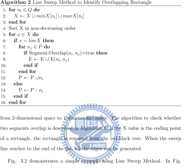
Figure 3.2: The sweep line method first sorts the rectangle based on their X’-coordinate. When the sweep line touches a rectangle, the rectangle will compare with all the rectangles stored in the RB-Tree. When a sweep line leaves a rectangle, that rectangle is removed from the RB-Tree.
which is described in Algorithm 2. Red-black tree is used so that each insertion and deletion of rectangles is guaranteed to be bounded in O(lgV ) rather than O(V ).
The algorithm first takes all rectangle’s minimum and maximum X-coordinates and store them in an array. The X-coordinates will then be sorted in non-decreasing order using heap sort which corresponds to line 1-4 in Algorithm 2. After the array is sorted, an imaginary line starts to sweep from the beginning of the array. If the X value is the starting point of a rectangle, the rectangle is stored into a red-black tree and compare with all the rectangles stored in the red-black tree to check whether if there exists overlapping region between the two rectangles. Given that rectangles are already sorted by their X-coordinate, if two rectangles were to be compared, then it implies that two rectangles must be overlapped in X-coordinate. Hence, checking whether if two rectangles exist overlapping region only needs to check whether the segments of two rectangle are overlapped in Y-coordinate, which reduces the problem
Algorithm 2 Line Sweep Method to Identify Overlapping Rectangle
1: for ni ∈ Q do
2: X ← X ∪ minX[ni] ∪ maxX[ni]
3: end for
4: Sort X in non-decreasing order
5: for x ∈ X do
6: if x = lowX then
7: for nj ∈ P do
8: if Segment-Overlap(ni, nj)=true then
9: E ← E ∪ E(ni, nj) 10: end if 11: end for 12: P ← P ∪ni 13: else 14: P ← P - ni 15: end if 16: end for
from 2-dimensional space to 1-dimensional space. The algorithm to check whether two segments overlap is described in Algorithm 1. If the X value is the ending point of a rectangle, the rectangle is removed from the red-black tree. When the sweep line reaches to the end of the list, all the edges can be generated.
Fig. 3.2 demonstrates a simple example using Line Sweep Method. In Fig. 3.2(a), sweep line first enters rectangle A and rectangle A is stored in the red-black tree. In Fig. 3.2(b), sweep line enters rectangle D. Rectangle D are then compared with rectangle A and B to check whether if there exist overlapping region. In Fig. 3.2(c), sweep line leaves rectangle D which is removed from the red-black tree. Finally, in Fig. 3.2(d), the sweep line leaves rectangle E and rectangle E is removed. In worst case scenario in which every rectangle overlaps with every other rectan-gles, the graph representation of such circumstance is a complete graph. The time complexity for Line Sweep Method in a complete graph is O(N2) since no rectangles
will be removed from red-black tree and every inserted rectangle must compare with every other rectangles stored in the red-black tree.
Algorithm 3 Hierarchical Agglomerative Clustering HAC(Q) 1: while Q!=EMPTY do 2: Edge ← Pop[Q] 3: RB− T REE ← ∅ 4: nl ← Left[Edge] 5: nr ← Right[Edge]
6: if (Bit[nl] + Bit[nr]) ∈ FF-Library then
7: nnew = new Node
8: nmergeable← f indCommonN ode(nl, nr)
9: Enew = new Edge(nmergeable, nnew)
10: Q← Q ∪ Enew
11: end if
12: end while
3.3
Flip-flop merging
After graph is constructed, the edge with minimum cost will be selected and checked whether if it is mergeable. For two flip-flop to be mergeable, there must exist corresponding type in given flip-flop library. For example, if FF-A is 1-bit, FF-B is 2-bit and there is no 3-bit flip-flop available, FF-A and FF-B can not be merged. In each iteration, each merge will select two flip-flops with least edge cost. If two flip-flops is successfully merged, new node representing the merged flip-flop will be created and added to the graph with corresponding edges. Edges connecting to two original flip-flops will be removed from the graph and new edges connecting to merged flip-flop will be added.
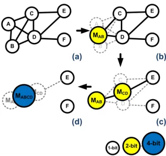
The algorithm will terminate until there is no more edge left in the graph. In Fig. 3.3(a), node A and B are picked to be merged, edges connected to node A and node B are removed. In Fig. 3.3(b), new node MAB is created with two new edges
added to the graph. Fig. 3.3(c) illustrates the same concept of merging node MAB
and node MCD to a 4-bit node MABCD. The algorithm terminates in Fig. 3.3(d)
A B C D E F A B C D E F C D E F
1-bit 2-bit 4-bit
(a) (b) (c) (d) MAB MAB MCD E F MAB MCD MABCD
Figure 3.3: Example of agglomerative clustering in flip-flop merging
3.4
Placement of Flip-Flop
3.4.1
Flip-Flop Library
Flip-flop can not be merged to any arbitrary higher bit flip-flops. There are limited flip-flop types and every single flip-flop must have a corresponding flip-flop type in the flip-flop library. Table 1 lists all the available flip-flop types in this work.
3.4.2
Slack and Timing Constraint
The location of the clustered flip-flop must be placed in a distance that does not violate the original slack constraint. There is a slack value for each flip-flop to each pin it connects to. f fi and pj in (3.1) denotes flip-flop and pin respectively. F F
denotes flip-flop set and P in denotes pin set connected to a certain flip-flop. For each connected flip-flop and pin, the distance between the two must not violate the given slack constraint.
Figure 3.4: Placement of Merged Flip-Flop
3.4.3
Placement Density Constraint
When placing flip-flops, density of the circuit must be considered. The given layout is partitioned into different set of bins, each bin is given with a placement density constraint and pre-placed combinational logic. The final placement density after flip-flop clustering must not violate the placement density constraint for all bins. In (3.2), B is the given set of bins, CAj denotes the combinational area in bin bj, the
summation of all flip-flop area and the combinational logic area in one bin can not exceed its pre-defined placement density constraint.
Pk
j∈biArea(f fj) + CAj
wi· hi
≤ Dmax, f or all bi ∈ B (3.2)
For a merged flip-flop to be successfully relocated, three conditions must be satisfied.
• Placement density for all bins can not be violated.
• The position of merged flip-flop must not overlap with other merged flip-flop. The given layout is partitioned into a set of bins and placement density is calcu-lated for each bin. When relocating a merged flip-flop, it will first check whether the relocation point is being occupied and whether the placement density of the corresponding bin is violated. If violated, a breadth-first search will be conducted to search for a nearest unoccupied point in which both slack and placement density are not violated. If such point does not exist, the merged flip-flop will split and return to its original state.
When flip-flop merge runs stand alone from clock tree synthesis, the mean point of all the pins connected to merged flip-flop will be selected as the relocation position of the merged flip-flop. When interleaved with clock tree construction which will be discussed in Chapter 5, a preferred merge position will be generated from CTS and fed to flip-flop merging. A breadth-first search will be conducted to search for the nearest valid point to the preferred merging position.
It should be noted that Nearest Neighbor Selection (NNS) and agglomerative clustering shares similar quality for wirelength minimization. However, NNS re-stricts one edge for each node which is not suitable to implement flip-flop merging. In flip-flop merging, not every pair of sink can be merged due to slack constraint and limited types of flip-flop in flip-flop library. In addition, to cope with clock tree synthesis, edge cost is required to update constantly. Agglomerative clustering in this regard is much more flexible and its high resemblance to NNS making it an optimal choice for flip-flop merging.
Chapter 4
K-means based clock tree
synthesis
In this section, a two phase clock tree topology construction based on improved k-means clustering is proposed. The first phase of clock tree topology construction is an un-coarsening phase that separates k most distant cluster in each iteration and terminates until there is less than three sinks in each cluster. The second phase is a coarsening phase which constructs a binary tree that takes the cluster formed in first phase and iteratively clusters them together until one single cluster is formed. The benefit of k-means is that it can quickly identify k pair of sinks that is relatively close to each other. The k identified pairs can then be fed back to update edge cost in graph constructed during flip-flip merging.
Despite the apparent difference between k-means and NNS, k-means clustering shares similar quality compare to NNS. In NNS, a Delaunay triangulation is re-constructed every time a pair of cluster is merged which guarantees merge in next iteration will add least amount wirelength to clock tree. In contrast, k-means clus-tering identifies k centers in each iteration which also maintains a set Delaunay triangulation.
Delaunay Triangle is equivalent to Voronoi Diagram which guarantees that every center in each cluster is the closest point to every sink belonging to that cluster.
(a) (b) (c)
(d) (e) (f)
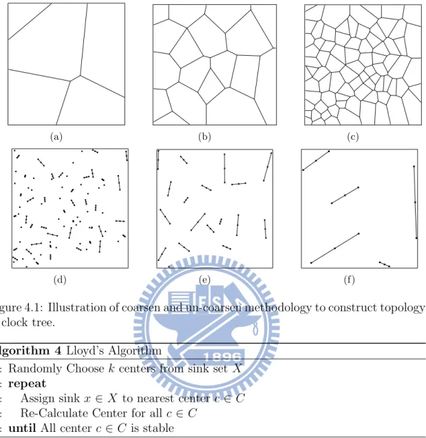
Figure 4.1: Illustration of coarsen and un-coarsen methodology to construct topology of clock tree.
Algorithm 4 Lloyd’s Algorithm
1: Randomly Choose k centers from sink set X
2: repeat
3: Assign sink x ∈ X to nearest center c ∈ C
4: Re-Calculate Center for all c ∈ C
5: until All center c ∈ C is stable
Both NNS and k-means clustering maintains k centers that forms Delaunay Triangle in each iteration. Fig.4.1(a), 4.1(b) and 4.1(c) illustrates the Voronoi Diagram for each cluster center during un-coarsening phase. Fig.4.1(d), 4.1(e) and 4.1(f) illustrates the construction of clock tree during coarsening phase. Once the topology of clock tree is constructed, Deferred Merge Embedding (DME) [7] for zero skew minimization using Elmore Delay model is implemented.
The problem of clustering can be defined as follows. Given a set of sinks X = {x1...xn}, divide the given sinks into k clusters (k ≤ n) and select k centers C =
{c1...ck} to minimize the following potential function.
φ= X x∈X min c∈C kx − ck 2 (4.1)
4.1.1
Lloyd’s algorithm
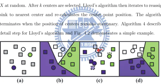
The concept of k-means clustering was originally proposed by [12], also known as Lloyd’s algorithm. Lloyd’s algorithm begins by selecting k centers from given sinks Xat random. After k centers are selected, Lloyd’s algorithm then iterates to reassign sink to nearest center and re-calculates the center point position. The algorithm terminates when the position of centers remains stationary. Algorithm 4 describes detail step for Lloyd’s algorithm and Fig. 4.2 demonstrates a simple example.
Figure 4.2: An example of k-means algorithm. (a) Randomly select 3 means which are shown in circle. (b) Assign sinks to the nearest means. (c) New centroid of each cluster are generated. (d) All sinks are reassigned to the new means, and the partitions which are generated by 3 means represent the Voronoi Diagram.
Although Lloyd’s algorithm is able to quickly identify k independent clusters, Lloyd’s algorithm suffers deficiency such that it easily resorts to local optimal so-lution. In this regard, an improved k-means clustering is implemented based on [2].
4.2
Improved k-means clustering
In Lloyd’s algorithm, the selection for initial center dominates the quality of entire cluster and Lloyd’s algorithm is susceptible to select centers that are close to each other. It is desirable to choose centers that are evenly separated from each other. Thus, [2] modifies the procedure to select centers at initial phase.
Let D(x) be the shortest distance between a sink x and the nearest center c. The improved k-means clustering randomly selects one sink as first center, and rest of k−1 centers is selected based on probability proportional D(x)2. Each time a center
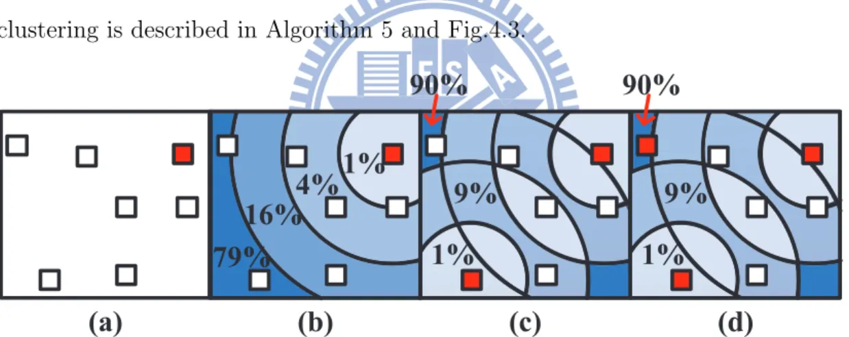
is selected, D(x) will be updated for all sink x. Thus, sinks located farthest away from all centers will have higher probability being selected. The improved k-means clustering is described in Algorithm 5 and Fig.4.3.
Figure 4.3: The first phase of improved k-means clustering. (a) The first center shown in colored square is randomly selected. (b) Calculate each sink probability with respect to the first center. (c) Select the sink with highest probability to be the second center. (d) Calculate probability with respect to both centers, then decide the third center.
Randomness in clustering offers approximation guarantee [2] and enables user to re-run the algorithm to get the best clustering. According to [2], the improved k-means clustering has an upper bound error O(logk) which guarantees the quality of the cluster.
Algorithm 5 Improved Lloyd’s Algorithm
1: Randomly Choose one center from sink set X
2: for 1 to k − 1 do
3: for each sink x ∈ X do 4: calculate D(xi)
5: end for
6: Random choose y between 0 and Pi∈nD(xi)2
7: Find i such that Pi0D(xj)2 ≥ y¿
Pi−1
0 D(xj−1)2
8: Add xi to C
9: end for
10: repeat
11: Assign sink x ∈ X to nearest center c ∈ C
12: Re-Calculate Center for all c ∈ C
Chapter 5
Interleaving clock tree generation
with flip-flop merging
This section will describe how flip-flop merging in Chapter 3 interleaves with clock tree synthesis in Chapter 4. In a nutshell, the result generated by improved k-means clustering will affect the merging priority in flip-flop merging and result produced by flip-flop merging will feed back to clock tree synthesis which will iterate until sink position is stable. When sink position is stable, clock tree synthesis will be initiated to complete the clock tree based on reduced number of sinks.
Figure 5.1: The effect of CTS due to selection of flip-flop merge. (a) is the original sink distribution (b) consructs the graph in FF-Merge (c) is an example of sink distribution with uneven load and (d) is an example of sink distribution with even load.
The objective of flip-flop merging is to maximize every possible merge. However, greedily merging flip-flop that maximizes utilization of multi-bit flip-flop may neglect quality of clock tree at global scale. Fig.5.1 illustrates such phenomenon. Assuming
all sinks have equivalent capacitance load. Fig.5.1(b) merges four sinks in the center. However, the unbalanced load will result in the additional wirelength in four corner sinks due to wire snaking for skew minimization. On the other hand, Fig. 5.1(c) that merges four sinks in the corner is a much more desirable sink topology for clock tree synthesis.
Thus, the global quality of cluster is essential to clock tree synthesis. Greedy flip-flop merging is prone to produce undesirable result that requires additional wire snaking to minimize skew. In addition, the relocation position of merged flip-flop will also affect the quality of clock tree. In flip-flop merging, merged flip-flop only needs to be placed in position that does not violate slack constraint. However, in scope of clock tree synthesis, sink position is preferably to place in position that requires less wire snaking. Viewed in this light, when determining the relocation position of the merged flip-flops, the merging point produced by clock tree synthesis should also be taken into consideration.
5.1
Interleaving procedure
Fig.5.2 demonstrates a simple example that interleaves clock tree synthesis with flip-flop merging. To begin with, in Fig.5.2(b),(c), flip-flop merging will first process the input sinks and construct overlapping graph using line sweep method described in Section 3.1. After graph is constructed, in Fig.5.2(d), the un-coarsening phase of clock tree will be initiated to iteratively un-coarsen the given sinks until each cluster have two or less sinks. The un-coarsened cluster will then select clusters with two sinks and check whether the contained sinks have corresponding edge in graph constructed during flip-flop merging. If a corresponding edge is found, it represents that not only both sinks is mergeable in flip-flop merging, it is also preferably to be merged in clock tree.
Figure 5.2: An example of interleaving CTS and FF-Merge. (b) draws out the slack-TRR of all FF. (c) constructs graph according to slack-TRR in (b). (d) performs the un-coarsening phase in CTS. (e) updates the edge cost (f) performs one iteration of FF-Merge. (g) performs un-coarsening phase in CTS one more time. (h) constructs the clock tree based on DME.
If a corresponding edge is found, the edge is then updated with a cost propor-tional to the distance between two sinks allowing the edge to gain higher merging priority which is illustrated in Fig. 5.2(e). The merging segment of the parent sink calculated during clock tree synthesis will also feed to flip-flop merging. When merg-ing two flip-flops, it will check whether there is a preferred mergmerg-ing point that is desirable to clock tree. If there exists a preferred merging point, the corresponding edge will be updated with a new cost.
In Fig. 5.2(f), when all of the edges are updated, one iteration of flip-flop merging will then be performed. In each iteration of flip-flop merging, sinks can only be merged once. The reduced number of sinks then becomes the next sink distribution for next clock tree synthesis iteration. The process iterates until sink number can not be further reduced. When sink number remains unchanged during flip-flop merging, clock tree synthesis is then initiated to complete the clock tree which corresponds
to Fig. 5.2(h).
The proposed interleaving mechanism allows flip-flop merge and clock tree syn-thesis to cope with one another. Regarding previous work on post placement flip-flop merging [14][8][3] which all focused on maximizing flip-flip-flop merge and failed to consider the characteristic of clock tree. In this work, agglomerative clustering is implemented in flip-flop merging which focuses on wirelength minimization and k-means clustering considers the general clock tree topology during clock tree syn-thesis, the clustering characteristic allows both methods to collaborate in coherent congruency.
Chapter 6
Experimental results
In this thesis, we compare our algorithm with [3], [14] and [8]. Six testcases(C1∼C6) are obtained from [3] which are also input benchmark for [14] and [8].
We obtained all of the binary executables from [3], [14] and [8]. Executables from [14], [8] and our algorithm are performed under Intel Xeon CPU 5160 Cent OS workstation running at 3.0 GHz. Executable from [3] is performed under Intel Core i3 CPU 550 Ubuntu workstation running at 3.2 GHz since it is compiled with g++ 4.5.4.
An evaluator is implemented to evaluate the flip-flop’s power and signal wire-length reduction before and after flip-flop merging and examine whether if any of the given constraints are violated. The evaluated results for all of the obtained executables are verified with corresponding authors.
To examine clock tree power consumption, flip-flop merging result for all the executable is converted to 2010 ISPD clock tree format. We then used our imple-mentation to perform final clock tree synthesis for all of the executables using exact same parameter. Final clock tree result is evaluated using script released by 2010 ISPD Clock Tree Contest with NGSPICE.
In this chapter, we present our experimental result in 2 sections. Section 6.1 will compare the detail of flip-flop merging result for all of the obtained executables by
(a) (b) (c)
(d) (e) (f)
Figure 6.1: Illustration of the flip-flop merging result on testcase C3. (a) Original case(b) Result of [8](c) Result of [14](d) Result of [3](e) Result of Our work without interleaving(f) Result of Our work with interleaving
analyzing flip-flop number reduction, flip-flop’s signal wirelength minimization and average displacement of flip-flop. Section 6.2 will present the detail of clock tree by presenting sink, buffer and clock tree wirelength capacitance for all of testcases.
6.1
Flip-Flop’s Power and Signal Wirelength
Re-duction
Table 6.1 presents the result of flip-flop number reduction. Compared with original benchmark without flip-flop merging, our algorithm can reduce flip-flop number by 65.66%. In comparison with [3] and [14], our proposed algorithm outperforms by 2.99% and 1.66% respectively. In comparison with [8], our algorithm trails behind by 2.99%. Figure 6.1 shows the flip-flop merging result of each algorithm.
Flip-flop number reduction in Table 6.1 is translated to flip-flop power reduction which is describe in Table 6.2. The detail of the given multi-bit flip-flop library is described in Table 2.1. Higher-bit flip-flop have the advantage of lower power
consumption and lower area per bit.
In Table 6.2, it can be observed that [8] achieves best flip-flop power reduction since it has fewest number of flip-flops. However, regarding to total signal wirelength connecting to each flip-flop, [8] increases most signal wirelength in all 6 testcases. In contrast, our algorithm trails behind [8] by 1.8% in terms of flip-flop power reduction but outperforms [8] by nearly 16% in terms of flip-flop’s signal wirelength. Addional increase signal wirelength implies that flip-flop’s power reduction will be counteract by increase in dynamic power consumption in signal wirelength. According to our analysis in 45nm design with 0.0002fC/nm, our algorithm in on par with [8] in terms total power consumption if average switching activity factor is 0.1 and outperforms it if switching activity is higher.
In addition to analyzing flip-flop’s power and signal wirelength, we also analyze average displacement of each merged flip-flop. Table 6.3 presents the result of aver-age displacement of merged flip-flops for all of the obtained executables. For each merged flip-flop, we can identify which of the original flip-flops it consists. Then displacement between flip-flop’s original location and its final relocation position can be calculated. In all 6 testcases, original flip-flop is given in 1-bit or 2-bit, we perform analysis on all of the testcases for each executable and present the result by taking the average displacement for 1-bit and 2-bit flip-flop.
The benefit of merging nearest neighbor flip-flops is two fold, it increases least signal wirelength and creates least peturbation to original layout. Regarding to Table 6.3, our algorithm have the least displacement with better flip-flop reduction comparing to [3] and [14]. Regarding to [8], since it have the most flip-flop reduction, it also creates most peturbation to original placement.
6.2
Result of Clock Tree Synthesis After
Flip-Flop Merging
Table 6.4 depicts the clock tree synthesis result of sink, buffer, and wire capacitance. We apply a DME-based two-stage buffered clock tree synthesis to verify the obtained results of four algorithms, and the capacitance data is obtained from NGSPICE[1]. Compared with [8], [14], [3], and our results without interleaving technique, 3.68%, 4.96% and 2.51% additional total capacitance are obtained. However, our work with interleaving technique has 2.58% less total capacitance compared with [8]. Although [8] obtains the best flip-flop reduction rate, the distant merged flip-flops cause longer clock tree wirelength. In interleaving technique, k-means clustering tends to concentrate flip-flop merging in each cluster, and reduce clock tree wirlength at the same time.
Table 6.1: Comparison on Flip-Flop Number Reduction and Detail of Multi-Bit Flip-Flop For Each Testcase
Circuit Testcase C1 C2 C3 C4 C5 C6 Total Reduction Norm. Original # of FFs (1,2,4 bits) 76,22,0 366,57,0 1464,228,0 4378,751,0 9150,1425,0 146400,22800,0 - -Total Sink# 98 423 1692 5128 10575 169200 187116 100% [8] # of FFs (1,2,4 bits) 0,4,28 0,6,117 0,14,473 2,21,1459 2,33,2983 18,113,47939 - -Total Sink# 32 123 487 1482 3018 48070 53212 29.40% [14] # of FFs (1,2,4 bits) 6,7,25 16,30,101 70,125,400 232,402,1211 484,806,2476 7580,13508,39351 - -Total Sink# 38 147 595 1845 3766 60439 66830 36.00% [3] # of FFs (1,2,4 bits) 8,10,23 24,36,96 84,146,386 242,469,1175 480,920,2420 7320,14780,38780 - -Total Sink# 41 156 616 1886 3820 60880 67399 37.33% Our # of FFs (1,2,4 bits) 2,9,25 8,36,100 28,142,402 80,450,1225 160,880,2520 2440,14020,40380 - -Total Sink# 36 144 572 1755 3560 56840 62907 34.34% 30
Table 6.2: Comparison on Flip-Flop’s Power Reduction, Flip-Flop’s Signal Wirelength and Execution Time
Circuit Original [8] [14] [3] Our
# WL(nm) PW WL(nm) PW sec. WL(nm) PW sec. WL(nm) PW sec. WL(nm) PW sec. C1 8942500 11384 8606500 9424 0 8215500 9604 0 8196500 9696 0.01 8112500 9548 0 C2 34892000 46404 35495000 37356 0 31017000 38272 0.06 33032000 38544 0.03 30534000 38192 0.02 C3 139568000 185616 144232000 149984 0.04 123585000 153300 0.29 132321000 153944 0.07 122790000 152648 0.13 C4 429065500 566972 445319500 459020 0.11 379692500 470176 0.79 405594500 471468 0.2 379287500 467600 0.5 C5 872300000 1160100 911912000 936572 0.25 755695000 959544 1.95 827580000 961280 0.49 769890000 953600 1 C6 13956800000 18561600 14654546000 14978204 3.31 12309247000 15358888 36.45 13245195000 15373520 92.64 12338170000 15254000 21.86 Norm. 1.130 1.233 1.157 1 1 1.002 1.023 11.012 1.065 1.028 27.988 1 1.018 6.604 31
Table 6.3: Comparison on Average Displacement Distance of Merged Flip-Flops
Circuit [8] [14] [3] Our
Testcase 1-bit(nm) 2-bit(nm) 1-bit(nm) 2-bit(nm) 1-bit(nm) 2-bit(nm) 1-bit(nm) 2-bit(nm)
C1 37658 49309 41875 19500 41426 22333 38270 19477 C2 40208 47922 38999 19760 38827 21350 36989 18907 C3 40717 48353 39820 19761 38399 21121 37222 18907 C4 41044 48129 40006 20361 38363 21098 37433 19041 C5 41027 48662 39429 20155 38159 21090 37362 18907 C6 41021 48898 39810 20395 38047 21103 37430 18907 Avg. 40279 48546 39990 19989 38870 21349 37451 19027
Table 6.4: Comparison on Clock Tree Synthesis Results including Sink, Buffer and Wire Capacitors after Multi-Bit Flip-Flop Construction among [8], [14], [3], and Our Work with and without Interleaving Technique
Circuit Testcase c1(fF) c2(fF) c3(fF) c4(fF) c5(fF) Norm.
Original Skew 0.2 1.586 2.104 2.069 2.86 -Sink 398.44 1624.14 6496.56 19844.02 40603.5 -Buffer 485.8 1927.8 7036.6 31911.1 65983.5 -Wire 586.426 2604.8 10873.25 34426.621 70841.548 -Total 1470.666 6156.74 24406.41 86181.741 177428.548 1.556 [8] Skew 0.408 0.49 0.992 2.063 1.997 -Sink 327.32 1313.76 5249.44 16065.7 32780.02 -Buffer 485.8 1763 6377.4 14699.8 38431 -Wire 397.587 1608.361 6655.228 20600.921 42801.949 -Total 1210.707 4685.121 18282.068 51366.421 114012.969 1 [14] Skew 0.252 1.145 0.87 2.834 1.829 -Sink 336.14 1339.52 5365.5 16456.16 33584 -Buffer 485.8 1763 6377.4 16183 39883.3 -Wire 380.335 1788.71 7310.818 21835.078 45611.517 -Total 1202.275 4891.23 19053.718 54474.238 119078.817 1.037 [3] Skew 0.037 0.824 0.681 2.796 1.967 -Sink 339.36 1349.04 5388.04 16501.38 33644.8 -Buffer 485.8 1763 6377.4 16183 39749.4 -Wire 399.274 1793.078 7455.872 22734.639 47450.315 -Total 1224.434 4905.118 19221.312 55419.019 120844.515 1.050
Our work without interleaving
Skew 0.015 1.097 0.716 2.407 1.658
-Sink 334.18 1336.72 5342.68 16366 33376
-Buffer 485.8 1763 6377.4 15523.8 39749.4
-Wire 382.901 1716.058 7079.658 21492.976 45051.305
-Total 1202.881 4815.778 18799.738 53382.776 118176.705 1.025
Our work with interleaving
Skew 0.297 0.662 2.392 2.324 2.024
-Sink 334.18 1341.2 5357.24 16392.88 33440
-Buffer 485.8 1763 4811.8 14123 39749
-Wire 346.219 1557.159 6342.141 20601.14 42482.96
Chapter 7
Conclusions
In this thesis, a co-synthesis method on clustering based flip-flop merging and clock tree synthesis is presented. According to observation, the proposed flip-flop merging can achieve roughly 60% in sink reduction. When interleaving with clock tree syn-thesis, it can reduce total clock tree wirelength by 33% by selecting optimal position for merged flip-flop. Agglomerative clustering shares common principle as Nearest Neighbor Selection which guarantees lowest cost to merge all nodes.
In addition to flip-flop merging, we also propose a two-phase clock tree synthesis based on improved k-means clustering. The selection of initial center based on [2] guarantees that the result error is bounded. Similar to Nearest Neighbor Selection, a Delaunay triangulation is maintained in each iteration of clock tree topology con-struction. Such approach will focus on topology of clock tree while taking wirelength minimization into consideration. In this regard, agglomerative clustering focus on local wirelength minimization and K-Means clustering considers global clock tree topology making both algorithms mutually complement to one another.
Bibliography
[1] NGSPICE. http://ngspice.sourceforge.net/.
[2] D. Arthur and S. Vassilvitskii. k-means++: The advantages of careful seeding. In Proceedings of the ACM-SIAM Symposium on Discrete Algorithms, pages 1027–1035, 2007.
[3] Y.-T. Chang, C.-C. Hsu, M. P.-H. Lin, Y.-W. Tsai, and S.-F. Chen. Post-placement power optimization with multi-bit flip-flops. In IEEE/ACM Inter-national Conference on Computer-Aided Design, 2010.
[4] L. Chen, A. Hung, H.-M. Chen, E. Tsai, S.-H. Chen, M.-H. Ku, and C.-C. Chen. Using multi-bit flip-flop for clock power saving by designcompiler. In Proceeding Synopsys User Group, 2010.
[5] J. Cong, A. B. Kahng, C.-K. Koh, and C.-W. A. Tsao. Bounded-skew clock and steiner routing. ACM Transaction Design Automation Electronic System, 3(3):341–388, 1998.
[6] T. H. Cormen, C. E. Leiserson, R. L. Rivest, and C. Stein. Introduction to Algorithms. MIT Press, 2001.
[7] M. Edahiro. A clustering-based optimization algorithm in zero-skew routings. In Proceedings of the International Design Automation Conference, pages 612– 616, 1993.
[8] I. H.-R. Jiang, C.-L. Chang, Y.-M. Yang, E. Y.-W. Tsai, and L. S.-F. Chen. INTEGRA: fast multi-bit flip-flop clustering for clock power saving based on interval graphs. In Proceedings of the International Symposium on Physical Design, pages 115–121, 2011.
[9] M.-C. Kim, D.-J. Lee, and I. Markov. SimPL: An effective placement algo-rithm. In IEEE/ACM International Conference on Computer-Aided Design, pages 649–656, 2010.
[10] D. Lee and I. Markov. Contango: Integrated optimization of SoC clock net-works. In Design Automation Test in Europe Conference Exhibition, pages 1468–1473, 2010.
[11] D.-J. Lee and I. L. Markov. Obstacle-aware clock-tree shaping during place-ment. In Proceedings of the International Symposium on Physical Design, pages 124–130, 2011.
[12] S. Lloyd. Least squares quantization in PCM. IEEE Transactions on Informa-tion Theory, 28(2):129–137, 1982.
[13] C. N. Sze. ISPD 2010 high performance clock network synthesis contest: bench-mark suite and results. In Proceedings of the International Symposium on Phys-ical Design, 2010.
[14] S.-H. Wang, Y.-Y. Liang, T.-Y. Kuo, and W.-K. Mak. Power-driven flip-flop merging and relocation. In Proceedings of the International Symposium on Physical Design, pages 107–114, 2011.