國
立
交
通
大
學
電機學院 IC 設計產業研發碩士班
碩
士
論
文
無線通訊中涵蓋跨層級多節點之媒體擷取控制層的
軟硬體協同設計平台
Platform Based Cross-Layer Multi-node MAC
Hardware/Software Co-design
for Wireless Communication System
研 究 生:施俊宇
指導教授:黃經堯 博士
無線通訊中涵蓋跨層級多節點之媒體擷取控制層的
軟硬體協同設計平台
Platform Based Cross-Layer Multi-node MAC
Hardware/Software Co-design
for Wireless Communication System
研 究 生:施俊宇 Student:Chun-Yu Shih
指導教授:黃經堯 Advisor:Ching-Yao Huang
國 立 交 通 大 學
電機學院 IC 設計產業研發碩士班
碩 士 論 文
A ThesisSubmitted to College of Electrical and Computer Engineering National Chiao Tung University
in partial Fulfillment of the Requirements for the Degree of
Master in
Industrial Technology R & D Master Program on IC Design
June 2006
Hsinchu, Taiwan, Republic of China
無線通訊中涵蓋跨層級多節點之媒體擷取控制層的
軟硬體協同設計平台
學生:施俊宇
指導教授
:黃經堯博士
國立交通大學電機學院產業研發碩士班
摘
要
本論文研製之由於在一個無線通訊的系統晶片驗證是不可或缺的工作,但在
無線通訊裡必須考慮非本身的因素而導致不能早期達到理想的驗證成果,尤其是
在系統晶片設計的高度複雜性與產品推入市場的時間壓力下,如何在驗證流程的
早期做到完善的驗證是個關鍵。在這篇論文裡使用了結合多項功能的系統層級設
計工具,它提供軟硬體共同設計、系統架構分析、共同驗證,以此為基礎來把層
級推向更高於系統層級的方向來建構符合無線通訊系統的環境,將可在早期驗證
流程中提供一個能銜接資源管理和接取技術控制演算法與系統效能分析之間關
係更精確與方便的模擬平台。
Platform Based Cross-Layer Multi-node MAC Hardware/Software
Co-design for Wireless Communication System
student:Chun-Yu Shih
Advisors:Dr.
ChingYao Huang
Industrial Technology R & D Master Program of
Electrical and Computer Engineering College
National Chiao Tung University
ABSTRACT
A procedure is for SoC verification process in wireless communication
system. The most concern in wireless communication system is interactive
between base stations and mobile stations. In other words, this is not enough
for SoC verification to verify a single base station or mobile station,
especially under the pressure of time-to-market and design complexity.
Therefore, how to verify the interactive of wireless communication system
fast and completely in the early process of design flow is the key point. This
paper introduces an ESL tool, including HW/SW co-design, system
architecture exploit, and co-simulation/verification, to establish a cross-layer
multi-node environment for verifying the interactive and analyzing the system
performance. The fundamental design concept is a system level design
abstraction, so it can conveniently provide precise analysis results of a system
performance in the early process of design flow.
誌謝
首先, 我要感謝我的家人, 在我求學的這段過程中, 沒有他們的全力支持,
我無法順利完成學業。也要感謝我的指導老師黃經堯教授, 提供我正確的
方向與做法並用心指導我的論文, 使我在這兩年的學習過程受惠良多。
還要感謝實驗室的伙伴, 在研究過程裡,提供許多幫忙與意見, 而實驗室
的親切與融洽的氣氛, 讓在外地求學的我感到濃濃的家鄉味, 每每都能
讓我作研究時有充電再續航的能力。最後要感謝我的女友佩儀與小成員
猪猪,為我的生活增添許許多多的色彩與美好回憶, 尤其是女友八年來在
我背後默默地關心、照顧與支持, 更是我能朝理想邁進的一大推手。
霧黃映柳
沒有風的伴隨
即將落地的羽
如何能譜出一曲
動人的月舞
獻給她
施俊宇 謹致
Contents
Abstract (in Chinese)………..I Abstract (in Chinese)………..II Acknowledgement (in Chinese)……….III Contents……….. IV Figures……….V Tables………...………VI
I. Introduction………1
II. Architecture for cross-layer multi-node simulator………..5
III. Design and Implementation of a cross-layer multi-node simulator based on ESL verification platform……….7
A. Platform design……….8
B. Architecture design………..10
IV. Hardware/Software Co-design……….………..12
A. Design tool and design flow………..12
B. Mobile Wimax Overview………..….16
C. Proposal MAC layer architecture………..…...25
1. Data plane implementation……….……..…….25
2. Control plane implementation………..………26
3. Algorithm development……….…………26
4. Performance analysis……….……….…. 30
5. Partition and co-verification……….………31
V. Conclusion and future work……….………….……….34
Figures
Figure 1 Different kinds of design viewpoints ………3
Figure 2 Architecture of the cross-layer multi-node simulator…….……….5
Figure 3a Platform design of the cross-layer multi-node simulator…..….………...8
Figure 3b Platform design on ARM SOC Designer……….………...9
Figure 4 Control flow and data flow for downlink transmission………..11
Figure 5 Control flow and data flow for uplink transmission……….…..11
Figure 6 Platform based design flow………..….13
Figure 7 Proposal platform architecture………..……..15
Figure 8a Mobile Wimax……….…………...………..16
Figure 8b Wireless link with adaptive modulation and coding scheme………...…19
Figure 8c Transmission modes in the IEEE 802.16 standard……….……..19
Figure 8d Processing units as MAC and PHY………..…….20
Figure 8e Time plane of IEEE 802.16 frame structure……….……21
Figure 9 Proposed MAC architecture……….24
Figure 10 Standard interface in control plane………..….………27
Figure 11 Packet loss rate……….………...…28
Figure 12a MS side Handover state diagram……….…29
Figure 12b BS side Handover state diagram……….……….30
Figure 13 Data plane hardware block diagram………..………...32
Tables
Table1 Profiling results for main functional blocks of BS side………..31 Table 2 Hardware/software co-work profiling………33
I. Introduction
In wireless communication technology, Medium Access Control (MAC) protocols take an important role in coordinator between multi-nodes interactions, such as Base Stations’ (BSs) communicating with Mobile Stations (MSs). From a implementing viewpoint, a MAC layer can be separated to data plan and control plan[1][2]. The data plan is responsible for forming MAC Protocol Data Units (PDUs), and can be easily validated and analyzed by using FPGA and ESL methodology[3]. The control plan is taking control of data plan depending on various information including physical (PHY) layer’s, upper layer’s and other stations’ responses. The last factor is the most important to considerate, and is difficult to validate and analysis in the early stage of the System-on-Chip (SoC) design process. For example, in wireless communication technology the operations of data transmission of MAC layer includes request/grant mechanism that is an interaction between BS and MS. The content of transmission data sending for request by MS must be recognized by BS, and via versa. Besides, in MAC layer, there are several wireless communication mechanisms, such as Automatic Repeat Request (ARQ), handover, uplink scheduling, and etc. Those operations, triggering by the responses of other stations and channel condition outside the system environment, always effect system performance. This multi-node design abstraction in the wireless communication system is beyond the system-level and hard to be validated early. In other words, a verification procedure for the functionalities in the control plane of MAC layer is always started at the latest stage of the design process.
In recent years, general approaches to implement MAC layer are based on embedded processor[3][4]. It is an approach to use an embedded system with IP modules to quantitatively analyze workload and to verify hardware accelerators based on HW/SW co-design methodology. But in embedded system a MAC layer is difficultly analyzed some
workload, such as ARQ and uplink scheduling, and etc. In the meantime, because of implementation complexity, long time to debug, it will lost fast development process[5]. It means that the MAC layer needs a multi-node environment for analyzing workload on embedded system. At the same time, reducing the design complexity and time-to-market pressure, we need a new way to improve the quality of the analysis in the early stage of design process.
A MAC algorithm designer takes care of various factors to valid his algorithm in the wireless environment established by MATLAB or C/C++ language. It is necessary to estimate various situations with the information from channel condition and different layers and stations. But a having validated algorithm has no analysis results form the performance of the integrated system which needs to consider any impact in integrated system specifications. Therefore, different kinds of design viewpoints lead to a gap between MAC algorithm designer and integrated system designer in the early stage of the design process, as shown in Fig.1. It means that the impact on the integrated system performance is known only when a real chip comes out.
Fig.1 Different kinds of design viewpoints
Designing an integrated system always consumes a large amount of effort and time. It is important to efficiently and completely set up a system during the design process. Because of those reasons, we believe that if one simulation environment has all kind of information for MAC algorithm designers and help them to look inside the integrated system. Then, it
can eliminate the gap and provide more considerations to avoid the performance loss within the design and implementation budget of the integrated system. Besides, it could reduce the time-to-market pressure and design complexity when the verification process and performance evaluation are both started in early stage of the design process.
In this paper, we proposed the cross-layer multi-node simulator for the MAC layer design, based on ESL verification platform, is established for evaluating the performance of the MAC layer design. The focus is the design procedure of the multi-node environment with ARM-based processors on ESL verification platform. We will also present the implementation of the MAC layer of the Mobile Wimax on MS side, and validate the design by using our simulator. At final, we discuss some benefits in our simulator design if this new technology with ESL methodology is available in the early stage of the design process.
The remaining paper is organized as follows: In Section II, the verification platform and architecture design for our cross-layer multi-node simulator are described. Section III and IV includes the hardware/software co-design and simulation results on the MS side. Finally, the conclusions are drawn in Section V.
II. Architecture for Cross-layer multi-node simulator
Fig.2 Architecture of the cross-layer multi-node simulator
To provide a simulation environment for evaluating the performance of the MAC layer design, we propose the architecture for cross-layer multi-node simulator based on ESL methodology, as shown in Fig.2. The ESL design methodology using systemC technology can help engineers valid and analyze their design with architecture exploit, HW/SW co-design, and co-simulation/verification in the early stage of design process. It is possible for us to design a simulator, based on ESL verification platform, with modeling the multi-node interaction and to provide various kind of information for MAC layer design. At the upper layer, the process is responsible for forming Service data Units (SDU). For increasing the quality of the verification at an integrated system design, it can be ported with an embedded real-time operation system.
At the MAC layer, the process can be separated to data plane and control plane. The data plane is responsible for forming MAC protocol data unit. And the control plane is taking control of data plane with various information and situation between the lower and upper layer. This control plane can be separated in downlink control and uplink control. The
downlink is from BS to MS on a point-to-multipoint connection. The uplink is shared by all of MSs from MS to BS on a demand. To improve the performance of wireless communication, MAC must make a good decision on various kinds of information from different layer under the specific time basis. Therefore, the MAC layer always takes important role in the wireless communication system. And we will focus on it for the rest of this paper.
At the lower layer, the processing unit is a frame which consists of multiple transmission symbols with transmission modes which resist the effect on time-vary channel condition. The data is transmitted frame by frame with a fixed number of symbols using Modulation and Coding Scheme (MCS) based on channel estimation. With the MCS adaptively, the bandwidth utilization can be accomplished efficiently for a Packet Error Rate (PER) performance.
III. Design and Implementation of the Cross-Layer Multi-Node
Simulator based on the ESL verification platform
Since the late 1980s, the design abstraction has remained at RTL level. Under the pressure of time-to-market and the design complexity which has become increasingly unmanageable, ESL is a new validation technology and methodology. It is driven by choosing a set of the re-use hardware modeling components from the platform library, and can be flexible to support different applications. This approach enables hardware/software co-design in the early stage of design process. However, available for most of domain designs, ESL technology is still not enough to address the validation and performance analysis for multi-node interaction, such as BSs’ communicating with MSs in wireless communication environment, especially MAC layer taking an important role in coordinator between other stations. Therefore, we focus on multi-node system instead of a single system on ESL verification platform.
A. Platform-based design:
Fig.3a. Platform design of the cross-layer multi-node simulator
Raising the MAC layer verification process based ESL methodology to early stage for the specific system requirements in a wireless communication system, every single integrated system contains a processor, memory system, peripherals and etc. Those are used the hardware modeling technology with systemC. Meanwhile, every integrated system connects with a central system for an interaction of the wireless-like data transmission from one station to another, as shown in Fig.3a.
Here, we present the connecting of every single integrated system on ESL verification platform. To connect every single integrated system, we allow different processor with a bus in each system to access the same address region of the “share memory”. From the viewpoint of embedded system it means that BS can storage the information data in “share memory” when BS wants to transmit information to MS. After that, MS can access the same address region of the “share memory” in specific time basis. In the mean time, the
channel integrated system is responsible for taking care of BS and MS in when to access the “share memory”, and behaving as a nature environment for the evaluation and verification of the MAC layer. To precisely evaluate and verify the system performance for a single system such as BS or MS, it is clearly defined the application which is needed in each system. For example, the MAC layer should be implemented in both BS and MS system, but not in the channel system. And the channel model must be ported in the channel system.
So, we can model the data transmission and have the benefits of the functionality verification and performance analysis of the MAC layer for the specific system requirements in the early stage of the design process. The Fig.3b shows our platform design implemented on ARM SOC Designer.
B. Architecture design:
In the architecture design of the BS or MS side, it can be implemented with the upper layer, MAC layer, and lower layer which are executable programs loaded in ARM-based processor. The sensor function is implemented to detect the specific control information within the “share memory” of the channel system. The upper layer takes a response for forming the Service Data Units (SDUs) then sending the SDUs to the MAC layer buffer. The lower layer is responsible for forming a symbol with AMC which is to maximize the transmission rate by adjusting its transmission modes with a QoS algorithm to maintain the PER at the time-vary channel condition[9][18].
In the channel system, the “share memory” is defined to save the common control information for the connecting of each system, and a set of the subchannel-like area for saving the transmitted data from each BS or SS. The multi-user interface is used to support the Carrier Sense Multiple Access (CSMA) mechanism in the uplink transmission. To more clearly evaluate the performance for each system, BS or MS, the channel system can be implemented to be a central controller for synchronizing and communicating with each station and to provide the specific functionalities which are mobility, time-vary channel model and etc. In other words, those specific functionalities do not exist in any real system but necessary for the MAC layer evaluation, such as channel model, mobility and etc.
Different instinct of transmitting information in the downlink and uplink technology, we design different data and control flows for downlink (sharing channels operation with time-division) and uplink (contenting channels), as shown in Fig.4 and Fig.5.
Fig.4 Control flow and data flow for downlink transmission
IV.
Hardware/Software Co-design
A. Design Tool and Design Flow
We implement 802.16-2005 MAC layer in a manner based on ESL (Electronic System Level) Design. A complete design progress starts from defining or understanding system specification, based on this, we can have an architecture containing functional blocks with control and data signal flow. Then we implement the system with both hardware and software and then verify the design at final. The proposed design flow is described in Fig. 6 and will be explained as follows:
Fig.6 Platform Based Design Flow
Since 802.16-2005 MAC has vary-size memory access and indefinite amount of data processing, therefore, it is more preferred to implement the system with pure software from
the start. Algorithm development and layer interface issues are handled at this stage. We apply profiling using software IDE in order to gain a rough insight of system performance, and then considering the cross-layer co-simulation in order to ensure the correctness of functional behaviors.
After software development, to accelerate the processing speed, substitution of bottleneck functional blocks with HW implementation is a necessary choice. The data plane, especially the part dealing with SDUs, contains computational operations that is routine and repeated, and is therefore more favorable for HW substitution. The control plane, which contains less frequently called functions and each requires variable amount of memory, is less favorable.
HW/SW co-design starts with building a processor based platform. The design tool used for platform construction is the ARM RealView SoC designer. This tool has a GUI (Graphical User Interface) that is friendly to designers.
As shown in Fig.7, a processor based system platform basically includes a processor core, memories, buses, and hardware cores. All modules used in the proposed design, except the user defined hardware core, are provided by the built-in libraries of the design tool. The architecture of the platform can be defined and modified arbitrarily by users, but shall conform to certain design rules and bus protocols in order to work properly.
B.Mobile Wimax Overview
The communication technology has evolved continually for decades, and mobile video streaming becomes a popular service after the conventional voice connection. As the demand of broadband wireless access (BWA), grows rapidly, people need advanced technologies to provide high speed wireless transmission services under some constraints such as the standby time, product size, and etc. Among all cellular technologies, the WiMax standard (IEEE 802.16 2004/ 2005) is considered as one of important candidates for supporting these new services.
1. Medium access control methods:
The BWA system is a two-way point-to-multipoint wireless network. And it is a kind of shared medium. Therefore, there are several developed MAC technologies below.
(1) Duplex
This technology is developed to decide the relationship between the downlink and uplink. It includes the FDD (frequency division duplex) and TDD (time division duplex). FDD uses a pair of frequency bands for downlinks and uplinks. And TDD uses a frequency slot on a time basis.
(2) Downlink
Downlink is from BS to MSs with a point-to-multipoint operation. The BS broadcasts information to all MSs with a choose multiplexing method. Each MS will receive all information and check out what the signal is belonged to its. FDM (frequency division multiplexing) and TDM (time division multiplexing) are main multiplexing methods. FDM is for BS to send signals to MS in different frequency slot. And TDM is for BS to allocate several time slots to MS if MS has a requirement.
(3) Uplink
ALL the MS could share some uplink signals to BS who controls the uplink access. There are two kinds of uplink operations, FDMA (frequency division multiple access) and TDMA (time division multiple access). The FDMA is for BS to allocate a frequency slot to MS when MS wants to transmit signals to BS. The TDMA is for MS to transmit its
signals to BS in an allocated time slot.
(4) Combination
(i)FDMA/FDM/FDD is for fixed rate access service, but not suitable
for large number of MSs because of the limit of bandwidth utilization;
(ii)FDMA/TDM/FDD is for the high rate in the downlink and fixed rate
in the uplink, but not suitable for the flexible rate in the uplink;
(iii)TDMA/TDM/FDD (iv)TDMA/TDM/TDD
They are appropriate for high speed, flexible rate and large number of MSs.
(5) Request/grant mechanism
The bandwidth request/grant is a key method in BWA system. there are three man methods in this operation.
(i) Polling: The BS broadcasts an ID for the MS in each downlink
frame, and then the MS is the only one that can use the coming slot in next frame to transmit its bandwidth request to the BS. (ii) ALOHA: Each MS send its request randomly in a fixed
channel.
(iii) Piggybacking: on the current transmission, the MS send the
piggybacking to reduce overhead bandwidth allocation. But when the MS has no current transmission, the system must provide an additional operation to establish the first transmission by using polling or ALOHA.
2. Processing Units at MAC and PHY
We introduce all connection communicating with the BS using time-division multiplexing/time-division multiple access (TDM/TDMA). The wireless link of each connection from BS to MS is depicted in Fig.8b. At PHY, multiple transmission modes are available for each user. Those represent a pair of a specific modulation format based on channel estimation obtained form receiver, as shown in Fig.8c. The AMC selector determines the modulation-coding scheme whose index is sent back to the transmitter through a feedback channel for the AMC controller to update the transmission mode.
Fig.8b Wireless link with adaptive modulation and coding scheme
Fig.8d Processing units at MAC and PHY
At the MAC, the processing unit is a packet consisting of multiple information bits which include packet header, payload, and cyclic redundancy check (CRC) bits. At the PHY, the processing unit is a frame consisting of multiple transmission symbols. And data are transmitted frame by frame through wireless channel.
Based on channel estimation at the receiver, the adaptive modulation and coding (AMC) selector determines a suitable scheme.
After modulation and coding with appropriate transmission mode and transmission rate, each packet is mapped to a symbol block consisting of multiple symbols, as shown in Fig.8d.
3. Time Plane of 802.16e OFDMA Systems
Fig.8e Time plane of IEEE 802.16 frame structure The frame structure consists of the following:
A preamble using the first symbol, FCH with fixed number of subchannel, DL_MAP and UP_MAP message for resource allocation of downlink and uplink data bursts, and some uplink control channel for ranging, uplink ACK and etc.
DL_MAP can present resource allocation information for burst or each MS. It will cause processing overhead when MS must search its own packet among many packet combined in a burst. And however, each MS can be effectively allocated resource by using DL_MAP, it causes another overhead due to transmission of many DL_MAP IE message. Therefore, the 802.16 system defines several kinds of MAP message to reduce the size of MAP messages.
Additionally, the 802.16 system defines two kinds of subchannel establishing methods to support various types of channel condition.
4. Diversity Subchannels:
It is expected to achieve the MSs with high velocity or low signal-to-interference ratio (SINR) for avoiding deep fading and averaging intercell interference by selecting subcarriers pseudo
randomly. 5. Band AMC Subchannels:
In this channel structure, the channel response can be seen as a flat fading channel. Due to the flat fading nature of this subchannel, the system can good at the multi-user diversity as the channel situation does not significantly change during the scheduling procedure. Therefore, it is expected to appropriate for MSs with low velocity or high SINR.
The Mobile Wimax standard provides several uplink control channels for fast exchange of information, such as physical channel information and ACK/negative ACK (NACK), for cross-layer operation. And the system performance can be improved by carefully utilizing those uplink control channels to exchange cross-layer information.
1) CQICH—The channel quality information channel (CQICH) is allocated to an MS using a CQICH control IE management message, and is used to report the downlink carrier-to-interference-plus-noise ratio (CINR) for either diversity subchannels or band AMC subchannels. This channel occupies one uplink slot in the FAST-FEEDBACK region allocated through UL_MAP message. For diversity subchannels, the MS reports the average CINR of the BS preamble from which the BS is able to determine the DL modulation and coding scheme (MCS) level. Here, a CINR measurement is quantized into 32 levels and encoded into five information bits. On the other hand, for band AMC subchannels, a mobile station (MS) can report the differential of CINR values of five selected frequency bands (increment: 1 and decrement: 0 with a step of 1 dB) on this CQICH after reporting the CINR measurements of the five best bands using a MAC management message such as REP-RSP.
2) Fast Feedback Channel—Fast feedback channels may be allocated individually to MSs for the transmission of PHY-related information that requires a fast response from the MS. One fast feedback channel occupies one UL slot in the FAST-FEEDBACK region allocated through a UL_MAP message. Using these fast feedback channels, the MS can report the followings:
‧ Variable information for MAC operation, such as the anchor BS selection information for macro diversity handover and the request for UL rate adaptation
of VoIP service
‧ PHY-related information, such as DL channel measurement information for multiple-input multiple-output (MIMO )operation, the MIMO coefficient for the best DL reception (e.g., antenna weight), and MIMO mode selection (e.g., space-time transmit diversity [STTD], spatial multiplexing [SM], and beamforming).
3) UL ACK Channels—A HARQ ACK channel region for the inclusion of one or more ACK channel(s) for HARQ support of MSs is allocated using a HARQ ACK region allocation IE. The UL ACK channel occupies one half-slot in this HARQ ACK channel region, which may override the fast feedback region. This UL ACK channel is implicitly assigned to each HARQ enabled burst according to the order of the HARQ-enabled DL bursts in the DL MAP. Thus, the MS can quickly transmit ACK or NACK feedback for DL HARQ-enabled packet data using this UL ACK channel.
4) UL sounding—The 802.16e OFDMA system defines UL sounding to support smart antenna or MIMO, and this UL sounding is a kind of UL pilot signal. The BS measures the UL channel response from UL sounding waveforms transmitted by each MS, and translates the measured UL channel response to an estimated DL channel response under the assumption of TDD reciprocity. In order to allocate resources for the transmission of UL channel sounding, the BS allocates a sounding zone through a UL_MAP message. In this sounding zone each MS can transmit its UL sounding signal, maintaining signal orthogonality among multiple multiplexed MS sounding transmissions.
C. Proposal MAC Layer Architecture
In this paper, we discuss both base station (BS) and mobile station (MS) MAC common part sublayer architectures. Each of them is composed of two planes: Data Plane and Control Plane.
The data plane is responsible for forming MAC Protocol Data Units (PDUs) with incoming data or management messages. The control plane is responsible for making decisions on measurements and parameters according to algorithms, and producing parameters needed in management messages and data plane operation.
Fig.9 is our proposed BS MAC architecture. The MS has similar architecture with partially different block functions.
1. Data Plane Implementation Issues
The data plane is responsible for forming protocol data units (PDU) from data packets, i.e. service data units (SDU) coming from upper layers. The proposed architecture of MAC data plane is illustrated in the right half of Fig.9.
The main course of the data plane architecture is composed of several operations on SDUs:
a) Classification – Mapping packets to various connections according to its service flow. b) Scheduling – Arranging the transmission order among SDUs of different connections. c) Framing – Including fragmentation and packing.
d) Header – Appending headers and subheaders to payloads.
e) CRC Computation – Computing CRC field if ARQ is enabled for this connection. Another sources of PDU payloads are management messages. The decision of message parameters is in the control plane, while the data plane is responsible for accessing the parameters and turns them into PDU payloads. This takes complicated bit manipulations.
After being generated, the PDUs are concatenated, i.e. packed into data bursts according to destination.
2. Control Plane Implementation Issues
The control plane is responsible for issuing management messages and taking control of data plane operation. The proposed architecture of MAC control plane is illustrated in the left half of Fig.9.
The proposed control plane architecture is mainly composed of three parts:
a) Management Message Composer – The parameters needed in a management message is gathered by the composer, and then passed to the data plane in the form of C language structures.
easy to be added or removed.
c) Archive – All parameters are stored in the archive and subjected to access by message composer, data plane, and algorithm modules.
3. Algorithm Development Issues
To facilitate algorithm development, the algorithm functional blocks must be fully modularized and can be easily added or removed. This can be done by applying a standard interface, as illustrated in Fig.10. The standard interface comes in the form of a variable archive. Variables are declared global; can be accessed by all algorithm modules, message composer, and data plane. If necessary, new variable can be added at ease.
Fig.10 Standard Interface in Control Plane
Here we discuss development issues of two algorithms:
a) Scheduler: The scheduler determines the order of the transmission of packets destined to different users, according to some disciplines with respect to data arrival time, priority, and service quality. In this study, we consider real-time polling service, where usually an Early Deadline First (EDF) discipline is used. The goal of designing scheduler is to reduce packet loss rate. In order to explain the concept of algorithm designs, we had a simulation on the scheduler. We assume an error free channel, then a
packet would be loss only if it cannot be sent out before its deadline. The parameter settings are:
‧ Bandwidth per sector: 5MHz ‧ FFT size: 512 points
‧ downlink sub-frame / frame duration: 3 / 5ms ‧ modulation scheme: 64-QAM
‧ channel coding rate: 1/2 ‧ sector throughput: ~2Mbps
Fig.11 shows the simulation result for the packet loss rate of our proposed EDF algorithm for different number of users in a sector.
As expected, the packet loss rate will grow as the number of user increases.
b) Handover: Handover is a fundamental issue for mobile WiMAX. In the proposed design, we adopt a simple handover algorithm where the handover condition is based on two facts: 1. The neighbor BS exhibits better service quality than the serving one by a threshold value and 2. This condition lasts for a certain period of time.
In algorithm module development, handover is basically implemented with a finite state machine. Fig.12a and 12b illustrate state transitions under the scenario that the handover is initiated by the MS. The state transitions are either controlled by received service quality, message transmission/arrival, and the expiration of related timers. When the MS requests handover by transmitting MSHO-REQ, but no response is received within a timer, T41, the MS will give up the handover request and returns to the original state.
Fig.12b BS Side Handover State Diagram
4. Performance Analysis
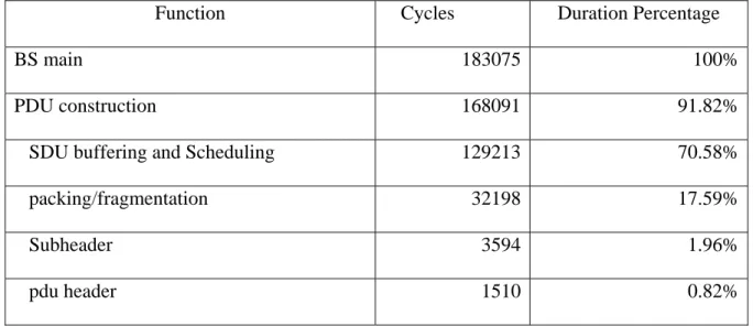
The design tool’s “Profiling” function provides a cycle-accurate performance analysis on the software along with the designer-defined platform. The heavy-loading blocks, i.e. performance bottlenecks, should be replaced with hardware implementations. Table 1 depicts the profiling results analysis of main function blocks in the BS architecture.
As predicted, the bottleneck functional blocks are located at the data plane. This is reasonable since the data plane contains parts that are frequently referred, heavily looped and complicated in computation.
Table 1: Profiling Results for Main Functional Blocks of BS
Function Cycles Duration Percentage
BS main 183075 100%
PDU construction 168091 91.82%
SDU buffering and Scheduling 129213 70.58%
packing/fragmentation 32198 17.59%
Subheader 3594 1.96%
pdu header 1510 0.82%
5. Partition and Co-verification
After the performance bottlenecks are characterized, we can partition the system into hardware and software parts. The partition rule mainly depends on the profiling results, while characteristics of individual blocks are also important. For example, hardware implementation may not be suitable for a functional block involving complicated algorithms, since it considers many parameters (conditions) and would become a large-area circuit. Another example is that timing-critical functions may be implemented as hardware in order to meet timing requirement.
Here we make the most parts of data plane, including packing, fragmentation, and header /sub-header writing as hardware models. The block diagram of data plane hardware is shown in Fig.13.
An important reason why ESL methodology facilitates the system design is that we can simulate the hardware (together with software and platform) without the completion of hardware designs. In ARM RealView SoC Designer, a hardware part can exist in the system as a model. Note that in this study, we did not implement hardware with hardware
description languages (HDL). We did it with transaction level modeling (TLM). The hardware model is written in C language, with a SystemC “wrapper” to do port mapping and identify other necessary characteristics.
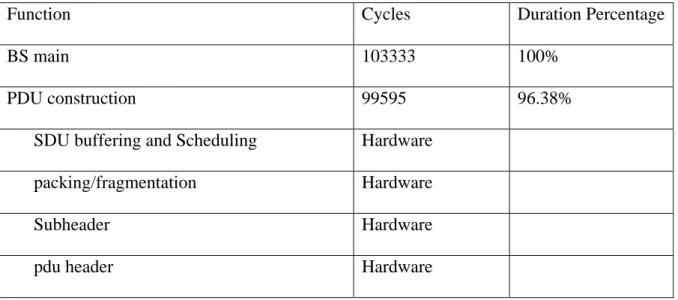
After partitioning data plane as hardware, the resulting profiling are listed in Table 2.
Table 2: HW/SW co-work profiling
Function Cycles Duration Percentage
BS main 103333 100%
PDU construction 99595 96.38%
SDU buffering and Scheduling Hardware
packing/fragmentation Hardware
Subheader Hardware
pdu header Hardware
Comparing Table 1 and 2, we see that the substitution of bottleneck functional blocks with hardware reduces the overall BS cycle number by about 43.56%.
V. Conclusions and Future Work
In this paper, for the MAC layer design, we presented a cross-layer multi-node simulator based on ESL verification platform with an example of mobile WiMax, and introduced an efficient design procedure with hardware/software partition by using our simulator. The benefit of a fast decision and verification for hardware/software partition is also presented.
Finally, we summary the feature of our simulator as fallowed.
I. Eliminate the gap between the MAC algorithm and integrated system designer:
Porting a MAC algorithm in the integrated system during the early design process can take more considerations of a system performance under the specific design requirements to avoid performance loss within design and implementation budgets.
II. Reducing design complexity and time-to-market pressure: Because of the wireless
environment with various unpredictable factors, the MAC layer simulator based on the ESL methodology we proposed may not be archived the well-design procedure. But it can improve the design quality and reduce the design complexity and time-to-market pressure with raising design procedure early and the design abstraction to (beyond) system level under the specific system requirements in the MAC layer design.
III. Executable specification: Since the specification is written by a natural language, a
designer will make an ambiguity with a specification where increasing the design efforts and budgets. For a MAC layer design, this ambiguity will cause biggest problem as a coordinator that MAC always plays the role of in wireless communication system. Therefore, Porting MAC layer with the multi-node environment can reduce the ambiguity when a specification is ported in BS side and the under-verified MAC software in MS side.
IV. Reused platform:
Basically, ESL verification platform is a new re-use design method in the system-level abstraction. But, there are several specifications of the wireless communication system.
Those are designed adaptively for a specific subscriber environment. For the future, one system has more than one feature for making a subscriber convenience. To archive a more adaptive re-use platform for MAC layer, it just can be ported on the processor and changed those parameters for the MAC layer evaluation in the simulation modules which are in the lower layer, upper layer and specific functionalities.
The future work is to enhance the platform’s capability and spans its applications. The possible work will include the completing the specific functionalities for MAC evaluation and adding other domain applications for precisely profiling the workload on the integrated system.
References
[1] IEEE Standard for local and metropolitan area networks - Part 16: Air Interface for Fixed Broadband Wireless Access Systems, IEEE Std. 802.16, 2004.
[2] IEEE Standard for local and metropolitan area networks - Part 16: Air Interface for Fixed Broadband Wireless Access Systems Amendment 2: Physical and Medium Access Control Layers for Combined Fixed and Mobile Operation in Licensed Bands and Corrigendum 1, IEEE Std. 802.16, 2005.
[3] Yang Liu, Boan Liu, " MAC implementation with embedded system," ASIC, 2003. Proceedings. 5th International Conference on, Volume 2, pp.757-760, Oct 2003
[4] Zhao Song, Jiang Hongqi, Lin Xiaokang, "An Implementation ofMAC in Fixed BWA System," Info-tech and Info-net, 2001. Proceedings, IC11200 1 -Beijing. 2001 International Conferences on, Volume 2, pp.279-284, Oct 2001
[5] Nak Woon Sung, "HW/SW Codesigned Implementation of IEEE 802.16 TDMA MAC for the Subscriber Station," Proceedings of the Fourth Annual ACIS International Conference on Computer and Information Science, 2005
[6] Sandeep K. Shukla, Gary Smith, Carl Pixley, "Guest Editor's Introduction: The True State of the Art of ESL Design," copublished by the IEEE CS and IEEE CASS, Sep-Oct 2006, p335-337
[7] Zhao Song, Jiang Hongqi, Lin Xiaokang, "An Implementation of MAC in Fixed BWA System", Info-tech and Info-net, 2001. Proceedings, ICII2001-Beijing. 2001 International Conferences on, Volume 2, pp.279-284, Oct 2001
[8] Taesoo Kwon et al., "Design and Implementation of a Simulator Based on a Cross-Layer Protocol between MAC and PHY Layers in a WiBro Compatible IEEE 802.16e OFDMA System," IEEE Commun. Mag., Dec 2005, pp. 136-146.
Giannakis, Fellow, IEEE, "A Cross-Layer Scheduling Algorithm With QoS Support in Wireless Networks," IEEE TRANSACTIONS ON VEHICULAR TECHNOLOGY, VOL. 55, NO. 3, May 2006
[10] M. Settembre et al., "Performance Analysis of an Efficient Packet-Based IEEE 802.16 MAC Supporting Adaptive Modulation and Coding," Proceedings of the Seventh IEEE International Symposium on Computer Networks, 2006.
[11] H. Holisaz et al., "Hardware Accelerator IP-Core for Wireless 802.16 MAC," IFIP International Conference on Wireless and Optical Communications Networks, 2006.
[12] A Sangiovanni-Vincentelli, "Defining Platform-Based Design", in EETimes, 2002 [13] J. Henkel, "Closing the SoC Design Gap," in computer, Sept. 2003, Volume 36,
Issue 9, pages 119-121
[14] F. Balarin, Y. Watanabe, H. Hsieh, L. Lavangno, C. Passerone, and A Sangiovanni-Vincentelli, "Metropolis: An Integrated Electronic System Design Environment," in IEEE computer, April 2003, p 45-52
[15] Marc Bryan, "Leading Solutions for Multi-Core Development," ARM Inc
[16] Chris Lennard, Davorin Mista, "Taking Design to the System Level," in white paper of ARM, April 2005
[17] Jenhui Chen, Ph.D, "The Design and Implementation of WiMAX Module for ns2 Simulator," Systems L Networks & Distributed Systems Laboratory, Taiwan Chang Gung University, Taiwan
[18] M. S. Alouini and A. J. Goldsmith, "Adaptive Modulation over Nakagami Fading Channels," Kluwer J. Wireless Commun., vol. 13, no. 1/2, pp. 119-143, May 2000.