泛用型軟體框架應用於手持系統之軟體架構設計及實作
63
0
0
全文
(2) 泛用型軟體框架應用於手持系統之軟體架構設計及製作 A Generic Software Framework for the Software System Architecture Design and Implementation of Handset Devices.. 研 究 生:劉柏昌 指導教授:陳登吉 博士 葉義雄 博士. Student:Po-Chang Liu Advisor:Deng-Jyi Chen, Yi-Shiung Yeh. 國立交通大學 電機資訊學院 資訊學程 碩士論文. A Thesis Submitted to Degree Program of Electrical Engineering and Computer Science College of Electrical Engineering and Computer Science National Chiao Tung University in Partial Fulfillment of the Requirements for the Degree of Master of Science in Computer Science January 2005 Hsinchu, Taiwan, Republic of China. 中華民國九十四年一月.
(3) 泛用型軟體框架應用於手持系統之軟體架構設計及製作. 學生:劉柏昌. 指導教授:陳登吉 博士. 葉義雄 博士. 國立交通大學電機資訊學院 資訊學程﹙研究所﹚碩士班. 摘. 要. 在開發手機使用介面的傳統方法上,程式並不能立即反映出規格上的變動。一旦 需求發生了變動,程式員就必須更改他們的程式。因此,發展使用介面將會耗費大量 時間。 本校資工系的軟體工程實驗室,已經開發出一個軟體建構方法論[1],並使用於發 展手持系統的使用介面,能讓使用者介面快速的移植到新的平台。本研究與此方法論 相配合,用來開發其軟體的架構,可以克服傳統方法所遇到的問題。 在各種使用者介面的設計以及軟體架構當中,存在著某種程度的相似性,本研究 將這些相同的部分擷取出來,歸納成為泛用型軟體框架( Generic Software Framework)。 從這個泛用型軟體框架衍伸出來的軟體框架實例,應用在與視覺化的 UI 編輯器的配 合,可以快速的開發出使用介面。 為了驗證此開發方式的可行性,我們使用泛用型軟體框架,實作出一個軟體框 架,來搭配視覺化的 UI 編輯器,並設計了軟體模擬器,來驗證所產生的使用者介面系 統。. I.
(4) A Generic Software Framework for the Software System Architecture Design and Implementation of Handset Devices. Student: Po-Chang Liu. Advisor: Dr. Deng-Jui Chen, Dr. Yi-Shiung Yeh. Degree Program of Electrical Engineering Computer Science National Chiao Tung University. Abstract The traditional approach to develop user interface for handset devices has limited flexibility on the UI requirement changes. Once the UI requirement changed, programmers have to change their handcrafted application once again. This change may occur repeatedly until the UI requirement under consideration is satisfied. The Software Engineering Laboratory in NCTU has developed a Visual Requirement Authoring and Program Generation Methodology. This methodology helps programmers to develop the user interface for handset devices, and allows programmers to migrate their program to new platform quickly. Based on this methodology, we quest for a generic software framework to incorporate the proposed methodology for developing user interface to alleviate the problems mentioned above. From our study, there are some similarities exist among user interface and software framework in different handset devices. In this research work, we propose a generic software framework for the system architecture design of handset devices. Specifically, the software framework generated based on the generic software framework will be much easier for maintenance and management compared with the traditional approach. In addition, the software framework that is instantiated from the generic software framework can be incorporated into the visual requirement authoring system for user interface development. In this thesis study, we design and construct a simulator to demonstrate the applicability and usefulness of the software framework generated by the proposed generic software framework.. II.
(5) 誌 謝 本論文承蒙指導教授陳登吉老師的耐心指導與教誨之下,得以順利完成,在此對 老師致上謝意。老師認真辛勤的工作態度,對學生們來說,就是最好的身教。 同時要感謝在課業上給我協助的同學。建中、尚庭,我們三人分工合作,在相互 勉勵之下,突破技術上的種種困難,得以完成這個研究。另外,家瑜、華坤同學以及 博士生蔡明志老師,對我的鼓勵跟指教,以及實驗室的學弟學妹,在平時的幫忙,在 此一併致謝。 最後,感謝養育我、栽培我的父母親,以及年邁的阿婆,給我的支持與鼓勵,讓 我得以完成學業,謝謝。. III.
(6) 目錄 摘要 ..............................................................................................................................I ABSTRACT .................................................................................................................II 誌謝 ............................................................................................................................III 目錄 ........................................................................................................................... IV 表目錄 ....................................................................................................................... VI CHAPTER 1 INTRODUCTION...................................................................................1 1-1 MMI overview ........................................................................................................................................................ 1 1-2 Problem Statements & Motivation........................................................................................................................ 1 1-3 Overview of this thesis........................................................................................................................................... 3. CHAPTER 2 SOFTWARE FRAMEWORK FOR HANDSET DEVICE AND RELATED WORK ......................................................................................................4 2-1 Framework............................................................................................................................................................... 4 2-2 The current software framework for handset devices......................................................................................... 5 2-2-1 Man-Machine Interface (MMI) .................................................................................................................... 6 2-2-2 Real-time operation system (RTOS)............................................................................................................ 6 2-2-3 GSM subsystem ............................................................................................................................................. 7 2-2-4 Hardware devices and drivers....................................................................................................................... 7 2-2-5 Signal............................................................................................................................................................... 8. CHAPTER 3 THE VISUAL-BASED SOFTWARE CONSTRUCTION APPROACH AND GENERIC SOFTWARE FRAMEWORK............................................................9 3-1 The visual-based authoring system....................................................................................................................... 9 3-2 Methodology for using a software design framework to create software applications for handset devices11 3-3 Architecture of the generic software framework............................................................................................... 12 3-4 A comparison between software framework and generic software framework............................................. 15. CHAPTER 4 SOFTWARE FRAMEWORK GENERATION BASED ON GENERIC SOFTWARE FRAMEWORK ....................................................................................18 4-1 Software framework generation based on the generic software framework .................................................. 18. IV.
(7) 4-2 Generic Kernel Interface (GKI) .......................................................................................................................... 19 4-2-1 Task ............................................................................................................................................................... 20 4-2-2 Mailbox ......................................................................................................................................................... 21 4-3 GSM task ............................................................................................................................................................... 22 4-4 Keypad ISR ........................................................................................................................................................... 23 4-5 The created software framework......................................................................................................................... 23. CHAPTER 5 SYSTEM DESIGN AND IMPLEMENTATION ....................................25 5-1 Design and Implementation of Generic Kernel Interface (GKI) ..................................................................... 25 5-1-1 Signal............................................................................................................................................................. 27 5-1-2 Task ............................................................................................................................................................... 30 5-1-3 Mailbox ......................................................................................................................................................... 34 5-2 UI task.................................................................................................................................................................... 36 5-3 MMI kernel task.................................................................................................................................................... 38 5-4 GSM task ............................................................................................................................................................... 40 5-5 DSC task ................................................................................................................................................................ 42 5-6 Keypad ISR ........................................................................................................................................................... 43 5-7 Display API ........................................................................................................................................................... 44. CHAPTER 6 SIMULATION AND APPLICATION EXAMPLES ..............................45 6-1 Introduction of the simulator ............................................................................................................................... 45 6-2 The design and implementation of the simulator .............................................................................................. 46 6-2-1 The software architecture of the simulator................................................................................................ 46 6-2-2 The design and implementation of the simulator ..................................................................................... 47 6-3 Application examples........................................................................................................................................... 48 6-2-1 Making a phone call..................................................................................................................................... 49 6-2-2 Incoming call................................................................................................................................................ 50 6-2-3 Accept a call ................................................................................................................................................. 51. CHAPTER 7 CONCLUSION AND FUTIRE WORKS ...............................................52 REFERENCES ..........................................................................................................54. V.
(8) 表目錄 TABLE. 1 A COMPARISON BETWEEN SOFTWARE FRAMEWORK AND GENERIC SOFTWARE FRAMEWORK........................................................................................................................................................ 16. PROGRAM SAMPLE 1 .................................................................................................................................................... 20 PROGRAM SAMPLE 2 .................................................................................................................................................... 20 PROGRAM SAMPLE 3 .................................................................................................................................................... 26 PROGRAM SAMPLE 4 .................................................................................................................................................... 32 PROGRAM SAMPLE 5 .................................................................................................................................................... 33 PROGRAM SAMPLE 6 .................................................................................................................................................... 33 PROGRAM SAMPLE 7 .................................................................................................................................................... 33 PROGRAM SAMPLE 8 .................................................................................................................................................... 37 PROGRAM SAMPLE 9 .................................................................................................................................................... 37 PROGRAM SAMPLE 10 .................................................................................................................................................. 41 PROGRAM SAMPLE 11 .................................................................................................................................................. 42 PROGRAM SAMPLE 12 .................................................................................................................................................. 44. VI.
(9) 圖目錄 FIG. 1 FRAMEWORK OF UI DESIGN PATTERN GENERATOR AND....................................................................... 2 FIG. 2 THE CURRENT SOFTWARE FRAMEWORK FOR HANDSET DEVICES ...................................................... 5 FIG. 3 THE OF UI DESIGN PATTERN GENERATOR AND VISUAL BASED SOFTWARE CONSTRUCTION MODEL...................................................................................................................................................................... 9 FIG. 4 THE GENERIC SOFTWARE FRAMEWORK .................................................................................................... 13 FIG. 5 SIGNALING PROTOCOL DECOUPLES THE SOFTWARE COMPONENTS OF THE GENERIC SOFTWARE FRAMEWORK ................................................................................................................................. 14 FIG. 6 THE SIGNAL-FUNCTION TABLE OF GSM TASK.......................................................................................... 22 FIG. 7 THE SOFTWARE ARCHITECTURE OF THE CREATED SOFTWARE FRAMEWORK.............................. 23 FIG. 8 THE GENERIC SOFTWARE FRAMEWORK .................................................................................................... 25 FIG. 9 CLASS DIAGRAM OF SIGNAL.......................................................................................................................... 27 FIG. 10 A SEQUENCE DIAGRAM OF MAKING A PHONE CALL ........................................................................... 28 FIG. 11 A SEQUENCE DIAGRAM OF INCOMING CALL.......................................................................................... 29 FIG. 12 A CLASS DIAGRAM OF TASKS BASED ON THE TEMPLATE METHOD PATTERN ............................ 30 FIG. 13 MAILBOX DESIGN PATTERN BASED ON THE STRATEGY PATTERN ................................................. 34 FIG. 14 SEQUENCE DIAGRAM: TASK1 SEND A SIGNAL TO TASK2 ................................................................... 35 FIG. 15 SEQUENCE DIAGRAM: TASK2 FETCH A SIGNAL FROM ITS MAILBOX ............................................. 35 FIG. 16 COLLABORATION DIAGRAM: UI TASK ...................................................................................................... 36 FIG. 17 COLLABORATION DIAGRAM: MMI KERNEL TASK ................................................................................. 38 FIG. 18 INTERNAL STATES OF MMI KERNEL TASK .............................................................................................. 39 FIG. 19 COLLABORATION DIAGRAM: MAKING A PHONE CALL ....................................................................... 41 FIG. 20 COLLABORATION DIAGRAM: TAKE A SNAP SHOT ................................................................................ 42 FIG. 21 STATES DIAGRAM OF KEYPAD ISR ............................................................................................................ 43 FIG. 22 THE LOOK AND FEEL OF THE SIMULATOR .............................................................................................. 45 FIG. 23 THE SOFTWARE ARCHITECTURE OF THE SIMULATOR......................................................................... 46 FIG. 24 CREATE A SOFTWARE DESIGN FRAMEWORK FOR SIMULATOR........................................................ 47 FIG. 25 THE PROGRAM GENERATOR COMBINES THE USER LOOK AND FEEL WITH THE DESIGN SOFTWARE FRAMEWORK ................................................................................................................................. 48 FIG. 26 THE SIGNAL FLOW OF DIALING A CALL................................................................................................... 49 FIG. 27 THE SIGNAL FLOW OF INCOMING CALL ................................................................................................... 50 FIG. 28 THE SIGNAL FLOW OF ACCEPTING A CALL............................................................................................. 51. VII.
(10) Chapter 1 Introduction. 1-1 MMI overview The mobile device has become more and more popular in our daily life. In 2003, five hundreds million of handsets are sold. This number is increasing both in the year of 2004 and 2005 [2]. This big market attracts so many companies to join into this competition.. Each handset device has its own Man-Machine Interface (MMI), which allows users to operate on it. The Man-Machine Interface of a hand-held device is the “layer” that separates the machine and users [3]. A well-designed MMI can let people quickly understand the functionalities of the handset, and operate the handset easily. Hence, the look-and-feel of the MMI of a machine makes great impression on users. It is an important consideration for most users to choose a new handset.. 1-2 Problem Statements & Motivation The most of effort spent on the handset devices development is the MMI design and implementation. For those handset manufacturers, the user look and feel of the device is also an important consideration for new model release.. The current approach for creating MMI has limited flexibility to the changes of look and feel requirements. The current approach for creating MMI includes the following three processes:. 1.. Define the MMI requirements. Deliver the UI requirement specification to programmers.. 1.
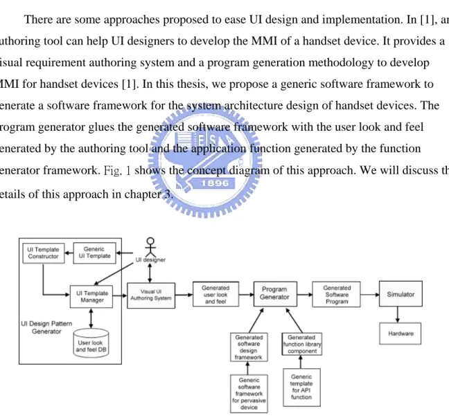
(11) 2.. Implementation. Programmers implement the MMI according to the scenarios, and create a ROMable application.. 3.. Verification. Verify the behaviors of MMI on handset device.. The UI designer usually describes the MMI requirement in the text-based format. Sometimes, both system designer and programmer have difficulty in understanding the requirement specification. The operative MMI cannot be seen until the UI system program has been implemented. In addition, once the UI requirement is changed, programmers have to change their handcrafted application code again.. There are some approaches proposed to ease UI design and implementation. In [1], an authoring tool can help UI designers to develop the MMI of a handset device. It provides a visual requirement authoring system and a program generation methodology to develop MMI for handset devices [1]. In this thesis, we propose a generic software framework to generate a software framework for the system architecture design of handset devices. The program generator glues the generated software framework with the user look and feel generated by the authoring tool and the application function generated by the function generator framework. Fig. 1 shows the concept diagram of this approach. We will discuss the details of this approach in chapter 3.. Fig. 1 Framework of UI Design Pattern Generator and Visual Based Software Construction Model. 2.
(12) 1-3 Overview of this thesis In Chapter 1, we introduce the concept of Man Machine Interface and describe the motivation of this research. Chapter 2 describes the related researches of the concept of software framework, the current software framework of handset devices, and the current method for creating MMI for handset devices. In Chapter 3, we propose a generic software framework that can be used to generate the software architecture of handset devices. In chapter 4, we will discuss how to instantiate a software framework from the generic software framework. Specifically, we create a software framework and construct a simulator. In chapter 5, we discuss the design and implementation of the generic software framework. In chapter 6, we will give several application examples to verify the feasibility and the applicability of the generic software framework. We implemented a software simulator for PC simulation. In chapter 7, we will summarize the study of this thesis.. 3.
(13) Chapter 2 Software Framework for Handset Device and Related Work. In this chapter, we will introduce the related work of software framework, the concept of the software framework, and the current software framework of handset devices. We will elaborate each building block in the framework and address the current method for creating MMI.. 2-1 Framework A framework is a reusable, “semi-complete” application that can be specialized to produce custom applications for specific user domain [4]. It is not a finished work, but rather than a semi-finished software system that intended to be instantiated. A framework defines the architecture for specific application domain and provides the basic building blocks to create them [5].. In [6], it gives a good definition and explanation on framework and is recalled here:. A framework consists of frozen spots and hot spots: Frozen spots define the overall architecture of a software system. For all instantiation of the application framework, the basic building blocks and the relationships between them remain unchanged (frozen). Hot spots are designed to be adapted to the needs of the application under development. When the programmer instantiates a software system from a software framework, he/she must specialize the hot spots of the software framework according to the specific needs and requirements of the system.. One of the primary benefits of software frameworks is "Inversion of control". The framework reacts with external events. When events occur, the dispatcher of the framework. 4.
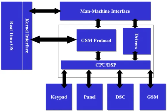
(14) invokes the user-defined function to handle the event. This is also known as the Hollywood Principle: "Don’t call us, we’ll call you." [7].. 2-2 The current software framework for handset devices In the current development method, the building blocks in the design software framework can be schematized as Fig. 2: 1.. Man-Machine Interface (MMI) and relative functions. 2.. Real-time OS (RTOS) and Kernel Interface (KI). 3.. GSM sub-system includes protocol stack and layer 1 driver.. 4.. Hardware devices and device drivers. Fig. 2 The current software framework for handset devices. The responsibility of each building block is described in the following subsections.. 5.
(15) 2-2-1 Man-Machine Interface (MMI). The MMI reacts with external events. It accepts input events and executes corresponding functions. External event include: 1.. User input – key press.. 2.. Connection – originate a call, incoming call.. 3.. Handset status – battery status, antenna status, timer, etc.. The MMI also has the responsibility to represent the MMI scenarios on the display device of handset. The MMI includes a set of scenes. Icons, buttons, and pictures compose each scene. The external events trigger the changeover of scenes according to the current scenario.. 2-2-2 Real-time operation system (RTOS). The RTOS provides resource management services to application system. These services include: 1.. Multithreading management.. 2.. Communication – mailbox, queue.. 3.. Synchronization – event, semaphore, mutex.. 4.. Interrupt service routines.. In a good system design, one usually forbids the application system to accesses the OS resource services directly. Instead, application system accesses the OS resource services via a wrapper – the Kernel Interfaces. The kernel interface is a set of predefined functions, which abstract the implementation details of OS services, and provides a stable interface to application system. Using this approach for system implementation will be easy for porting to another OS platform.. 6.
(16) 2-2-3 GSM subsystem. The GSM sub-system in the framework handles the communication task of the handset. The European Telecommunications Standards Institute (ETSI) defines standards of the GSM cellular phone system [8]. All GSM protocol must conform to the GSM standard to ensure the communication functionalities.. The ETSI also defines standards to extend the ITU-T Recommendation V.250. In the ITU-T Recommendation V.250, it codifies the most common commands used by DTE to control DCE with asynchronous DTE-DCE connections [9]. This is as known as "AT command set", because each command is started with "AT". PC uses the AT command to control its modem. For example, PC dials a phone by sending a string "ATD4125678" to modem.. These standards define a simple interface to control the GSM system. Any software can use the AT command to control the GSM system regardless of the complexity of GSM specification.. 2-2-4 Hardware devices and drivers. Hardware device drivers included in the framework depend on the functional features provided by the handset device. The most common handset devices incorporated in the current cellular phone include:. 1.. Panel (display device).. 2.. Keypad (input device).. 3.. Digital camera (image capturing device).. The panel is the main display device of a handset. Application of the handset calls the panel drivers to draw on the panel. When the design of a handset device phases in a new type of panel, the programmers have to modify the program that relative to panel drivers.. 7.
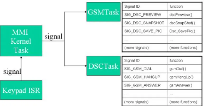
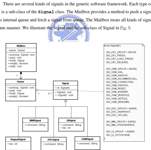
(17) The keypad is a basic input device of a handset. The interrupt service routine (ISR) of the handset is installed to the interrupt vector table of the target system. When the user press the key of handset, the processor of the target device will execute the keypad ISR.. The digital camera provides the function for capturing digital images. The digital camera for handset devices has various kinds of specifications. Programmers have to modify the relative program when the design of digital camera has been changed.. In the current software framework for handset devices, the signaling protocol decouples the relationship between the device drivers and the software applications. We will briefly describe the signaling protocol in next subsection.. 2-2-5 Signal. The signaling protocol decouples the software application and the hardware devices. In the current framework for handset devices, we design several tasks to handle the hardware devices. Each task is a software component that provides an interface to access the hardware services. The interface is signaling protocol. The software applications of a handset device do not access the device drivers directly, but send signals to the relative task to request for hardware services. The task handles these requests by executing the corresponding driver functions.. 8.
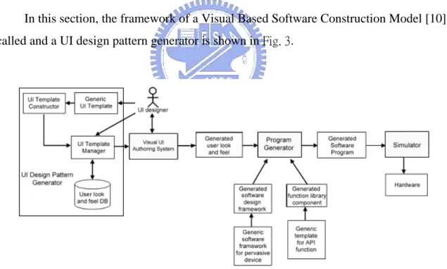
(18) Chapter 3 The Visual-based Software Construction Approach And Generic Software Framework. In chapter 2, we have stated the problems of current development method for creating MMI. In this chapter, we will discuss how the authoring system and the generic software framework help programmers to develop the software application for handset devices.. 3-1 The visual-based authoring system In this section, the framework of a Visual Based Software Construction Model [10] is recalled and a UI design pattern generator is shown in Fig. 3.. Fig. 3 The of UI Design Pattern Generator and Visual Based Software Construction Model. The Visual Based Software Construction approach supports a Visual Requirement Authoring system for UI designers to produce GUI based requirement scenario and specifications. It also supports a Program Generator to generate the target application system as specified in the visual requirement representation. The programmer can produce the target. 9.
(19) application system base on the function binding features provided in the program generator to bind each GUI component with the associated application function [10] [11].. This visual-based construction approach includes the Visual UI Authoring System, which is used to edit the visual representation; the Program Generator, which is used to generate the source code for target platform according to the visual representation generated by the visual UI authoring system; and the Simulator, which is used for software simulation. The main components of this system are described as follows:. Visual UI Authoring System: It is a visual-based editor. The UI designers use the Visual UI Authoring System to create a prototype of user look and feel. Then one can edit this prototype by adding more text or buttons. The UI designers can preview the prototype and modify it. After the authoring is completed, the UI designers have generated the target UI system.. Program Generator: A function binding system generates the program for target system. When the design of user look and feel is satisfied, the UI designers use the program generator to produce the source code of application. The program generator produces the source code according to the visual representation generated by the Visual UI Authoring System. The program generator glues the UI components to the software design framework, and binds function library component with each UI component defined in the generated visual representation.. Software design framework: The program generator applies the software design framework to generate the source code. A software framework is a platform for representing the visual representation that is generated by the authoring system. Programmers can instantiate a software framework from the generic software framework. We will discuss the generic software framework in section 3-2.. Function library component: It is a set of pre-defined library. Programmers implement this function library according to the hardware specification. The program generator applies the function library to produce source code for MMI. The function library component is generated by generic template for API function that will be elaborated in [12].. 10.
(20) Simulator: It is used to simulate the functionalities of the generated target application software on the target cellular phone. Programmers can verify the requirement of the generated software application on PC. If the requirement of the generated software application is fulfill, then one can build the firmware for the target system, download the firmware to the target device, and verify the behavior of the application on target platform.. The UI designer can use the Visual UI Authoring System to edit the user look and feel. He or she can author the user look and feel to produce a visual representation for the target platform. Then the program generator produces the source code for target platform according to the produced visual representation. It generates source code by gluing the software design framework to the library functions. Finally, one uses the simulator to do software simulation.. This visual UI authoring system is especially suitable for the UI designer. The Visualbased authoring system helps the UI designers to create a prototype of MMI in an efficiency way. The designers can edit and preview this prototype and verify its functionality on PC. After the design of MMI is frozen, the UI designer can apply this authoring system to produce the target UI program without writing any textual code. The authoring system uses the code generator to translate the visual representation to source code. The code generator resolves the relationship between the MMI and the functions of device drivers. It applies the designed framework and function library in code generation phase.. 3-2 Methodology for using a software design framework to create software applications for handset devices In this section, the methodology for using a software design framework to create software applications for handset devices is recalled [1] here:. The user look and feel and the application function are glued with the instantiated software framework in the code generation phase. When the design of user look and feel is satisfied, the programmer can use the AP function and UI binder and the Application system program generator to generate the software application program for target platform. The code generation has two phases:. 11.
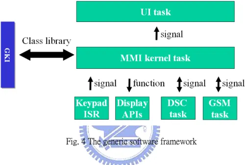
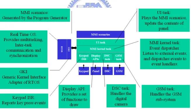
(21) 1.. AP function and UI binder: The AP function and UI binder glues the application function with the instantiated software framework. After the visual representation has met the requirement of user look and feel, the programmers choose function library components to complete the function binding. A function library component is a software component that provides an interface to drive the specific hardware devices. The programmers bind the actor of a scene with the selected function of a function library component.. 2.. Application system program generator: The program generator glues the user look and feel with the instantiated software framework. When the function binding is completed, the program generator translates each scene of the user look and feel to code snips. The program generator collects these code snips and glues them with the program of instantiated software framework.. After the function binding and program generation are completed, the program for target platform is generated. To verify the conformance of the program that was generated from the program generator, the programmers have to compile the program and make an executable image for the target platform.. In this research work, we focus in the program generator. Specifically, a generic software framework for handset devices is proposed to generate the target software design framework. In the following section, we present the architecture of the generic software framework.. 3-3 Architecture of the generic software framework The generic software framework for handset devices is a multitasking, event-driven system. There are eight parts in the generic software framework, as shown in Fig. 4: the signaling protocol is the inter-task communication interface for software component; the UI task represents the MMI scenarios; the MMI kernel task listens to events and dispatches events to corresponding tasks; the GSM task handles the GSM-related events and provides communication services; the DSC task handles the digital camera; the keypad ISR report 12.
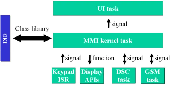
(22) keypad event to the MMI kernel task; the Display API defines a set of functions which the UI task use to draw on panel; the GKI class library provides the functionalities to create these tasks and defines the interface of signaling protocol.. The MMI kernel task acts as the ‘headwaiter’ in the generic software framework. The other tasks act as ‘waiters’: they accept request signals sent from MMI kernel task and perform services by executing application functions.. Fig. 4 The generic software framework. Signaling protocol is an inter-task communication and synchronization mechanism in the generic software framework. There are four tasks in the generic software framework: UI task, MMI kernel task, GSM task and DSC task. Each task is a software component that provides pre-defined services. A task accesses the other task’s services via an interface, the signaling protocol. The MMI kernel task requests hardware services by sending signals to other tasks. Note that the MMI kernel task does not call the driver functions directly. This means the generic software framework provides a hardware-independent platform for software applications. The signaling protocol decouples the interfaces and implementations of the hardware devices, as shown in Fig. 5:. 13.
(23) Fig. 5 Signaling protocol decouples the software components of the generic software framework. Each task has a mailbox for storing signals. The interfaces of sending and receiving signals to each other are the same. The behavior to process signal depends on each task.. The UI task represents the MMI scenarios that generated by the program generator. It displays the contents of the current scene on panel. The MMI kernel task request the UI task to change the scene by sending signals. The UI task processes these signal by redrawing the content of the current scene on the panel.. The MMI kernel task acts as an “event listener” and “event dispatcher” in the generic software framework. It listens to external events and dispatches events to corresponding event handlers, such as UI task, GSM task and DSC task. The MMI kernel task dispatches jobs to these tasks by sending signals to them.. The GSM task is a software component that handles the GSM sub-system and provides a stable interface via the signaling protocol. The MMI kernel task requests for the GSM services by sending signals to GSM task. The GSM task reports the communication status by sending signals to MMI kernel task. The interface of the GSM task and GSM-subsystem is the AT command interface, which is defined in [8] and [9]. The GSM task must conform to the signaling protocol to provide the services of GSM sub-system.. The DSC task is a software component that handles the digital camera hardware. It controls the DSC module to perform the services of preview, snapshot, and so on. The DSC 14.
(24) task must conform to the signaling protocol of the generic software framework. The details of DSC can be found in [12].. The Keypad ISR handles the key press events and reports it to MMI kernel task. The keypad is a basic input device of a handset. The keypad ISR is registered to the interrupt target system. When a user presses the key, a hardware interrupt triggers the CPU to execute the keypad ISR to send a signal to MMI kernel task.. The Display API is a set of service routine that implements the drawing functions on the panel of handset device. The UI task uses these functions to draws pictures, buttons and icons on panel. The implementation of Display API depends on the hardware device. A complete study of Display API is beyond the scope of this thesis.. The Generic Kernel Interface (GKI) is a class library that wraps the OS. It encapsulates the implementation of OS, such as multitasking, inter-task communication and synchronization, and provides a stable interface for software application. When the programmers port the application to another OS, they do not need to modify the software application, but only need to rewrite the GKI library. Each task in the generic software framework is a sub-class of GKI Task class. The GKI class library implements the functionality of signaling protocol.. In the next section, we present a comparison study between the software framework and generic software framework.. 3-4 A comparison between software framework and generic software framework. A software design framework is a reusable architecture for creating software applications for handset devices. A generic software framework is a template of software design framework. A software design framework is specialized to target OS and hardware device, where the generic software framework defines these interfaces and left the implementation issues for software framework.. 15.
(25) The generic software framework provides a template for implementing the software design framework for specific OS and hardware device. It defines the algorithm to access the services of OS and hardware device drivers. The software design frameworks overwrite to provide concrete behaviors. Table. 1 gives a comparison between software framework and generic software framework from different aspects:. Table. 1 A comparison between software framework and generic software framework.. Generic Software Framework. Software Framework. Software architecture. Concept. A reusable software architecture for handset devices.. Flexibility. Provides an OS-dependent and hardware-dependent platform for handset devices. Components Tasks, signaling protocol, GKI class library. Implementation Porting the GKI class library to issues target OS. Implement the tasks, keypad ISR and Display API for target device. GKI Specialized to the target OS platform. Keypad ISR Implemented for the keypad device of target system. Display API Implemented with the functions of the target panel device. DSC task Performs DSC services by executing the functions of DSC device drivers. GSM task Performs communication services by handling AT commands.. 16. A generic template of reusable software architecture for handset devices. Defines the generic methods to access the services provided by OS and hardware devices. Same. Provides the porting guidelines of GKI and tasks.. Provides generic methods to access the services of OS. Defines the behaviors of keypad ISR for the MMI kernel task. Defines the drawing functions for UI task. Defines the generic behavior of DSC devices. Defines the generic behaviors of GSM sub-system..
(26) The visual-based UI authoring system helps to create the application based on the prerequisites of software design framework. The authoring system does not need to know the implementation details of OS and hardware device. The details are encapsulated behind the software design framework. A more details treatment on the generic software framework for handset devices will be given in chapter 4 and chapter 5.. 17.
(27) Chapter 4 Software Framework Generation Based on Generic Software Framework. In chapter 3, we outline the structure of a generic software framework and present the major components description in generic software framework. In this chapter, we will discuss how to instantiate a software framework from the generic software framework.. 4-1 Software framework generation based on the generic software framework To create a software framework for handset device, the generic software framework must be specialized for target OS and hardware devices. The unresolved components headed to be instantiated in the proposed generic software framework include:. 1. Generic Kernel Interface (GKI). 2. GSM task. 3. DSC task. 4. Keypad ISR. 5. Display API.. The details of DSC task can be found in [12], thus it is not elaborated here.. In addition, a complete treatment for the Display API is beyond the scope of this thesis. In the simulator, we use the Borland Visual Component Library (VCL) to implement the Display API for simulation purpose.. The program generator takes the generated software design framework to produce the target platform for the application program. A software design framework is a “user-defined 18.
(28) specialization” instance of generic software framework. A software framework is specialized for a specific OS and hardware device after the following actions are taken:. 1.. Porting the GKI library to the target operating system. In the proposed generic software framework, in this case, the programmer need to overwrite the Task class to carry out this duty. We will give a porting example of Win32 platform in the chapter 5.. 2.. Porting the Keypad ISR for the keypad device of target handset. The Keypad ISR handles the key input events and report events by sending signals to MMI kernel task.. 3.. Porting the Display API for the panel device of target handset. The Display API allows application to draw image and text on panel.. 4.. Implement the GSM task according to the signaling protocol. The communication request and report of the status to MMI kernel task will be defined here.. 5.. Implement the DSC task according to the signaling protocol. The DSC task that handles the DSC module will be defined here. The details can be found in [12]. In following sections, we will discuss how to instantiate the generic software framework to create a target software framework.. 4-2 Generic Kernel Interface (GKI) In this section, we will explain how to port the GKI class library to a target OS. At first, we briefly introduce how to create a thread. The Task composites a Mailbox to store signals. We will discuss the implementation principle of mailbox. After the Task create a thread, it is able to send signals and receive signals. The sendSignal and recvSignal are introduced at last. Here we give examples that porting the GKI to the Win32 OS platform. We implement all samples in this section in C++ language.. 19.
(29) The Generic Kernel Interface is designed to adapt the application to different OS platform. There are three major steps in this porting process: 1.. Implement the Task class for multi-tasking.. 2.. Implement the Mailbox for sending and receiving signals.. 3.. Overwrite the sendSignal and recvSignal methods of Task class.. 4-2-1 Task. To create a thread on Win32 platform, one has to prepare the entry function start_address for thread execution and the parameter arglist for entry function. Then call the _beginthreadex to create a thread [13]. According to C++ specification, when we assign a method of Task to start_address, the method must be static, as shown in the following Program sample 1.. unsigned long _beginthreadex( void *security, unsigned stack_size, unsigned ( __stdcall *start_address )( void * ), void *arglist, unsigned initflag, unsigned *thrdaddr ); Program sample 1 We call the _beginthreadex in the Task::start method [14] [15]. Here we pass “this” to the _beginthreadex as the parameter of entry function, as shown in Program sample 2:. bool Task::start() { hThread = _beginthreadex(NULL, 0, entryFunc, (LPVOID)this, 0, &dwThreadID); } Program sample 2. 20.
(30) When the start method of the Task class is invoked, it will call the OS service routine to create a thread for the current application program. The thread will take the pointer of the Task object as parameter (this) and execute the entry function entryFunc.. Porting the Task class to another OS is in the same manner. Call the OS API to create a thread in the Task::start method, and keep the thread handle for later manipulation.. 4-2-2 Mailbox. The mailbox is a common concept among RTOS. Most RTOS has ready-made solution of mailbox. If there is not a suitable solution for mailbox, it is still easy to implement a Mailbox class. Here is the guideline to implement a mailbox:. 1.. A mailbox provides methods for operating signals: bool empty(void); Signal * front(void); void push(Signal *); void pop(void);. 2.. A mailbox composites a queue to hold signals: queue<Signal *> signalQueue;. 3.. The mailbox provides a wait method to prevent from pooling signal queue. When the wait method is called, the calling task will be blocked until a signal is available: void wait(void);. 4. An atomic-lock guards the signal queue to prevent from synchronous access.. 21.
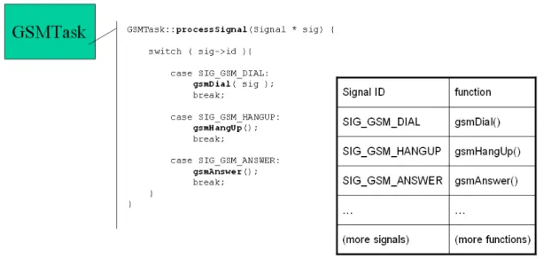
(31) 4-3 GSM task The GSM task is a software component that provides the GSM communication services in the generic software framework. It encapsulates the GSM sub-system and provides GSM service via the signaling protocol. All signals send to GSM task will be processed in the processSignal method. To implement a GSM task to handle the target GSM module, one has to overwrite the processSignal method of the GSM task. We will illustrate the concept of overwriting the processSignal method of GSM task in Fig. 6.. Fig. 6 The signal-function table of GSM task. To overwrite the GSMTask::processSignal, we have to pair the corresponding device functions for each kind of incoming signal. There exists a relationship between the type of signal and the corresponding function. Each kind of signal stands for a corresponding GSM service. We show the signal-function as a table in the right hand side of Fig. 6. Programmers can provide more services to GSM task by adding more signals and functions in the GSMTask::processSignal method. The parameters for calling the functions are attached in the context of signal. The GSM task retrieves the parameters from the signal and pass these parameters to the AT command interface.. 22.
(32) 4-4 Keypad ISR The Keypad ISR is executed on the key press interrupt. Each time the key is pressed, the processor executes the Keypad ISR to send a signal to MMI kernel task. To create a keypad ISR for target software framework, one must implement the keypad ISR and register the keypad ISR on the interrupt vector table of the target system.. 4-5 The created software framework When the GKI class library is ported to the target OS, and the GSM task, DSC task, and keypad ISR are all implemented for a specific hardware device, the hot spots of the generic software framework are resolved, thus, a software framework is created. Fig. 7 schematizes the overview of the software architecture of the created software framework:. Fig. 7 The software architecture of the created software framework. The created software framework provides a platform for representing the MMI scenarios generated by the visual-based UI authoring system. The GKI class library wraps the operating system and provides the functionalities for creating tasks and signaling protocol. The UI task can represent the MMI scenarios generated by the visual-based UI authoring 23.
(33) system. The MMI kernel task interacts with input events and dispatches signals to other tasks. The Keypad ISR is invoked to report the key press events when user presses the keypad. The UI task uses the Display API to draw images on panel. The DSC task handles the DSC module. The GSM task controls the GSM sub-system.. 24.
(34) Chapter 5 System Design and Implementation. In chapter 4, we have discussed the software architecture of generic software framework. In this chapter, we describe the design and implementation details of the generic software framework. The design and implementation of GKI class library, the UI task, MMI kernel task, GSM task, DSC task, and Keypad ISR are discussed in the following sections.. The software architecture of the generic software framework is recalled and is shown in Fig. 8.. Fig. 8 The generic software framework. 5-1 Design and Implementation of Generic Kernel Interface (GKI) GKI is a class library that provides functionalities of multitasking, inter-task communication, and synchronization that are implemented by the synchronized objects. The synchronized objects - such as mutex, critical section, lock, and semaphore - are platform-. 25.
(35) dependent. In this study, we use C++ to implement the multitasking, threads, and thread safety [16].. We implement these synchronized objects as the wrapped objects for the platform independent consideration. In this study, when we need to port the program to another platform, we will not need to restructure our codes, but only need to rewrite these synchronized classes.. We implement several synchronized objects to construct the GKI class library:. 1.. Signal - Tasks communicate to each other via signals.. 2.. Task - GKI provides the Task class to create tasks. The implementation details for creating tasks on different OS are encapsulated in the Task class.. 3.. Mailbox - Stores signals. Each task has its own mailbox.. Each Task in the GKI has a mailbox to store signals. Both the sendSignal and recvSignal of the Task class are relevant to mailbox. The following Program sample 3 shows the relationship between Task, Mailbox and Signal:. Task::sendSignal(Signal * sig) { mailbox.push(sig); }. Signal * Task::recvSignal() { mailbox.wait();// wait until a message is received. Signal * sig = mailbox.front(); mailbox.pop(); return sig; } Program sample 3. 26.
(36) 5-1-1 Signal. In the generic software framework, signals are used for tasks to communicate and synchronize to each other. The MMI kernel task coordinates event invocations and event executions by using signals. When an external event is triggered, a signal is constructed and sends to MMI kernel task. The MMI kernel task will process these signals and dispatch them to other task.. Signals are stored in the mailbox of a task. Each task has a public method sendSignal for other task to send a signal to itself. The private method recvSignal fetches a signal from mailbox.. There are several kinds of signals in the generic software framework. Each type of signal is a sub-class of the Signal class. The Mailbox provides a method to push a signal into its internal queue and fetch a signal from queue. The Mailbox treats all kinds of signals in the same manner. We illustrate the Signal and the sub-class of Signal in Fig. 9.. Fig. 9 Class diagram of Signal. 27.
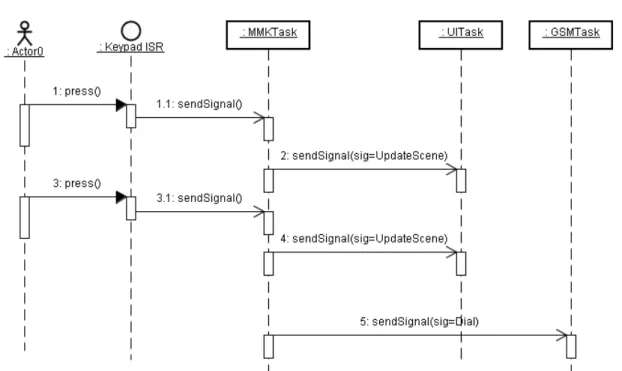
(37) In order to represent each kind of external events, we define several types of signal, such as KeypadSignal, MMISignal, DSCSignal, UISignal and GSMSignal. These signals derive from the Signal class and overwrite the virtual destructor that is defined in base class. The Signal class defines the pure virtual destructor which derive classes provide a concrete implementation. When program deletes a signal, the destructor of the signal is invoked to release the resources contained in the signal.. A sub-class of Signal has a SignalId data field for identification and several data fields for storing messages. When a task receive a signal, it identifies the signal identification to decide what action to take, and obtains the parameters of functions from the messages.. Here we give two examples to explain the usage of signals. The first example, as shown in Fig. 10, illustrates how signals are used to make a phone call. When user dials several numbers, the Keypad ISR sends a series of key-press signals to MMI kernel task. The MMI kernel task will send signals to trigger the UI task to update the current scene and redraw the scene on panel. After user press the OK key, the MMI kernel task will receive the signal, and send another signal to GSM task to make a phone call.. Fig. 10 A sequence diagram of making a phone call 28.
(38) Another example is given in Fig. 11 to show the sequence diagram of incoming call. When the GSM task is notified by incoming call, it sends an INCOMMING_CALL signal to MMI kernel task. MMI kernel task will send another signal to inform UI task to update the MMI scenario. After the user press the OK key to accept the call, a hardware interrupt is happened, and the corresponding interrupt service routine (ISR) is triggered to send a KEY_PRESS signal to MMI kernel task. Again, the MMI kernel task sends another signal to inform UI task to update the MMI scenario.. Fig. 11 A sequence diagram of incoming call. 29.
(39) 5-1-2 Task. The Task class gives a skeleton for common behavior on multitasking, inter-task communication and synchronization. There are four tasks in the generic software framework, UI task, MMI kernel task, GSM task and DSC task. Each task is a sub-class of Task class. We use the Template Method pattern [17] to design the Task class and these sub-classes. Fig. 12 shows the design pattern of tasks using the Template Method pattern.. Fig. 12 A class diagram of tasks based on the Template Method pattern. The Task provides a template for those tasks defined in the generic software framework. It defines concrete methods that subclass can choose to reuse or overwrite; it defines primitive methods that the subclasses of Task must implement. The implementation policy of these primitive methods varies with OS and hardware device.. The Task class provides these methods: 1. bool start(); 2. virtual void run(); 3. public void sendSignal(Signal * msg); 4. protected Signal * recvSignal(void); 5. protected virtual void processSignal(Signal * msg) = 0; 6. protected virtual void destroySignal(Signal * msg) = 0; 30.
(40) The start is a concrete method that creates a thread for the current application.. The run is a template method that receives signals and process signals. Successors of Task may choose to overwrite this method and insert the code that should be executed, or reuse the default implementation.. The sendSignal is a concrete method that pushes a signal to its internal mailbox.. The recvSignal is a concrete method that fetches one signal from the mailbox. The recvSignal is a private method. This is because each task has its own duty to process signals, and this internal information need to be encapsulated into a task.. The processSignal is a primitive method that processes the signal that was sent to the task. The subclasses of Task must override this abstract virtual function based on the behavior of processing signal.. The destroySignal is a primitive method that releases the memory that is allocated for the signal. The subclass of Task must override this abstract virtual function to release the resources allocated for signals.. The concrete methods, sendSignal and recvSignal, provide the common interfaces to send and receive signals.. The abstract methods, processSignal and destroySignal, are left for derived classes to provide concrete implementations. The behavior to process signals depends on the requirement of each derived class.. 31.
(41) When the start method is invoked, a thread is created. Here we give a program example to illustrate the algorithm of start method:. bool Task::start() { hThread = _beginthreadex( NULL, 0, entryFunc, this, 0, &dwThreadID); } Program sample 4. The created thread will take the pointer of Task object as parameter and call the entryFunc. The entry function Task::entryFunc is a static method that accepts an argument - this, which is the only point to distinguish one task from the others. After the thread is created, the OS will execute the static entryFunc method in the context of thread.. In the Task::entryFunc, the program references the pointer of the Task object. After initialization, the program enters run method. When the task has completed its job, the program calls the exit to cleanup. The following program example illustrates the algorithm of entryFunc method:. unsigned __stdcall Task::entryFunc(LPVOID lpParameter) { Task * pTask = reinterpret_cast<Task*>(lpParameter);. pTask->initialize(); pTask->run(); return pTask->exit(); }. 32.
(42) Program sample 5. The run method contains the user-defined program for the Task. The implementation of run method provides a default design for subclass of Task. In run method, tasks receive signals from its mailbox, and process signals in their primitive processSignal, here is a program example:. void Task::run() { Signal * sig; while ( ! terminate ){ sig = recvSignal(); processSignal(msg); } } Program sample 6. Programmers can choose to reuse this implementation or have another implementation for the subclass of Task. In UI task, GSM task, and DSC task, we choose to reuse the default implementation of run method defined in Task class. In the MMI kernel task, we choose to overwrite this default implementation. Following program example explains the overwritten run method of MMI kernel task:. void MMITask::run() { Signal * sig; while ( ! terminate ){ sig = recvSignal(); updateCurrentState(sig); dispatchSignal(sig); } } Program sample 7. 33.
(43) 5-1-3 Mailbox. Every task in the generic software framework has a Mailbox to store signals. The mailbox provides interfaces to push and retrieve signals. We use the “Strategy” pattern [17] to design and implement the Mailbox class. Fig. 13 shows the strategy pattern consists of a Mailbox class and a set of Oueue strategy classes:. Fig. 13 Mailbox design pattern based on the Strategy pattern. The Mailbox (Context) composites a reference to a Queue object. The Queue is an abstract class (Strategy) which defines the common interface to all strategies. The Win32Queue and NucleusQueue are subclasses of Queue (Concrete Strategy) that are implemented for different OS. Sub-classes of Queue have similar behaviors and provide various implementations strategies for Mailbox. This design makes it easy to port the GKI Mailbox on different OS.. 34.
(44) The Mailbox class composites a queue and delegate the duty of storing signals to its queue. It provides methods to push, to fetch and to pop signals. The Mailbox provides a "wait" method to prevent from pooling its queue, which can greatly save lots of computing time. The Mailbox maintains atomic-access mechanism to access its queue.. Here we give examples to explain how the Mailbox is used to store and retrieve signals. Fig. 14 illustrates the sequence of sending a signal to a task. The receiver task pushes the signal into its mailbox. The mailbox of the receiver task delegates this duty to the internal queue object.. Fig. 14 Sequence diagram: task1 send a signal to task2. Fig. 15 depicts the sequence of fetching a signal from a mailbox. The task2 is waiting for a signal after it calls the wait method. When a signal is available, the task2 fetch the signal by calling the front method and disposes this signal by calling pop method.. Fig. 15 Sequence diagram: Task2 fetch a signal from its mailbox 35.
(45) 5-2 UI task The UI task maintains a set of scenes that was generated from the visual-based UI authoring system. Each scene is composed with icons, buttons and pictures. The MMI kernel task sends signals to UI task to trigger the changeover of scenes.. The UI task applies the State pattern to maintain the transition of scenes, as shown in Fig. 16.. Fig. 16 Collaboration diagram: UI task. 36.
(46) The program generator translates the visual UI requirement into code snips for UI task. We will illustrate the implementation of UI task by the following pseudo code:. UITask::UITask() { // the program generator inserts the UI scenes: entry.first = "Scene223"; entry.second = Scene223::Instance; mSceneMap.insert( entry ); // ...(more UI scenes) // The program generator inserts the control scenes: entry.first = "IncommingCallScene"; entry.second = IncommingCallScene::Instance; mSceneMap.insert( entry ); // ...(more control scenes) } Program sample 8. The program generator inserts the MMI scenes and the control scenes into the program of the UI task. The UI task will execute these code snips at run time. When the UI task receives a signal with the identification set to SIG_UI_GOTOSCENE, it handles this signal by 1: look up for next scene; 2: update the current scene; and 3: redraw the panel for the current scene. Here we give the pseudo code to explain how the UI task handles the SIG_UI_GOTOSCENE signal:. void UITask::processSignal(Signal * sig) { switch(sig->id) { case SIG_UI_GOTOSCENE: // find the next scene in the lookup table // update the current scene // redraw the current scene break; } } Program sample 9. 37.
(47) 5-3 MMI kernel task The MMI kernel task is an “event listener” and “event dispatcher” in the generic software framework. It handles events by dispatching these events to other task. This is especially important for a user responsive system. When an event requires a long time to be handled, the MMI system can still keep the event highly responsive. User may want to know the progress of event or cancel the event that was launched before. With the responsive listener, the system can react to external events quickly. The design of MMI kernel task is based on the "Active Object" pattern [18], which is shown in Fig. 17:. Fig. 17 Collaboration diagram: MMI kernel task. The MMI kernel task listens for external events and reacts to them. It maintains its states and reacts to events according to the current status. When a signal (as event) is fetched from the signal queue, the MMI kernel task processes this signal in the following order:. 38.
(48) 1. Recognize the type of the signal. 2. Update the current state with this signal. 3. Look up for the event handler. 4. Dispatch this signal to the dedicated task to handle this signal. Fig. 18 is the state diagram that represents the internal states of MMI kernel task for handling the events in GSM sub-system:. Fig. 18 Internal states of MMI kernel task. 39.
(49) 5-4 GSM task The GSM sub-system handles all communication events and provides the mobile communication services such as to dial a phone, to hang up a call, to indicate an incoming call, and to accept a call, and so on.. We model the GSM sub-system as a modem, and design the GSM task to handle the GSM sub-system. With the AT command interface [8], the GSM task can control the GSM sub-system and simulates the GSM communication features.. The GSM task waits for incoming signals from MMI, decides the action to be taken, and sends the AT command to GSM module. The GSM task provides three kinds of GSM communication services: 1. Originate a call 2. Answer a call 3. Hang up a call. Each service is invoked by a corresponding signal, as below: 1. SIG_GSM_DAIL 2. SIG_GSM_ANSWER 3. SIG_GSM_HANGUP. In addition, the corresponding functions to perform these services are listed below respectively: 1. dial() 2. answer() 3. hangUp(). The GSM task inherits from the Task class and overwrites the processSignal method. In processSignal, we pair the corresponding device functions with signals. Here we use a switch-case statement to discriminate the action needed to handle these signals. In addition, the pseudo-code of the GSM task is list as below:. 40.
(50) void GSMTask::processSignal(Signal * msg) { switch (sig->id) { case SIG_GSM_DAIL : dial(); break; case SIG_GSM_ANSWER : answer(); break; case SIG_GSM_HANGUP : hangUp(); break; } } Program sample 10. Here we give an example to explain how the MMI kernel task requests the GSM task to make a phone call. When the MMI kernel task decides to make a phone call, it sends a signal to GSM task to perform this service. The sending signal contains the phone number to dial and the signal identification is set to SIG_GSM_DIAL. When the GSM task receives this signal, it executes this request by sending an AT command to the GSM module. Fig. 19 illustrates the concept of this dialing process:. Fig. 19 Collaboration diagram: Making a phone call. 41.
(51) 5-5 DSC task The DSC task provides functions of digital camera. When the user requests the DSC module to take a snapshot The MMI kernel task processes the request by sending a signal to DSC task. The DSC task processes the request by calling corresponding drivers to perform the service. The detail design of DSC task and the device drivers can be found in [12].. Here we give an example to elaborate how the MMI kernel task and the DSC task cooperate to perform a snapshot. When the MMI kernel task decides to make a snapshot, it creates a signal, set the identification field to SIG_DSC_SNAPSHOT, and send to DSC task. When DSC task receives this signal, it executes the corresponding driver function to drive the DSC module to make a snapshot. Fig. 20 shows the collaboration diagram of taking a snap shot.. Fig. 20 Collaboration diagram: Take a snap shot. Here we explain the implementation of the DSC task by giving the following pseudo code:. void DSCTask::processSignal(Signal * msg) { switch ( msg->sid ){ case SIG_DSC_SNAPSHOT: // perform snapshot break; } } Program sample 11 42.
(52) 5-6 Keypad ISR The keypad ISR sends signal to MMI kernel task on key press events.. The processor of the handset device executes the Keypad ISR on the key press interrupt. Each time the key is pressed, the processor is triggered by a hardware interrupt. Then the processor executes the Keypad ISR to send a signal to MMI kernel task.. The MMI kernel task need to distinguish two kinds of keypad events: "press" or "long press". Consider the ‘cancel’ key of a handset. In most case, this key is designed to have two meanings: one is for canceling the current operation, and the other is for powering off the handset. Therefore, the Keypad ISR has to distinguish the difference between the normal “press” and the “long press”, and send different signal to MMI kernel task. Both types of signals have different meanings, and the way to handle these two signals depending on the design of MMI scenarios. The Keypad ISR will keep the states and report the key pressed events according to the current state. The states diagram of the keypad ISR is described in Fig. 21:. Fig. 21 States diagram of keypad ISR. 43.
(53) The following pseudo code explains the algorithm of the keypad ISR:. void KeypadISR(void) { // scan the keypad to get the pressed code int key = hw_scankey(); if ( !bLongPress && (0 == iKeyPress) ) { // perform key press event KeypadSignal *sig = new KeypadSignal; sig->sid = SIG_KEY_PRESS; sig->mKey = key; MMITask->sendSignal(sig); } iKeyPress++; if ( LONG_PRESS_THRESHOLD == iKeyPress ) { // perform long press event bLongPress = true; iKeyPress = 0; KeypadSignal *sig = new KeypadSignal; sig->sid = SIG_KEY_LONG_PRESS; sig->mKey = key; MMITask->sendSignal(sig); } } Program sample 12. 5-7 Display API The Display API is a set of functions that draw images on panel. A complete study of the Display API is beyond the scope of this thesis. In this study, we use the Borland VCL [19] to emulate the Display API. A detailed treatment on this subject can be found in [20].. 44.
(54) Chapter 6 Simulation and Application Examples. In this chapter, we explain the run time behavior of the generic software framework. In order to verify the generic software framework and the user look and feel that generated from the authoring system, we implemented a software simulator that can be executed in PC environment.. 6-1 Introduction of the simulator The simulator helps us to verify the design of the MMI scenarios. It can accept key press, display the operation status, and execute the corresponding functions. We show the look and feel of the simulator in Fig. 22:. Fig. 22 The look and feel of the simulator. We can originate a call or accept a call on the simulator. When we press the buttons on the simulator, the UI task will display a series of numbers on the panel of the simulator.. 45.
(55) 6-2 The design and implementation of the simulator In this section, we will make a tutorial on the design and implementation of the simulator. The simulator has several components that will be elaborated in 6-2-1. We collect these software components and compile to an executable program. The simulator is executed on PC and it controls the external devices, the DSC module and the GSM module, via the data cable.. 6-2-1 The software architecture of the simulator The software architecture of the simulator includes GKI class library that was specified to Win32 OS platform; a software design framework that was specified to simulation environment; a set of MMI scenarios that was generated by the visual-based UI authoring system; and a graphic user interface (GUI) to stand for the keypad and the panel. The software architecture of the simulator is shown as Fig. 23.. Fig. 23 The software architecture of the simulator. The simulator combines a graphic user interface (GUI) with a software design framework. On the left hand side of Fig. 23 is the GUI of the simulator. The GUI has a panel on the top and a keypad on the button. The simulator displays UI to the panel and handles user input from the keypad. When user presses the keypad, the Keypad ISR reports the keypressed events to MMI kernel task, and the UI task represent the MMI scenarios on the panel. Here we use a real handset to stand for the GSM sub-system and a DSC evaluation board to stand for a DSC hardware device.. 46.
(56) 6-2-2 The design and implementation of the simulator We create a software design framework from the generic software framework to fulfill the requirement of simulation. The generic software framework is specialized to Win32 OS platform and hardware devices. Fig. 24 illustrates the creation of the software design framework.. Fig. 24 Create a software design framework for simulator. The GKI of the software design framework is specific to Win32 platform. We implement the GKI class library for Win32 OS platform. The methods for porting GKI class library are mentioned at 5-1 Design and Implementation of Generic Kernel Interface (GKI).. The keypad ISR of the simulator is implemented as an event handler of the GUI. When user presses the keypad, the event handler is invoked to report this event to MMI kernel task.. In this thesis, we do not implement the Display API but use the Borland Visual Component Library (VCL) to perform this service instead. By the help of VCL, each actor in the MMI scenarios has a method to draw itself on the panel.. The GSM task interacts with the GSM sub-system via AT command interface. A serial port is opened to transact the AT commands and response between software design framework and GSM sub-system.. The DSC task and the DSC evaluation board are connected by a USB cable. The DSC task sends commands to DSC module via the USB data cable. The DSC module processes commands and response the execution result to DSC task.. 47.
(57) 6-3 Application examples The program generator glues the MMI scenarios with the software design framework. Fig. 25 depicts the process flow of program generation:. Fig. 25 The program generator combines the user look and feel with the design software framework Here we explain how the user look and feel is combined with the application function.. The UI designer uses the visual-based authoring system to edit the UI requirement and produces user look and feel. The UI designer uses the function binder to combine the application functions with the user look and feel. Then the program generator translates the relationship between application functions and user look and feel into code snips, and adds these code snips to the program of UI task. After the program generation is completed, the programmer compiles the program to a software application for handset devices.. When the handset application is running, the MMI kernel task accepts external events and dispatches event to corresponding task. When the MMI kernel task receives a signal, it will look up for the next scene in the MMI scenarios, update the current scene and send signals to UI task to update the current scene. Then the UI task will redraw the panel to represent the current scene. The MMI kernel will also send signals to request the DSC task 48.
數據
+7
相關文件
Complex Instruction Set Computers (CISC). complicated
volume suppressed mass: (TeV) 2 /M P ∼ 10 −4 eV → mm range can be experimentally tested for any number of extra dimensions - Light U(1) gauge bosons: no derivative couplings. =>
• Formation of massive primordial stars as origin of objects in the early universe. • Supernova explosions might be visible to the most
Overview of a variety of business software, graphics and multimedia software, and home/personal/educational software Web applications and application software for
2.注重實地演練,角色扮演、跟隨經驗、實地參訪及邀請業界主管演講方 式,使學生能從「經驗中學習」
Experiment a little with the Hello program. It will say that it has no clue what you mean by ouch. The exact wording of the error message is dependent on the compiler, but it might
SaaS 軟體即服務 ( Software as a Service) 建立在 PaaS 、 IaaS
In the development of data acquisition interface, matlab, a scientific computing software, was applied to acquire ECG data with real-time signal processing.. The developed
