行政院國家科學委員會專題研究計畫 成果報告
抗諧振反射光波導(ARROW)結構之二維光子晶體波導研究
計畫類別: 個別型計畫
計畫編號: NSC92-2215-E-009-047-
執行期間: 92 年 08 月 01 日至 93 年 07 月 31 日
執行單位: 國立交通大學電子工程學系暨電子研究所
計畫主持人: 黃遠東
報告類型: 精簡報告
處理方式: 本計畫涉及專利或其他智慧財產權,1 年後可公開查詢
中 華 民 國 93 年 12 月 27 日
ARROW-based photonic crystal waveguides
Yu-Lin Yang, Shih-Hsin Hsu, Ming-Feng Lu, and Yang-Tung Huang
Department of Electronics Engineering and Institute of Electronics
National Chiao Tung University
1001 Ta-Hsueh Road, Hsinchu, Taiwan,Republic of China
TEL: 03-5712121 ext. 54212, FAX: 03-5724361, E-Mail:[email protected]
(NSC92-2215-E-009-047)
Abstract| A new photonic crystal waveguide based on ARROW structure is proposed to solve the coupling issue with a ¯ber in the vertical direction. The design and performance of this device are discussed.
Keywords: Integrated optics, antiresonant re°ecting optical waveguide, photonic crystal waveguide.
1. Introduction
Photonic crystals are arti¯cial optical materials with periodic changes in dielectric constant, analogous to the crystal structure of semiconductors, and photonic band gaps (PBG) can be created for certain range of photonic energies [1]. The propagation of light for that range is forbidden. By incorporating line defects into PC with PBG, they can work as strongly con¯ned waveguides. In general, the optical con¯nement in these structures is supported by PBG guiding in a lateral plane and that use index guiding in vertical direction, which are called as PC slab waveguides.
In order to sustain PBG, the core size of traditional PC slab waveguide is less than one micron but optical ¯bers have sizes on the order of a few micron. Coupling becomes a critical problem between PC waveguides and ¯bers due to the mismatch of core sizes. The coupling issue also limits the measurements and further applications of PC devices. There are many couplers proposed for e± cient coupling, including gratings, mirrors, and tapered structures. However, those can solve the lateral coupling issue only.
ARROW structures utilize the Fabry-Perot cavities as the re°ectors instead of the total internal re°ection [2]. In comparison with conventional waveguides, ARROW has some great features: relatively large core size suitable for e± cient connection to single-mode ¯bers and °exible structure design roles. It is a new application to design PC waveguides with ARROW structure in the vertical direction for e± ciently coupling with general single-mode ¯bers.
In this presentation, the design of ARROW-based PC waveguides will be discussed. Photonic band structures and transmission e± ciencies of ARROW-based PC waveguides calculated by commercial software package R-Soft V.5.1 will be presented.
2. Design of ARROW-based PC waveguides
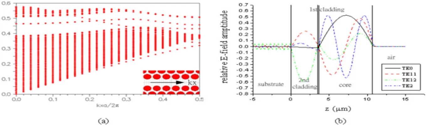
The design of ARROW-based PC waveguides is divided into two parts, the lateral plane and the vertical direction. In the lateral plane, the periodicity of our device is triangular lattice arranged by air holes, and a 2D PC waveguide is created by removing a row of PC. The TE band map is calculated with the plane wave expansion method (PWE) and supercell approximation [3], and the result is shown in Fig. 1(a). The simulation parameters are: the refractive index ncof background material is 1.8 (SiOxNy); ra=a = 0.4 due to maximum band gap at the ratio, where raand a is the radius of air hole and lattice constant,
respectively. The complete band gap exists within the normalized frequency from 0.441 to 0.504 (a=¸). In the range of band gap, there are two defect modes induced. The upper is even, and the lower is odd, respectively.
ARROW structures consist of two claddings between core layer and substrate. The ¯rst cladding is with a low index and the second is with a high index. To analyze ARROW structures in the vertical direction, the transfer matrix method [4] is used. The refractive index of the core and of the second cladding layer is nc= nl= 1.8 (SiOxNy), and of the ¯rst cladding layer is nh= 3.5 (poly-Si), respectively.
The free-space operating wavelength ¸0is 1.55 ¹m. To attain a low insertion loss for an ARROW-based
PC Waveguide, the thickness dcof core layer is chosen as 7.00 ¹m. The thicknesses of the ¯rst cladding
and of the second cladding layers are dh = 0.12 and dl = 3.50 ¹m, respectively, by satisfying the
transverse antiresonance condition [2]
di= ¸0 4ni " 1¡ µn c ni ¶2 + µ ¸ 0 2 nidc ¶2#¡ 1=2 ¢(2Q + 1); Q = 0; 1; 2;¢¢¢; (1) where i = h; l. Fig. 1(b) illustrates the electric ¯eld pro¯les of TE0 to TE2. The pro¯le of quasi-guided
mode TE0behaves like the fundamental guided mode, because the high re°ectivity of Fabry-Perot cavity
3. Performance of ARROW-based PC waveguides
A 3D waveguide with a 2D PC waveguide structure in the lateral plane and ARROW structure in the vertical direction is shown in Fig. 2(a). The light could be con¯ned laterally by the 2D PC based on PBG, and vertically in the core layer by satisfying antiresonance condition in the cladding layers. Fig. 2(b) depicts the simulation results calculated by 3D FDTD method, and shows that the transmission reaches to the maximum as the air holes are etched to 7.00 ¹m deep. Because the ¯eld of the fundamental TE mode for an ARROW structure is mainly con¯ned in the core layer vertically.
Fig. 3(a) shows the performance of ARROW-based PC waveguides by the 3D FDTD method and the e®ective index method, in which the refractive indices of dielectric materials in the vertical direction are replaced by the e®ective index of fundamental TE mode in an unperturbed 3D heterostructure. This converts the 3D problem to 2D problem. For our case, na=nc=nh=nl=ns= 1.0/1.8/3.5/1.8/3.5 are
replaced by nef f= 1:79¡ j9:86 £ 10¡ 8, the e®ective index of the fundamental TE mode in our designed
ARROW structure. There is about 10% di®erence in the transmission spectra within the frequency from 0.44 to 0.50 (a=¸). Thus, the e®ective index method gives good observations for our designed waveguides.
The transmission gradually decays as the frequency decreases, because the odd defect mode spans out of the band gap and couples with the dielectric band below the band gap. It is shown that high transmission is within the frequency from 0.47 to 0.50 (a=¸) and the central frequency of this range is 0.485 (a=¸). Fig. 3(b) shows the ¯eld pattern of propagation at the central frequency of this range in our device. For the operating wavelength ¸0 = 1.55 ¹m, the lattice constant a = 0.75 ¹m and the radius
of air hole ra = 0.30 ¹m. The transmission e± ciency of waveguide is 86.8% (0.61-dB loss).
4. Summary
ARROW-based PC waveguides are designed. The optical con¯nement of this structures are supported by PBG in the lateral plane and by antiresonance re°ection in the vertical direction. In comparison with traditional PC slab waveguide, this structure has a large core size to improve coupling e± ciency with single-mode ¯bers. The structure supports single mode propagation with high transmission ef-¯ciency of 86.8% (0.61-dB loss). The ARROW-based PC waveguide provides a new platform for PC waveguides. It is expected that the transmission e± ciency can be further enhanced and optimization is under development.
REFERENCES
[1] E. Yablonovitch, \Inhibited spontaneous emission in solid-state physics and electronics," Phys. Rev. Lett., vol. 58, no. 20, pp. 2059{2062, 1987.
[2] M. A. Duguay, Y. Kokubun, and T. L. Koch, \Antiresonant re°ecting optical waveguides in SiO2-Si
multilayer structures," Appl. Phys. Lett., vol. 49, no. 1, pp. 13{15, 1986.
[3] M. Plihal and A. A. Maradudin, \Photonic band structure of two-dimensional systems: The trian-gular lattice," Phys. Rev. B, vol. 44, no. 16, pp. 8565{8571, 1991.
[4] T. Tamir (Ed.) et al., Guided-wave optoelectronics, Springer-Verlag, 1990.
Figure 1: (a) Defect modes of PC waveguide in the lateral direction. (b) Relative E-¯eld amptitude of an ARROW structure in the vertical direction.
Figure 2: (a) The ARROW-based PC waveguide. (b) The relation between the transmission and the depth of etched air holes.
Figure 3: (a) The transmission spectra with the 3D FDTD method and e®ective index method. (b) The ¯eld pattern of propagation.