國
立
交
通
大
學
多媒體工程研究所
碩
士
論
文
電腦藝術畫的自動產生與其在資料隱藏及浮水
印之應用
Automatic Generation of Computer Art Images and Their Uses
for Data Hiding and Watermarking Applications
研 究 生:王宗志
指導教授:蔡文祥 教授
電腦藝術畫的自動產生與其在資料隱藏及浮水印之應用
Automatic Generation of Computer Art Images and Their Uses for Data
Hiding and Watermarking Applications
研 究 生:王宗志 Student: Tsung-Chih Wang
指導教授:蔡文祥 Advisor: Prof. Wen-Hsiang Tsai
國 立 交 通 大 學
多 媒 體 工 程 研 究 所
碩 士 論 文
A Thesis
Submitted to Institute of Multimedia Engineering College of Computer Science
National Chiao Tung University in partial Fulfillment of the Requirements
for the Degree of Master
in
Computer Science June 2007
Hsinchu, Taiwan, Republic of China
電腦藝術畫的自動產生與其在資料隱藏及浮水印之應用
研究生: 王宗志
指導教授: 蔡文祥 博士
國立交通大學多媒體工程研究所
摘要
在本論文中,我們研究了三種藝術影像的自動產生與相關資訊隱藏技術。這 三種不同類型的藝術影像分別是不規則六邊形畫、重疊馬賽克畫,以及多尺寸馬 賽克畫。在不規則六邊形畫中,我們找到了兩種可供資訊隱藏的屬性,分別是六 邊形的兩頂點與其內部顏色。藉由調整此兩頂點的座標位置及修改六邊形的內部 顏色,我們可將秘密資訊及浮水印隱藏於不規則六邊形畫之中,達到秘密訊息傳 輸與版權保護之目的。在重疊馬賽克畫中,我們利用相鄰兩小圖之重疊程度來達 到資訊隱藏的目的。藉由改變相鄰小圖重疊大小的技巧,我們可以隱藏 0~7 個位 元於相鄰兩小圖的 X 及 Y 方向重疊關係之中。在多尺寸馬賽克畫中,我們利用大 圖及小圖兩種尺寸的圖來達到藏入秘密訊息之目的,而相鄰兩圖間並不會有裂縫 或重疊的情形發生。我們並透過實驗結果來證明這些方法的實用性。Automatic Generation of Computer Art Images and Their
Uses for Data Hiding and Watermarking Applications
Student: Tsung-Chih Wang Advisor: Prof. Wen-Hsiang Tsai, Ph. D.
Institute of MultimediaEngineering, College of Computer Science National Chiao Tung University
ABSTRACT
Three types of art images are created in this study, namely, irregular- hexagonal-tiled image, tile-overlapping mosaic image, and variable-sized mosaic image. Methods for automatic generation of these types of art images and data hiding in them are proposed. For irregular-hexagonal-tiled images, we find two features for information hiding, namely, two specific vertices and inner colors of tiles. We can hide secret messages and watermarks into images by adjusting the locations of the two specific vertices and modifying the inner colors of hexagons. The methods may be used for secret communication and copyright protection. For tile-overlapping mosaic images, we utilize the overlapping pixels of adjacent tile images to implement the data hiding work. We can hide zero to seven bits into a pair of tile images by changing the overlapping degrees of adjacent tile images. For variable-sized mosaic images, we utilize two sizes of tile images to implement the data hiding work. We hide data bits into the tile images by changing the sizes of them dynamically without creating overlapping areas in the resulting stego-image. Experimental results show the feasibility of the proposed methods and their applications for data hiding and watermarking.
ACKNOWLEDGEMENTS
I am in hearty appreciation of the continuous guidance, discussions, support, and encouragement received from my advisor, Dr. Wen-Hsiang Tsai, not only in the development of this thesis, but also in every aspect of my personal growth.
Thanks are due to Mr. Tsung-Yuan Liu, Mr. Chih-Jen Wu, Mr. Che-Wei Lee, Mr. Kuan-Chieh Chen, Mr. Jian-Jhong Chen, Mr. Yi-Fan Chang, Mr. Shang-Huang Lai, and Miss Kuan-Ting Chen for their valuable discussions, suggestions, and encouragements. Appreciation is also given to the colleagues of the Computer Vision Laboratory in the Department of Computer and Information Science at National Chiao Tung University for their suggestions and help during my thesis study.
Finally, I also extend my profound thanks to my family for their lasting love, care, and encouragement. I dedicate this dissertation to my parents.
CONTENTS
ABSTRACT(in Chinese) ...i
ABSTRACT(in English)...ii
ACKNOWLEDGEMENTS ... iii
CONTENTS...iv
LIST OF FIGURES ...vi
LIST OF TABLES...ix
Chapter 1 Introduction...1
1.1 Motivation of Study ...1
1.2 Overview of Proposed Methods...2
1.2.1 Definitions of Terms ...2
1.2.2 Brief Descriptions of Proposed Methods...3
1.2.3 Brief Description of Proposed Method for Creation of Irregular-Hexagonal-Tiled Images and Information Hiding in Them ...3
1.2.4 Brief Review of Adopted Methods for Mosaic Images Creation ..4
1.2.5 Brief Description of Proposed Method for Creation of Tile-Overlapping Mosaic Images and Information Hiding in Them ...5
1.2.6 Brief Description of Proposed Method for Creation of Variable-Sized Mosaic Images and Information Hiding in Them 7 1.3 Contributions...8
1.4 Thesis Organization ...9
Chapter 2 Review of Related Works ... 11
2.1 Previous Studies on Non-photorealistic Rendering ... 11
2.2 Previous Studies on Mosaic Images ...16
2.3 Previous Studies on Information Hiding Techniques ...19
2.4 Previous Studies on Information Hiding in Art Images...19
Chapter 3 Creation of Irregular-Hexagonal-Tiled Image for Information Hiding ...22
3.1 Overview of Proposed Method ...22
3.2 Proposed Irregular-Hexagonal-Tiled Image Creation Process ...23
3.2.1 Idea of Image Creation Process ...23
3.2.2 Detail of Image Creation Process ...25
3.3 Proposed Method for Data Hiding in Irregular-Hexagonal-tiled Images 28
3.3.1 Concept of Proposed Method...28
3.3.2 Data Combination and Disarrangement Processes ...30
3.3.3 Data Hiding Process...30
3.3.4 Data Extraction Process ...32
3.3.5 Data Recovery and Separation Processes ...35
3.3.6 Experimental Results and Discussions ...35
Chapter 4 Creation of Tile-Overlapping Mosaic Images for Information Hiding. ...38
4.1 Review of Traditional Mosaic Image Creation Process...38
4.1.1 Mosaic Images Creation Process ...38
4.1.2 Tile Image Database Construction ...39
4.1.3 Similarity Measure for Tile Matching...40
4.2 Overview of Proposed Method ...41
4.3 Proposed Tile-Overlapping Mosaic Image Creation Process ...42
4.3.1 Idea of Image Creation Process ...42
4.3.2 Detail of Image Creation Process ...43
4.3.3 Experimental Results and Discussions ...46
4.4 Proposed Method for Data Hiding in Tile-Overlapping Mosaic Images.48 4.4.1 Concept of Proposed Method...48
4.4.2 Data Hiding Process...49
4.4.3 Data Extraction Process ...52
4.4.4 Experimental Results and Discussions ...53
Chapter 5 Creation of Variable-Sized Mosaic Images for Information Hiding .56 5.1 Overview of Proposed Method ...56
5.2 Proposed Variable-Sized Mosaic Image Creation Method ...57
5.2.1 Idea of Image Creation Process ...57
5.2.2 Detail of Image Creation Process ...57
5.2.3 Experimental Results and Discussions ...61
5.3 Proposed Method for Data Hiding in Variable-Sized Mosaic Images ...66
5.3.1 Concept of Proposed Method...66
5.3.2 Data Hiding Process...66
5.3.3 Data Extraction Process ...68
5.3.4 Experimental Results and Discussions ...69
Chapter 6 Conclusions and Suggestions for Future Works ...73
6.1 Conclusions...73
6.2 Suggestions for Future Works...74
LIST OF FIGURES
Figure 1.1 Proposed process of information hiding in irregular-hexagonal-tiled images.
...4
Figure 1.2 Proposed process of data extraction from irregular-hexagonal-tiled images. ...5
Figure 1.3 A flowchart of adopted mosaic image creation method [17]...6
Figure 1.4 Proposed process of data hiding in tile-overlapping mosaic images...6
Figure 1.5 Proposed process of data extraction from overlapping mosaic images...7
Figure 1.6 Proposed process of data hiding in variable-sized mosaic images...8
Figure 1.7 Proposed process of data extraction from variable-sized mosaic images. ...8
Figure 2.1 The brushes selection process. (a) An input image: Olive Grove by Van Gogh. (b) Brushes selected from Van Gogh’s Olive Grove. ...12
Figure 2.2 An experimental result. (a) An original image. (b) An image created from Guo, et al. [1]. ...13
Figure 2.3 An experimental result. (a) An original image. (b) An image created from Chen [2]. ...13
Figure 2.4 Illustration of real brushes, model for each, and example strokes generated with each [3]. ...14
Figure 2.5 Graphic user interface [3]. (a) The virtual canvas with the brush rack and a part of the palette. (b) The brush rack and the palette for color mixing. .14 Figure 2.6 The artworks created using the system from [3]. (a) A painting by Rebecca Holmberg. (b) A painting by Lauren Adams...14
Figure 2.7 Samples of computer-generator art images. (a) An image created from Laerhoven and Reeth [4]. (b) An image created from Hertzmann [5]. (c) A computer-generator watercolor from [6]. (d) An image created from Chen [7]. (continued) ...16
Figure 2.8 Steps in the proposed method from Kojima, et al. [8]...17
Figure 2.9 Experimental results from Kojima, et al. [8]. (a) An original image. (b) A mosaic image only with global features. (c) A mosaic image with both global and local features. ...17
Figure 2.10 An experimental result by using Haeberli’s method [9]. ...18
Figure 2.11 An image created from Hausner [10]. ...18
Figure 2.12 Image mosaics created by Lin [17]. (a) A mosaic image of Lena. (b) A mosaic image of Albert Einstein. ...20
Figure 2.13 Art images created by Hung [18]. (a) A tile mosaic image. (b) A stained glass image...21 Figure 2.14 Art images created by Hsu [20]. (a) A digital puzzle image. (b) A digital
pointillistic image. (c) A digital circular-dotted image. ...21 Figure 3.1 The combined hexagonal-tiled image. ...24 Figure 3.2 Vertex4 and vertex5 will be modified...24
Figure 3.3 The combined hexagonal-tiled image after modifying vertex4 and vertex5.
...24 Figure 3.4 A flowchart of the irregular-hexagonal-tiled image creation process...25 Figure 3.5 Experimental results. (a) An original image. (b) An irregular-hexagonal-tiled
image with width=6. (c) An irregular-hexagonal-tiled image with width =8. (continued) ...28 Figure 3.6 A flowchart of the data hiding process in the irregular-hexagonal-tiled image. ...36 Figure 3.7 Data extraction order. ...36 Figure 3.8 Experimental results of data hiding in an irregular-hexagonal-tiled image. (a)
An irregular-hexagonal-tiled image with the secret message and
watermark (c) embedded. (b) The secret message extracted from (a) with a correct key. (d) A watermark extracted from (a) with a correct key. (e) The extraction results from (a) with a wrong key. ...37 Figure 4.1 A flowchart of adopted mosaic image creation method [17]...41 Figure 4.2 Tile arrangements. (a) The arrangement of the traditional tile images. (b) The proposed arrangement of tile images. ...46 Figure 4.3 The creation process may cause a hole by the illegal arrangement of Tilei,j. (a)
Case 1. (b) Case 2. ...46 Figure 4.4 Experimental results. (a) An original image. (b) A tile-overlapping mosaic
image. (c) Enlarged image from the red region of (b). (d) A
tile-overlapping mosaic image with white holes. (continued) ...48 Figure 4.5 Core concepts of data embedding and extraction of a tile-overlapping mosaic image...54 Figure 4.6 The order of the image creation, data hiding and extraction processes...54 Figure 4.7 Experimental results of data hiding in a tile-overlapping mosaic image. (a) A tile-overlapping mosaic image with the secret message and watermark (c) embedded. (b) The secret message extracted from (a) with a correct key. (d) A watermark extracted from (a) with a correct key. (e) The extraction results from (a) with a wrong key. ...55 Figure 5.1 Some experimental results of Lin [17]. (a) The mosaic image of using dotted
tile shapes. (b) The tile images of the red region of (a). (c) The original image. (continued) ...59 Figure 5.2 Some experimental results of Lin [17]. (a) The mosaic image of using
original image. (continued)...60 Figure 5.3 Some experimental results of the proposed image creation process. (a) An
original image. (b) A variable-sized mosaic image created from (a). (c) An image composed of several tile images of the red region in (b). (continued) ...62 Figure 5.4 Some experimental results of proposed image creation. (a) An original
image. (b) A variable-sized mosaic image created from (a). (c) An image composed of several tile images of the red region in (b). (continued) ....64 Figure 5.5 Some experimental results of proposed image creation. (a) An original
image. (b) A variable-sized mosaic image created from (a). (c) An image composed of several tile images of the red region in (b). (continued) ....65 Figure 5.6 Experimental results of data hiding in variable-sized mosaic image. (a) A
stego-variable-sized mosaic image. (b) The secret message extracted from (a) with a correct key. (c) The secret message extracted from (a) with a wrong key...70 Figure 5.7 Experimental results of data hiding in variable-sized mosaic image (a) A
stego-variable-sized mosaic image. (b) The secret message extracted from (a) with a correct key. (c) The secret message extracted from (a) with a wrong key...71 Figure 5.8 Experimental results of data hiding in variable-sized mosaic image. (a) A
stego-variable-sized mosaic image. (b) The secret message extracted from (a) with a correct key. (c) The secret message extracted from (a) with a wrong key...72
LIST OF TABLES
Table 3.1 Components of hiding bits of a bit stream sequence of a given message. ...29 Table 3.2 A matching table for specifying vertex position variations...29 Table 5.1 A matching table for the size of the tile image...57
Chapter 1
Introduction
1.1 Motivation of Study
With the growth of networks, interpersonal communication is more popular than before. Exchanges of digital files have become more convenient and much faster via the Internet. However, it may bring many drawbacks in copyright protection of digital files. People can easily modify or tamper withdigital contents on the network, or even steal secrets of others! If the information is extremely secret like military information or the password of a coffer, then it should be protected carefully so as not to be stolen. In order to avoid leaking a secret during the transmission process, how to protect secret digital information has become an urgent issue.
Different from the traditional information hiding technique, we try to hide information during the art image creation process in this study. It is desired to combine techniques of information hiding and art image creation for various applications. We want to create images which are artistic in appearance and technically useful for information hiding. We will create three different kinds of art images. We name them irregular-hexagonal-tiled image, tile-overlapping mosaic
image, and variable-sized mosaic image, respectively. Each of them will be
1.2 Overview of Proposed Methods
1.2.1 Definitions of Terms
Before describing the proposed methods, some definitions of terms are given to facilitate understanding the remainder of this thesis.
1. Original image: An original image is an image chosen to produce an art image. 2. Art image: An art image is a non-photorealistic image created from an original
image. In this study, an art image may be an irregular-hexagonal-tiled image, a tile-overlapping mosaic image, or a variable-sized mosaic image.
3. Tile image: A tile image is a small image, similar to a small specific block of the original image.
4. Mosaic image: A mosaic image is obtained by arranging a large number of tile images in a certain way to suggest a larger image when seen from a distance. 5. Tiling style: A tiling style includes the assigned size and shape of a tile image. 6. Irregular-hexagonal-tiled image: An irregular-hexagonal-tiled image is an image
composed of many pieces of irregular hexagons.
7. Tile-Overlapping mosaic image: A tile-overlapping mosaic image is a mosaic image obtained by arranging a large number of tile images which are overlapping with each other.
8. Variable-Sized mosaic image: A variable-sizedmosaic image is a mosaic image obtained by arranging a large number of tile images which are with different sizes. 9. Target image: A target image is a sub-image of an original image obtained by
dividing the original image into small blocks.
10. Cover image: A cover image is a medium image for information hiding applications.
11. Stego-image: A stego-image is produced by embedding a watermark or some data into a cover image.
12. Creation process: A creation process produces an art image from an original image.
13. Embedding process: An embedding process is a process to implant data into an art image.
14. Extraction process: An extraction process is a process to get hidden data from a stego-image.
1.2.2 Brief Descriptions of Proposed Methods
In this study, we propose creation methods for three kinds of art images. During the creation process, we achieve information hiding applications by utilizing the characteristics of these art images. We will state both creation and information hiding methods for each art image. The methods we propose are:
(1) creation of irregular-hexagonal-tiled images and information hiding in them; (2) creation of tile-overlapping mosaic images and information hiding in them; (3) creation of variable-sized mosaic images and information hiding in them.
1.2.3 Brief Description of Proposed Method for
Creation of Irregular-Hexagonal-Tiled Images
and Information Hiding in Them
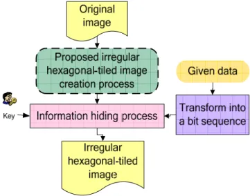
The proposed process of data hiding in irregular-hexagonal-tiled images is shown in Figure 1.1. According to the flowchart, first of all, we create an irregular- hexagonal-tiled image, which will be discussed thoroughly in Section 3.2. Second, we transform given data into a bit sequence which will be hidden. The given data might
be a watermark, a secret message, or any digital data which you want to transmit covertly. Third, we use a secret key to disarrange a bit sequence, and then conduct an information hiding process. A detailed discussion of the proposed method for data hiding in irregular-hexagonal-tiled images will be stated in Section 3.3.3.
The proposed process of data extraction from irregular-hexagonal-tiled images is shown in Figure 1.2. After checking the secret key and performing the proposed process of data extraction, we get embedded secret information from the irregular- hexagonal-tiled image. The proposed method for data extraction from irregular- hexagonal-tiled images will be thoroughly discussed in Section 3.3.4.
1.2.4 Brief Review of Adopted Methods for Mosaic
Images Creation
A method [17] of mosaic image creation is adopted in this study and a flowchart of it is shown in Figure 1.3. It can be divided into two parts. One is tile image database creation; the other is mosaic image generation. The first part is off-line in nature, and the other is on-line. We will describe the detail of the adopted method for mosaic image creation in Section 4.1.
Figure 1.2 Proposed process of data extraction from irregular-hexagonal-tiled images.
1.2.5 Brief Description of Proposed Method for
Creation of Tile-Overlapping Mosaic Images
and Information Hiding in Them
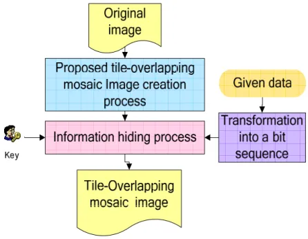
The proposed process of data hiding in tile-overlapping mosaic images is shown in Figure 1.4. According to the flowchart, first of all, we create a tile-overlapping mosaic image, which will be discussed thoroughly in Section 4.3. Second, we transform given data into a bit sequence which will be hidden. Third, we use a secret key to disarrange a bit sequence, and then conduct the information hiding process. A detailed discussion of information hiding in tile-overlapping mosaic images will be stated in Section 4.4.2. The proposed process of data extraction from tile-overlapping mosaic images is shown in Figure 1.5. After checking the secret key and performing the proposed process of data extraction, we can get secret information from the tile-overlapping mosaic image. The method will be thoroughly discussed in Section 4.4.3.
Figure 1.3 A flowchart of adopted mosaic image creation method [17].
Figure 1.4 Proposed process of data hiding in tile-overlapping mosaic images. Off Line
Image Database Creation
Extract color features
Represent features Image
Metadata table
On Line
Mosaic Image Generation Original
image
Divide original image into tiles
Get the best matching image for each tile
Mosaic image Extract color features
of each tile image
Put tile images together
DB Resize the image
Figure 1.5 Proposed process of data extraction from overlapping mosaic images.
1.2.6 Brief Description of Proposed Method for
Creation of Variable-Sized Mosaic Images and
Information Hiding in Them
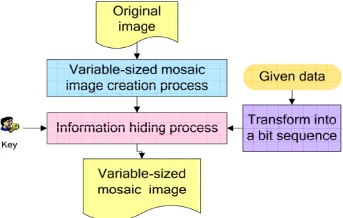
The process of data hiding in variable-sized images is illustrated in Figure 1.6. The data extraction process is an inverse version of the data hiding process as shown in Figure 1.7. We achieve the purpose of data hiding by changing the size of tile images in variable-sized mosaic images. For example, we use small blocks whose size is 16×16 pixels to represent bit 0 and big blocks whose size is 32×32 pixels to represent bit 1. Detailed descriptions of the proposed methods shown in these two flowcharts will be given in Chapter 5.
Figure 1.6 Proposed process of data hiding in variable-sized mosaic images.
Figure 1.7 Proposed process of data extraction from variable-sized mosaic images.
1.3 Contributions
In this study, several contributions have been made, which are described in the following.
1. A method to create irregular-hexagonal-tiled images is proposed.
2. A method to hide information into irregular-hexagonal-tiled images by modifying locations of two vertices and inner colors of hexagonal tiles is proposed.
3. Methods to embed secret messages and watermarks simultaneously into the hexagonal tiles in irregular-hexagonal-tiled images are proposed.
4. A method to extract information from irregular-hexagonal-tiled images by detecting locations of two vertices and inner colors of hexagonal tiles is proposed. 5. A method to generate tile-overlapping mosaic images is proposed.
6. A method to hide information into tile-overlapping mosaic images by changing the overlapping pixels of adjacent tile images is proposed.
7. A method to embed secret messages and watermarks simultaneously into the adjacent tile images in the tile-overlapping mosaic images is proposed.
8. A method to extract information from tile-overlapping mosaic images by detecting the degree of overlapping between adjacent tile images is proposed.
9. A method to generate variable-sized mosaic images is proposed.
10. A method to hide information into variable-sized mosaic images by modifying the sizes of tile images is proposed.
11. A method to extract information from variable-sized mosaic images by detecting the sizes of the tile images is proposed.
1.4 Thesis Organization
The remainder of this thesis is organized as follows. In Chapter 2, we review related works. In Chapter 3, the proposed methods for creation of irregular- hexagonal-tiled images, information embedding, and information extraction in irregular-hexagonal-tiled images are described. In Chapter 4, the proposed methods for creation of tile image database and tile-overlapping mosaic images, information embedding, and information extraction in tile-overlapping mosaic images are
described. In Chapter 5, we describe the proposed methods for creation of variable-sized mosaic images, information embedding, and information extraction in variable-sized mosaic images. Conclusions of our works as well as discussions on future works are included in Chapter 6.
Chapter 2
Review of Related Works
2.1 Previous Studies on
Non-photorealistic Rendering
Non-photorealistic rendering (NPR) is a new and developing domain in computer graphics in recent years. It can express more esthetic arts than traditional photorealistic rendering. Using computers to imitate skills of painters and painting styles, we can conduct painting and obtain results which seem to be painted by famous painters, and the working time is short. How to imitate and study painting skills by computers are the major goals of NPR. Most investigations on NPR concentrate on occidental art paintings. Only a few studies on Chinese painting styles are found in the NPR domain.
Guo, et al. [1] presented an approach to generating paintings on photographic images with the style encoded by example paintings and adopted representative brushes extracted from the example paintings as the painting primitives. Figure 2.1 shows the used brushes. An experimental result is shown in Figure 2.2. Their method can be divided into the following components: (1) brush library construction; (2) region segmentation; (3) grounding layer synthesis; (4) direction field construction; (5) brush painting; and (6) fusion with images.
Chen [2] presented an approach to automatic generation of pencil sketching with the effects of paper texture. An experimental result is shown in Figure 2.3. His method can be described as follows:
(1) histogram-based image subdivision into four layers (bright, grey, darker, darkest); (2) revised LIC (Line Integral Convolution) for pencil stroke synthesis on each layer,
except for the bright layer;
(3) center-off filtering for silhouette generation; (4) silhouette enhancement;
(5) fusion of sketching strokes in different layers, silhouettes, and enhanced parts, and paper texture.
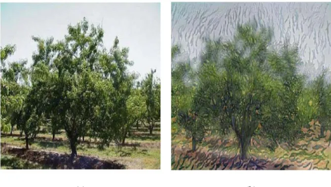
Baxter, et al. [3] presented a painting system with an intuitive haptic interface, which serves as a “semi-automatic” platform for users to create paintings interactively with computer systems. This framework allows artists to choose proper brushes from a wide selection, and also allows artists to mix and create an almost unlimited number of colors through a simple, unified interface as shown in Figure 2.5. Figure 2.4 shows some generated examples of strokes. Some artworks created using this system are shown in Figure 2.6. We show other experimental results in Figure 2.7. Figure 2.7 (a) is a watercolor image created by real-time simulation of a watery paint algorithm from Laerhoven and Reeth [4]. Figure 2.7 (b) is an image created from Hertzmann [5]. Figure 2.7 (c) is a computer-generated watercolor from [6]. Figure 2.7 (d) is an image created from Chen [7].
(a) (b)
Figure 2.1 The brushes selection process. (a) An input image: Olive Grove by Van Gogh. (b) Brushes selected from Van Gogh’s Olive Grove.
(a) (b)
Figure 2.2 An experimental result. (a) An original image. (b) An image created from Guo, et al. [1].
(a) (b)
Figure 2.4 Illustration of real brushes, model for each, and example strokes generated with each [3].
(a) (b)
Figure 2.5 Graphic user interface [3]. (a) The virtual canvas with the brush rack and a part of the palette. (b) The brush rack and the palette for color mixing.
(a) (b)
Figure 2.6 The artworks created using the system from [3]. (a) A painting by Rebecca Holmberg. (b) A painting by Lauren Adams.
(a) (b) (c)
Figure 2.7 Samples of computer-generator art images. (a) An image created from Laerhoven and Reeth [4]. (b) An image created from Hertzmann [5]. (c) A computer-generator watercolor from [6]. (d) An image created from Chen [7].
(d)
Figure 2.7 Samples of computer-generator art images. (a) An image created from Laerhoven and Reeth [4]. (b) An image created from Hertzmann [5]. (c) A computer-generator watercolor from [6]. (d) An image created from Chen [7]. (continued)
2.2 Previous Studies on Mosaic Images
Mosaic images are surface decorations composed of numerous small tiles, which are often of similar shapes or sizes, but in different colors. Tile mosaics appeared in Greek and Roman times over 2000 years ago, and are still widely used today. Creation of them is a new research topic in recent years.
Kojima, et al. [8] proposed a top-down approach that first generates a mosaic based on global features such as image gradations, and then incorporates local features into the underlying partition based on the global features. More specifically, they first constructed a quadrilateral mosaic using the global features, and then incorporated local features such as object silhouettes specified by users into the existing global mosaic by referring to the dual network of the mosaic partition. They proposed an effective algorithm organized in two phases as shown in Figure 2.8. Figure 2.9 is one of their experimental results.
region with a color sampled from the underlying image. Figure 2.10 is an experimental result. Obviously, the effects of edge features are not very good. Hausner [10] proposed a method to create tile mosaic images by utilizing centroidal voronoi diagrams, as shown in Figure 2.11. In Hausner [10], the method proposed by Hoff [11] is extended to draw a voronoi diagram efficiently, and Lloyd’s algorithm [12] was utilized to produce centroidal voronoi diagrams by moving each seed to the centroid of its voronoi region.
Figure 2.8 Steps in the proposed method from Kojima, et al. [8].
(a) (b) (c)
Figure 2.9 Experimental results from Kojima, et al. [8]. (a) An original image. (b) A mosaic image only with global features. (c) A mosaic image with both global and local features.
Figure 2.10 An experimental result by using Haeberli’s method [9].
2.3 Previous Studies on Information
Hiding Techniques
Many information hiding techniques have been proposed to embed data into a given media for various purposes. Information hiding in images mostly aims at taking the advantage of the weaknesses of the human visual system, for example, by changing the least significant bits of the pixels of a cover image to embed information [13]. The information embedded in an image can be used to protect the copyright of the image, verify the authenticity of the image, convey a secret message, and so on.
Researches on this topic can be classified into three approaches, namely, the spatial-domain approach, the frequency-domain approach, and the combination of them [14]. Ni, et al. [15] presented a novel reversible data hiding algorithm in the spatial domain by utilizing the zero or the minimum point of the histogram and slightly modified the pixel values to embed data. Cheng and Tsai [16] proposed a DCT-based method for embedding an invisible watermark by adjusting the magnitude relation of certain DCT coefficient pairs in the frequency domain. No matter what domains they belong to, most of these researches are based on pixel-wise or block-wise operations. Generally speaking, information hiding in the frequency domain is more robust than that in the spatial domain.
2.4 Previous Studies on Information
Hiding in Art Images
manipulate the four borders of tile images. The other is to modify the histogram of tile images. Hung [18] proposed two methods to hide information in art images. One is to embed data in the tile mosaic image by modifying the orientations, sizes, and textures of tile images. The other is to embed data in the stained glass image by cracking glasses slightly. Hsu [20] proposed three methods to hide information in art images. One is to embed data in digital puzzle images by modifying the orientations, sizes, and angles of the puzzle image. Another is to embed data in the pointillistic image by varying the RGB values of each color dot of the pointillistic image. The other is to embed data in the circular-dotted image by modifying the drawing order of the circular dots of the circular-dotted image. Some image mosaics created by Lin [17] are presented in Figure 2.12. Some tile mosaic images and stained glass images created by Hung [18] are shown in Figure 2.13. Some art images created by Hsu [20] are shown in Figure 2.14.
(a) (b)
Figure 2.12 Image mosaics created by Lin [17]. (a) A mosaic image of Lena. (b) A mosaic image of Albert Einstein.
(a)
(b)
Figure 2.13 Art images created by Hung [18]. (a) A tile mosaic image. (b) A stained glass image.
(a)
(b)
(c)
Figure 2.14 Art images created by Hsu [20]. (a) A digital puzzle image. (b) A digital pointillistic image. (c) A digital circular-dotted image.
Chapter 3
Creation of
Irregular-Hexagonal-Tiled Image for
Information Hiding
3.1 Overview of Proposed Method
Hsu [20] proposed a method to create a pointillistic image and embed data in it by varying the RGB values of each color dot in the pointillistic image. They used small circles to fill the image to create the effect of pointillism. The idea of the proposed method to be described subsequently comes from this study.
In geometry, there are only triangles, squares, and hexagons that can be repeated and combined closely to one another and do not produce holes or overlapping areas. In these shapes, a hexagon has the largest number of vertices. So, we decide to utilize a hexagonal tile to be the basic unit when we create an art image. We found that we can implement information hiding works by modifying the locations of pairs of two specific vertices and changing the inner colors of the hexagons. Because of the vertex location modifications, the hexagonal shape appears to be irregular. So, we name the resulting art image an irregular-hexagonal-tiled image. We will describe the image creation and the information hiding processes for such images in the following sections.
3.2 Proposed
Irregular-Hexagonal-Tiled Image
Creation Process
3.2.1 Idea of Image Creation Process
Because hexagons can be combined closely to one another with no overlapping areas and because the number of their vertices is the largest among the above-mentioned three shapes, we decided to use hexagonal tiles to create an art image, as mentioned previously. But we found that if all hexagonal tiles are uniform in shape, the created image will be too dull. We also found that a vertex is used simultaneously by every three neighboring hexagons. An illustration is shown in Figure 3.1, in which vertex4 is co-used by hexagonB, hexagonC, and hexagonE, and
vertex5 is co-used by hexagonA, hexagonB, and hexagonC. So, we may modify the
locations of every pair of such two specific vertices of the combined hexagonal tiles to create more vivid effect in the resulting image. An illustration of a hexagonal shape with vertex numbering is shown in Figure 3.2.
In the proposed vertex position modification, with Figure 3.2 as an illustration, we just modify the y coordinate of vertex4, and the x coordinate of vertex5. Figure 3.3
illustrates a result after modifying these two vertices in hexagonB.
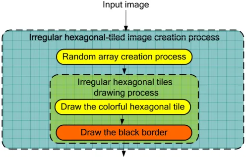
A flowchart of the process of creating irregular-hexagonal-tiled images is shown in Figure 3.4. The first step is to prepare two random arrays. The second is to modify the locations of two specific vertices of the hexagons corresponding to the random array, respectively. Third, we fill the inner region of the hexagonal tiles with the colors of the center of the original hexagon. Finally, we draw a black border for each tile. The detail of the creation process will be described in the next section.
Figure 3.1 The combined hexagonal-tiled image.
Figure 3.2 Vertex4 and vertex5 will be modified.
Input image
Random array creation process Irregular hexagonal tiles
drawing process
Draw the colorful hexagonal tile Draw the black border
Figure 3.4 A flowchart of the irregular-hexagonal-tiled image creation process.
3.2.2 Detail of Image Creation Process
The default width of the hexagonal tile is 6 pixels. The user can adjust the size, and input a desired value while executing the program. The detailed process is described as an algorithm as follows.
Algorithm 3.1: irregular-hexagonal-tiled image creation process.
Input: an image I and the width w of a hexagon. Output: an irregular-hexagonal-tiled image I'. Steps:
Step 1. Figure out how many hexagonal tiles will be drawn in an
irregular-hexagonal-tiled image by utilizing the input width w and the width of the original image.
Step 2. Create two random arrays RA1 and RA2.
Step 3. Modify the locations of the above-mentioned two specific vertices using RA1
3.3.
Step 4. Draw the resulting hexagonal tile at the upper leftmost corner of the output image I'.
Step 5. Conduct the same operations of Steps 1 through 3 to draw hexagonal tiles in a raster scanning manner.
In Step 2,we must create RA1 and RA2. We use Algorithm 3.2 below to describe
the creation process.
Also, in Step 4, drawing of a hexagonal tile is divided into two smaller steps as follows.
(1) Fill the inner region of the hexagonal tile with the colors of the center of the original hexagonal shape.
(2) Draw a black border around the hexagonal tile.
Algorithm 3.2: create a random array.
Input: the number N of hexagonal tiles which will be drawn. Output: a random array R.
Step 1. Set the array whose size is equal to N.
Step 2. Set each of the value of the array to be a random integer ranging from -2 to +2, using a suitable random number generator.
3.2.3 Experimental Results and Discussions
Figure 3.5(a) is an input image; Figure 3.5(b) is the corresponding irregular-hexagonal-tiled image created by applying the above irregular-hexagonal-tiled image creation process. Here, the input width of the hexagonal tile is 6. Figure 3.5(c) is the irregular-hexagonal-tiled image created from
Figure 3.5(a), but with the input width of the hexagonal tile being 8.
(a)
(b)
Figure 3.5 Experimental results. (a) An original image. (b) An irregular-hexagonal-tiled image with width=6. (c) An irregular-hexagonal-tiled image with width=8.
(c)
Figure 3.5 Experimental results. (a) An original image. (b) An irregular-hexagonal-tiled image with width=6. (c) An irregular-hexagonal-tiled image with width=8. (continued)
3.3 Proposed Method for Data Hiding in
Irregular-Hexagonal-tiled Images
3.3.1 Concept of Proposed Method
The main concept of the proposed method for data hiding in an irregular-hexagonal-tiled image is to adjust the locations of two specific vertices and modify the inner colors of the hexagonal tiles. We can hide thirteen bits into each hexagonal tile by these two techniques. First, we divide the bit stream sequence of a given secret message into several groups, each of which has thirteen bits. An example
is shown in Table 3.1. Second, we take the first two bits (part1) and check a “matching table” shown in Table 3.2 to get the variation of the y coordinate of vertex4
of the hexagonal shape to be drawn. Repeating these operations similarly, we can get the variation of the x coordinate of vertex5. Then, we divide the remaining 9 bits
(part3 to part5) into three parts, and transform them into decimal numbers. The decimal values are taken as the variations of the RGB values of the inner color of the hexagonal tile to be drawn, respectively. In short, we implement the desired information hiding work by utilizing these two techniques. The details will be stated clearly in Section 3.3.3.
Table 3.1 Components of hiding bits of a bit stream sequence of a given message.
12 11 10 9 8 7 6 5 4 3 2 1 0 bits order
B G R vertex5 vertex4
modified part part5 part4 part3 part2 part1 part
number
Table 3.2 A matching table for specifying vertex position variations.
Hiding bits Variation
00 -2 01 -1 10 +1 11 +2
3.3.2 Data Combination and Disarrangement
Processes
We assume, as done in the information paradigm that the secret information may be extracted by people who know the algorithm, so it is necessary to utilize a secret key to disorder the secret information before embedding it. The details of the data combination and disarrangement processes are described as an algorithm as follows.
Algorithm 3.3: data combination and disarrangement processes.
Input: a bit sequence of a secret message Mesi, a bit sequence of a watermark Wateri,
and a bit sequence of a secret key Ki.
Output: a randomized bit sequence of the combination of the inputs Mesi and Wateri.
Steps:
Step 1. Create an empty array, Data, whose size is equal to that of Mesi plus Wateri.
Step 2. Arrange the elements of Mesi into Data in order and append the elements of
Wateri into Data in order at the end of Mesi.
Step 3. Use the secret keyKi to create a random binary array, Key, whose size is equal
to that of Data.
Step 4. Apply the exclusive-OR operator to Data and Key bit by bit to obtain a randomized bit sequence, DDatai, combining the secret message and the
watermark.
3.3.3 Data Hiding Process
A flowchart of the data hiding process is shown in Figure 3.6. First, we derive a randomized Datai, denoted as DDatai, from the inputs Mesi and Wateri, using
size of thirteen, and divide each of them further into five parts. An example is shown in Table 3.1. The first and the second parts specify the y and x coordinate variations of vertex4 and vertex5 of the hexagonal tile to be drawn, respectively. The other three
parts are used as the augmentative values of the RGB values of the center colors of the hexagonal tiles in the original image. Finally, we apply the proposed irregular-hexagonal-tiled image creation process described previously. Then we can get a stego-irregular-hexagonal-tiled image. The detail of the data hiding process is described as an algorithm below.
Algorithm 3.4: data hiding in an irregular-hexagonal-tiled image.
Input: an image I, a secret message Mes, a watermark Water, and a secret key K. Output: a stego-irregular-hexagonal-tiled image I'.
Steps:
Step 1. If the RGB values of any pixel of I are smaller than (8, 8, 8), respectively, we replace them with the RGB values (8, 8, 8). Set the RGB values of each pixel in I to be multiples of eight. That is, compute
new value r (denoted as Nvr) = (original r value / 8) × 8; new value g (denoted as Nvg)= (original g value / 8) × 8; new value b (denoted as Nvb)= (original b value / 8) × 8.
Step 2. Convert the secret message size into a bit stream sequence, and then use Algorithm 3.5 to embed it in the first hexagonal tile.
Step 3. Convert the watermark size into a bit stream sequence, and then use Algorithm 3.5 to embed it in the second hexagonal tile.
Step 4. Convert Mes and Water into bit sequences Mesi and Wateri, respectively.
Step 5. Use the secret key K, Mesi, and Wateri to derive a randomized bit stream
Step 6. Divide S into several substrings, each of which has a size of thirteen.
Step 7. Use Algorithm 3.5 below to construct a stego-hexagonal tile in a raster scanning manner until all substrings are handled.
Algorithm 3.5: data hiding in a hexagonal tile.
Input: a hexagonal tile T and a binary substring s whose size is thirteen. Output: a stego-hexagonal-tile T’.
Steps:
Step 1. Take the fist part of s to check the matching table which is shown in Table 3.2, and compute the new y coordinate of its vertex4 as the found variation in the
table plus the original y coordinate of the vertex in T.
Step 2. Take the second part of s to check the matching table, and compute the new x coordinate of its vertex5 as the variation found in the table plus the original x
coordinate of the vertex in T.
Step 3. Transform the third part of s into a decimal integer, denoted as addR, and set the final value r equal to addR plus Nvr mentioned previously.
Step 4. Transform the fourth part of s into a decimal integer, denoted as addG, and set the final value g equal to addG plus Nvg.
Step 5. Transform the fifth part of s into a decimal integer, denoted as addB, and set the final value b equal to addB plus Nvb.
Step 6. Draw the hexagonal tile with a black border.
3.3.4 Data Extraction Process
The main concept of the data extraction process is to figure out the variations of the locations of every two specific vertices and the inner colors of the hexagonal tiles, and compose the data to recover the originally embedded secret message in a given
stego-image.
In vertex4, we only modified the y coordinate in the data embedding process and
we know the original y coordinate. So, we just sequentially check the possible locations of vertex4, and then check the matching table shown in Table 3.2 to get the
hidden bits. In vertex5, the situation is almost the same as in vertex4. The only
difference is that the modified coordinate of vertex5 is the x coordinate. In this way,
we can get four bits from vertex4 and vertex5. Then we proceed to get the RGB values
of the inner colors of the hexagonal tiles and acquire the remainders of the RGB values by dividing them by eight, respectively. Finally, we convert in order the three remainders into a bit sequence whose number is 9. The data extraction process is completed after concatenating all extracted bits in order. The process is described as an algorithm below.
Algorithm 3.6: data extraction from an irregular-hexagonal-tiled image.
Input: a stego-irregular-hexagonal-tiled image I'.
Output: a randomized bit stream sequence, the message size, and the watermark size. Steps:
Step 1. Find the secret message size by the following way.
1.1. Use Algorithm 3.7 to extract a bit stream sequence from the first hexagonal tile shown in Figure 3.7.
1.2. Convert the bit stream sequence into a decimal value. 1.3. Take the decimal value as the desired secret message size. Step 2. Find the watermark size by the following way.
2.1. Use Algorithm 3.7 to extract a bit stream sequence from the second hexagonal tile shown in Figure 3.7.
2.3. Take the decimal value as the desired watermark size.
Step 3. Use Algorithm 3.7 to extract a bit stream sequence from each of the hexagonal tiles which are marked by the purple arrows shown in Figure 3.7 in order.
Step 4. After all the hexagonal tiles are processed, compute the desired randomized bit stream sequence by concatenating all the sequences obtained previously in order.
Algorithm 3.7: data extraction from an irregular-hexagonal tile.
Input: an irregular-hexagonal tile T.
Output: a bit stream sequence whose size is thirteen. Steps:
Step 1. Find the new y coordinate of vertex4 of T.
Step 2. Subtract the original y coordinate from the new y coordinate derived in Step 1 to get an integer.
Step 3. Take the integer to check the matching table to get two bits. Step 4. Find the new x coordinate of vertex5 of T.
Step 5. Subtract the original x coordinate from the new x coordinate derived in Step 4 to get an integer.
Step 6. Take the integer to check the matching table to get two message bits. Step 7. Take the RGB values from the center of T.
Step 8. Calculate the remainders of the RGB values by dividing the RGB values by eight, respectively.
Step 9. Convert the three values obtained in the last step into a bit stream sequence with nine bits.
3.3.5 Data Recovery and Separation Processes
The data recovery and separation processes are the inverse version of the data combination and disarrangement processes which are proposed in Section 3.3.2. They are described as an algorithm below.
Algorithm 3.8: data recovery and separation processes.
Input: a randomized bit stream sequence DDatai, a secret key K, and a secret
message size M.
Output: a secret message Mesi and a watermark Wateri.
Steps:
Step 1. Use the secret key K to create a binary array, Key, whose size is equal to that of DDatai.
Step 2. Apply the exclusive-OR operator to DDatai and Key, resulting in the original bit
sequence Datai of the combination of the inputs Mesi and Wateri.
Step 3. Take the first M bits from Datai as Mesi, and the other part as Wateri.
3.3.6 Experimental Results and Discussions
Figure 3.8 shows some experimental results of data hiding in an irregular-hexagonal-tiled image. Figure 3.8 (a) is an irregular-hexagonal-tiled image with the secret message, “Lena 是一位瑞典女士 Lena Sjooblom 的照片,” and the watermark, Figure 3.8 (c), embedded. Figure 3.8 (b) is the secret message extracted from Figure 3.8 (a) with a correct key. Figure 3.8 (d) is the watermark extracted from Figure 3.8 (a) with a correct key. Figure 3.8 (e) shows the extraction results from
Figure 3.8 (a) with a wrong key.
Figure 3.6 A flowchart of the data hiding process in the irregular-hexagonal-tiled image.
(a)
(b)
(c) (d)
(e)
Figure 3.8 Experimental results of data hiding in an irregular-hexagonal-tiled image. (a) An irregular-hexagonal-tiled image with the secret message and watermark (c) embedded. (b) The secret message extracted from (a) with a correct key. (d) A watermark extracted from (a) with a correct key. (e) The extraction results from (a) with a wrong key.
Chapter 4
Creation of Tile-Overlapping Mosaic
Images for Information Hiding
4.1 Review of Traditional Mosaic Image
Creation Process
4.1.1 Mosaic Images Creation Process
A method [17] of mosaic image creation is adopted in this study and a flowchart of it is shown in Figure 4.1. The creation process can be divided into two major stages. One is construction of a tile image database and the other is generation of mosaic images. The first stage is conducted off-line, and the second on-line. A tile image database is established prior to the mosaic image generation process. Some metadata of the tile images need be built through a feature extraction process and such metadata are mainly the descriptions of the color distributions of the tile images. We will describe how to construct a tile image database in Section 4.1.2. The mosaic image generation process aims to divide an input image into numerous tiles based on a given tiling style. Additionally, a similarity measure is employed to get the best matching image from the tile image database for each tile. Finally, we compose all of the best-matching tile images together to produce a mosaic image. The detail of the process of mosaic image generation is described as an algorithm as follows.
Algorithm 4.1: mosaic image generation process.
Input: an image I, a tile image database DB, and a tiling style S. Output: a mosaic image.
Steps:
Step 1. Divide I into tiles according to S.
Step 2. Get the best matching tile image from DB for each target tile T according to the following rule.
2.1. Calculate the average colors of T.
2.2. Represent the colors as a one-dimension feature vector Vtarget.
2.3. Get a feature vector Vtile from the metadata of DB.
2.4. Calculate the distance between Vtile and Vtarget according to the following
formula where | • | means the Euclidean distance:
D = |Vtarget – Vtile|2.
2.5. Find the smallest D after testing all Vtile from DB.
2.6. Get the best matching tile image from DB accordingly.
Step 3. Compose all of the tile images together according to S to produce a mosaic image.
4.1.2 Tile Image Database Construction
Tile image database construction is the first step for mosaic image creation and it plays an important role in the entire process. We utilize a database to store the extracted color features and this can accelerate the computation of searching the best matching tile image. We accomplish tile image database construction using the following algorithm.
Algorithm 4.2: tile image database construction.
Input: a set of images, S = {I1, I2, …, In}.
Output: a set of tile images, O = {T1, T2, .., Tn}, for use as the tile image database and
an associated metadata table M. Steps:
Step 1. Resize each Ii, i = 1, 2, …, n, to a pre-defined tile image size, resulting in a
new image Ti.
Step 2. Calculate the average color of Ti in each of the RGB channels.
Step 3. Represent the average colors as a one-dimension feature vector Vi with three
elements Ri, Gi, and Bi.
Step 4. Add Vi to M.
Step 5. Save O and M in the storage as the desired output.
In this study, the pre-defined tile image size is chosen to be 32×32 pixels. After resizing an input image, we extract and represent the color features extracted from it as a vector. In the RGB color model, we use red, green, and blue as the three primary colors. A metadata table is built by combining all the feature vectors derived from Step 4.
4.1.3 Similarity Measure for Tile Matching
In the above algorithm, we see that the adopted similarity measure between a target image and a tile image from a database is based on the RGB color model. A feature vector is obtained by calculating the average color of a tile image in each of the RGB channels. In the mosaic image generation process, an image from the tile image database is considered to be the most similar to a given target image if the value of the similarity measure based on the Euclidean distance between the two
feature vectors is the smallest.
Figure 4.1 A flowchart of adopted mosaic image creation method [17].
4.2 Overview of Proposed Method
Traditional mosaic images contain numerous tile images which are of uniform sizes, and the arrangement of them is usually regular. However, we want to create new-styled mosaic images in this study by modifying the regular arrangement style of the tile images. An illustration of the proposed arrangement scheme is shown in Figure 4.2(b). Additionally, during the image creation process, we desire also to
Off Line
Image Database Creation
Extract color features
Represent features Image
Metadata table
On Line
Mosaic Image Generation Original
image
Divide original image into tiles
Get the best matching image for each tile
Mosaic image Extract color features
of each tile image
Compose all the tile images together
DB Resize the image
achieve the data hiding application by utilizing the arrangement scheme. We will state how to create the mosaic image and explain how we carry out the data hiding operation during the image creation process in the following sections.
4.3 Proposed Tile-Overlapping Mosaic
Image Creation Process
4.3.1 Idea of Image Creation Process
Our inspiration of this topic of study comes from the creation process of the circular-dotted image proposed by Hsu and Tsai [19]. The main concept of the creation process of the circular-dotted image is to utilize the drawing order of the circular-dots in a circular-dotted image. We imitate their overlapping scheme. However, the basic unit of our ‘painting’ here is a tile image. The arrangement of tile images in a traditional mosaic image is shown in Figure 4.2(a) and the proposed arrangement of tile images in the proposed new-styled mosaic image is shown in Figure 4.2(b). The traditional arrangement is regular, while the proposed arrangement is irregular. In the traditional arrangement, we know in advance the location of each tile image. However, in the proposed new arrangement, we do not know the location of each tile image beforehand because we randomize the locations of each tile. The randomization is controlled by the use of a random number generator. So, the tile arrangements are unfixed in appearance, thus yielding a more vivid effect in the resulting image. However, this brings a problem. That is, due to irregular overlapping of the tiles, holes between adjacent tiles will be created and might block the data extraction process conducted later. So, how to avoid causing this hole-creation
problem during the image creation process is a critical issue. A solution proposed in this study will be described later. On the other hand, the randomized tile overlapping degree is fixed to be in a specific range, taken to zero to seven pixels in this study. We utilize such tile overlapping degrees to implement the data hiding work. More specifically, a tile overlapping degree of n pixels is used to embed a 3-bit message data of the value n. For example, if the message to be embedded is 1012 = 510, then we
let a tile image to overlap its preceding one either in the horizontal or vertical direction for 5 pixels to accomplish the embedding purpose. The image creation and data hiding processes are stated in the following.
4.3.2 Detail of Image Creation Process
In this section we show how to create a tile-overlapping mosaic image. The major steps are as follows.
(1) Construct a tile image database.
(2) Process the input image in the following order: the first column, the first row, and then the inner tiles.
(3) In the first column, draw one by one the best-matching tile images in such a way that the current one overlaps randomly the bottom side of the preceding one.
(4) In the first row, perform works similar to the last step but with the overlapping being on the right side of the preceding tile.
(5) Draw the inner tiles in a raster scan order in such a way that the current tile overlaps, in a random way, both the right side of the left tile and the bottom side of the upper one.
the tile image database, which is most “similar” to the image part appearing at the same location (called target image subsequently) in the input image (called cover
image in the sequel). Also in the last step above, the random overlappings there, as
mentioned previously, might create holes, which we want to eliminate. A technique to achieve this purpose is to move the tile to be drawn toward the left or upper direction
pixel by pixel until the hole disappears. More details of the process are described as an
algorithm below.
Algorithm 4.3: creation process of tile-overlapping mosaic image.
Input: a cover image I; a tile image database DB with each image being of the size
SZ× SZ with SZ being a given integer; a similarity measure SM, and a random
number generator F for integers in the range of 0 through 7. Output: a tile-overlapping mosaic image Im for I.
Steps:
Step 1. Create the first column of Im in the following way:
1.1. Crop the upper-leftmost SZ×SZ subimage of I and take it to be the target image Tar00.
1.2. Search DB for the tile image Bmt00 which matches Tar00 the best according to
the given similarity measure SM.
1.3. Draw Bmt00 in Im at the same location as that of Tar00 with a black border.
1.4. Generate a random integer number RN in the range of 0 to 7 by F.
1.5. Crop as a target image Tar0j from I an SZ×SZ image right below the preceding
target image Tar0(j-1) but with RN-pixel overlapping.
1.6. Search DB for the tile image Bmt0j which best matches Tar0j according to SM.
1.7. Draw Bmt0j in Im at the same location as that of Tar0j with a black border.
Step 2. Process the first row of Im in a similar way to Step 1 except that the
overlapping is on the right side of the preceding tile image.
Step 3. Process the inner tiles of Im in a raster scan order in the following way:
3.1. Generate by F two random integer numbers RN1 and RN2 ranging from 0 to 7.
3.2. Derive the position of Tarij using RN1 and RN2, which is to the right of the
horizontally preceding target image Tar(i-1)j in Im and below the vertically
preceding target image Tari(j-1) with an RN1-pixel horizontal overlapping as
well as an RN2-pixel vertical overlapping.
3.3. Check by the following way if a hole like either case shown in Figure 2 is created by Tarij in the last step.
Case 1:
1a. the vertically preceding target image Tari(j-1) has its upper boundary higher
than that of the upper-left neighboring target image Tar(i-1)(i-1); and
1b. there is a gap between the upper boundary of Tar(i-1)j and the lower
boundary of Tari(j-1); and
1c. there is a gap between the right boundary of Tar(i-1)(j-1) and the left
boundary of Tarij.
Case 2:
2a. the vertically preceding target image Tari(j-1) has its upper boundary lower
than that of the upper-left neighboring target image Tar(i-1)(i-1);
2b. there is a gap between the right boundary of Tar(i-1)j and the left boundary
of Tari(j-1);
2c. there is a gap between the lower boundary of Tar(i-1)(j-1) and the upper
boundary of Tarij.
If a hole of Case 1 is created, move Tarij to the left until the hole disappears,
Case 2 is created, move Tarij upward until the hole disappears, and crop an
SZ×SZ target image from I at the new position as Tarij
3.4. Search DB for the tile image Bmtij which best matches Tarij according to SM.
3.5. Draw Bmtij in Im at the same location as that of Tarij with a black border.
3.6. Repeat Steps 3.1 through 3.6 until all the inner tiles of Im are processed.
(a) (b) Figure 4.2 Tile arrangements. (a) The arrangement of the traditional tile images. (b) The proposed
arrangement of tile images.
(a) (b) Figure 4.3 The creation process may cause a hole by the illegal arrangement of Tilei,j. (a) Case 1. (b)
Case 2.
4.3.3 Experimental Results and Discussions
All the mosaic images of our experimental results were generated by using the tile image database with about 1900 images. The hiding capacity is about three
thousand bytes. Figure 4.4(a) is an input image. Figure 4.4(b) is the resulting tile-overlapping mosaic image created from Figure 4.4(a) by applying the tile-overlapping mosaic image creation process in Section 4.3.2. Figure 4.4(c) is an image composed of several tile images of the red region in Figure 4.4(b). Figure 4.4(d) is the resulting tile-overlapping mosaic image with white holes.
(a)
(b)
Figure 4.4 Experimental results. (a) An original image. (b) A tile-overlapping mosaic image. (c) Enlarged image from the red region of (b). (d) A tile-overlapping mosaic image with white holes.
(c)
(d)
Figure 4.4 Experimental results. (a) An original image. (b) A tile-overlapping mosaic image. (c) Enlarged image from the red region of (b). (d) A tile-overlapping mosaic image with white holes. (continued)
4.4 Proposed Method for Data Hiding in
Tile-Overlapping Mosaic Images
4.4.1 Concept of Proposed Method
The main concept of the data hiding process in a tile-overlapping mosaic image is to utilize the overlapping degree of every pair of adjacent tile images in a tile-overlapping mosaic image.
Mesi and a bit sequence of a watermark Wateri. By applying the data combination and
disarrangement processes proposed in Section 3.3.2, we can derive a bit sequence of disordered data DDatai. Second, we perform the tile overlapping scheme which will
be discussed in Section 4.4.2 to deal with DDatai. Finally, we utilize the derived
overlapping degree to create a tile-overlapping mosaic image by applying the image creation process proposed in Section 4.3.2.
Referring to the concept of the data extraction process shown in Figure 4.5(b), by applying the overlapping detection process, which will be proposed in Section 4.4.3, we can extract DDatai from a stego-tile-overlapping mosaic image. Finally, by
applying the data recovery and separation processes proposed in Section 3.3.5, we can derive the embedded Mesi and Wateri.
4.4.2 Data Hiding Process
Before performing the data hiding process in a tile-overlapping mosaic image, we process the cover image in advance. If the RGB values of a pixel in the cover image are (0, 0, 0) or (1, 1, 1), we replace them with the RGB values (0, 0, 1). The two colors (0, 0, 0) and (1, 1, 1) are reserved for special purposes as described in the following. This process of color changes is necessary for the data extraction process.
The major step of the proposed data hiding process is to take sequentially 3-bit sequences from the prefix of a randomized version of the secret message as overlapping degree values and run the proposed image creation process (Algorithm 4.3) to embed them into the cover image.
In case a hole is created using a certain overlapping degree, we have to eliminate the hole by adjusting the horizontal or vertical position of the tile with respect to its left or upper tile image, respectively, as mentioned previously. But then the overlapping degree is changed, meaning that the originally embedded 3-bit sequence
![Figure 2.5 Graphic user interface [3]. (a) The virtual canvas with the brush rack and a part of the palette](https://thumb-ap.123doks.com/thumbv2/9libinfo/8754977.206684/25.892.188.708.390.662/figure-graphic-user-interface-virtual-canvas-brush-palette.webp)
![Figure 2.9 Experimental results from Kojima, et al. [8]. (a) An original image. (b) A mosaic image only with global features](https://thumb-ap.123doks.com/thumbv2/9libinfo/8754977.206684/28.892.133.738.841.1054/figure-experimental-results-kojima-original-mosaic-global-features.webp)
![Figure 2.11 An image created from Hausner [10].](https://thumb-ap.123doks.com/thumbv2/9libinfo/8754977.206684/29.892.163.734.554.1085/figure-image-created-hausner.webp)
![Figure 2.12 Image mosaics created by Lin [17]. (a) A mosaic image of Lena. (b) A mosaic image of Albert Einstein](https://thumb-ap.123doks.com/thumbv2/9libinfo/8754977.206684/31.892.146.747.536.995/figure-image-mosaics-created-mosaic-mosaic-albert-einstein.webp)
![Figure 2.14 Art images created by Hsu [20]. (a) A digital puzzle image. (b) A digital pointillistic image](https://thumb-ap.123doks.com/thumbv2/9libinfo/8754977.206684/32.892.138.736.567.955/figure-images-created-digital-puzzle-image-digital-pointillistic.webp)