IEEE MICROWAVE AND WIRELESS COMPONENTS LETTERS, VOL. 15, NO. 12, DECEMBER 2005 841
Modified Parallel-Coupled Filter With Two
Independently Controllable Upper
Stopband Transmission Zeros
Ching-Ku Liao and Chi-Yang Chang, Member, IEEE
Abstract—A microstrip cross-coupled filter with two
indepen-dently controllable transmission zeros on upper stopband is pre-sented. The initial filter structure is a conventional Chebyshev-re-sponse parallel-coupled filter that can be easily realized by the an-alytical method. The newly proposed coupling/shielding lines can effectively control the cross and main couplings without changing the original filter layout. This approach allows a designer to elim-inate the tedious segmentation method, which is usually used to establish the relation between the coupling coefficient and physical distance between resonators. A three-order filter is designed and fabricated for demonstration.
Index Terms—Cross-coupled, microstrip filters, transmission
zeros.
I. INTRODUCTION
T
HE cross-coupled microstrip filters have been extensively studied in recent years. Research efforts are focused mainly on two aspects. One is in finding a new shape for a resonator. Another is developing novel synthesis methods, which enable a designer to arrange resonators in different ways to achieve an advanced response, such as a generalized Chebyshev response. Resonators with different shape, such as loop [1], hairpin [2], and patch [3] have been arranged in spe-cific topologies for improving the selectivity or in-band group delay of filters. Some widely applied topologies are cascade quadruplet (CQ) and cascade trisection (CT) [4]. Besides CQ and CT, novel synthesis methods have lead to novel topolo-gies containing couplings of source/load to multiresonator [5], [6]. In short, novel physical structures accompanied with advanced synthesis methods have enriched the possibilities of a microstrip filter.However, the designs of cross-coupled filters are not as straightforward as conventional ones such as parallel-coupled filter, end-coupled filter, etc. In the design of a cross-coupled filter, there are no explicit expressions to relate synthesized electrical parameters to physical dimensions of a filter. There-fore, when designing a cross-coupled filter, the first step is to synthesize a coupling matrix. Then, use the segmentation method to relate coupling strength to the physical distance
Manuscript received June 27, 2005; revised August 11, 2005. This work was supported by the National Science Council of Taiwan, R.O.C., under Grant NSC 94–2752–E-09–003–PAE. The review of this letter was arranged by Associate Editor J.-G. Ma.
The authors are with the Department of Communication Engineering, National Chiao-Tung University, Hsinchu 300, Taiwan, R.O.C. (e-mail: [email protected]).
Digital Object Identifier 10.1109/LMWC.2005.860017
Fig. 1. (a) Conventional parallel-coupled filter. (b) The modified filter. (c) The coupling route of the modified filter.
between resonators [1]. The drawback of the design procedures is that once the size of the resonator changes, designers must redo the segmentation method to find physical dimensions of filters. Moreover, since the segmentation method can only provide approximated dimensions of the filter, fine tunings are always needed.
To skip the tedious designing routine of the segmentation method, we propose an easy designing procedure to realize a filter with two upper stopband transmission zeros. The basic
842 IEEE MICROWAVE AND WIRELESS COMPONENTS LETTERS, VOL. 15, NO. 12, DECEMBER 2005
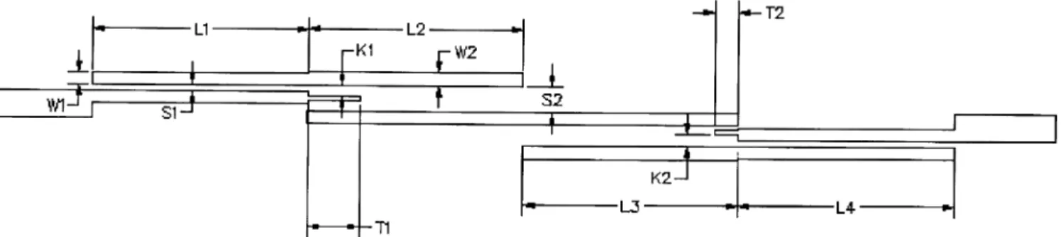
Fig. 2. Layout of the fabricated filter (in mil). L1= 354; L2 = 354; L3 = 354; L4 = 354; S1 = 11; S2 = 35; W1 = 19; W2 = 21; K1 = 19; K2 = 20; T1 = 87; T2 = 39. The line with of coupling/shielding lines is 8 mil.
structure of the proposed filter utilizes the conventional mi-crostrip parallel-coupled filter [7], as shown in Fig. 1(a), to serve as the initial design. Then, vertically flip feeding lines of the source and the load, as shown in Fig. 1(b). As described by Chang and Itoh [8], the physical dimensions keep the same during flipping. Next, adding the proposed coupling/shielding lines at the ends of input and output feed lines, as depicted in Fig. 1(b). Fig. 1(c) shows the coupling diagram of Fig. 1(b) and the coupling elements can be optimized and fine-tuned by the method proposed in [9]. The proposed layout of the filter is somewhat similar to those of [8]. Nevertheless, the strengths of couplings and in the filters described in [8] are extremely weak and not taken into account during filter design procedures. In this letter, we introduce these coupling/shielding lines to control the strength of and , which makes it possible to independently control two transmission zeros in the upper stopband.
II. CIRCUITDESCRIPTION ANDDESIGNFEASIBILITY
The design procedures start with the conventional microstrip parallel-coupled filter. Following easy design procedures, di-mensions of a Chebyshev-response parallel-coupled filter as shown in Fig. 1(a) can be obtained. Then, vertically flip feeding lines of the source and the load with respect to resonator “1” and resonator “n,” respectively. Note that the gap spacing in Fig. 1(a) is identical to that in Fig. 1(b). During practical layout, designers may shorten resonators in advance to prevent the feed lines from directly connecting to resonator “2” or resonator “ ” if needed.
To introduce two independently controllable transmission zeros on the upper stopband, the design procedures can be started with the Chebyshev-response coupling matrix and perturb it by introducing cross couplings and to form two trisection blocks as shown in Fig. 1(c). During this procedure, it is found that in order to keep equal ripple in-band response, the strength of and must be decreased and the frequencies of the resonators need to be adjusted. Therefore, a suitable manner to simultaneously introduce cou-plings and , and decrease the strength of and is needed. The coupling/shielding lines shown in Fig. 1(b) seem to be a perfect candidate. The coupling/shielding lines can introduce couplings and , and decrease the strength of and by shielding part of their coupling gaps. Practically speaking, the length, width, and
vertical position of the coupling/shielding line can be adjusted. Here, we fix the line width and adjust the line length and vertical position. The vertical position of the coupling/shielding line has little effect on shielding but has a strong influence on cross-coupling. In Chebyshev-response parallel-coupled filters, the relations and always hold, which makes it possible to add a coupling/shielding line at the end of the feed lines. Another merit of the parallel-coupled filter structure is that when adjusting the length of the resonator to align the resonant frequencies, the coupling between resonators is nearly unchanged. The feasibility of nearly independently tuning the coupling and frequencies makes it easy to implement the asynchronous tuned filter as that in Fig. 1(c).
III. DESIGNEXAMPLE ANDEXPERIMENT
To show the feasibility of the proposed structure, an example is given below. The center frequency, in-band return loss, and fractional bandwidth of the filter are chosen to be 5 GHz, 20 dB, and 5%, respectively. The filter is built on a Rogers RO4003 substrate with 3.58, thickness 20 mil, and
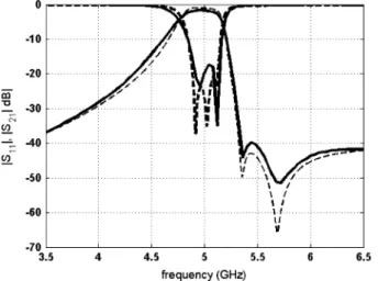
0.0021. The initial dimensions of the parallel-coupled filter are obtained by the analytical method described in [7]. The cou-pling/shielding lines with length and are added at the ends of feed lines as shown in Fig. 2, to introduce two transmission zeros separately. Two prescribed transmission zeros are located at 5.35 and 5.7 GHz, respectively. The initial value of and can be arbitrarily set at 50 mil and 30 mil. The -pa-rameter of the filter is then obtained with the help of the commer-cial EM simulator Sonnet [10]. Next, the method described in [9] can be used to extract the coupling matrix from the simulated -parameters. The physical dimensions of the filter are then adjusted according to the extracted coupling matrix to match the prescribed response [11]. After a total of five EM-simula-tion, matrix extracEM-simula-tion, and physical parameter adjusting loops, one can get the simulated results as shown in Fig. 3. The mea-sured results are also shown in Fig. 3 for comparison. The corre-sponding physical sizes are shown in Fig. 2. The correcorre-sponding coupling matrix is extracted as follows:
LIAO AND CHANG: MODIFIED PARALLEL-COUPLED FILTER 843
Fig. 3. Simulated and measured responses. Solid line: measured results. Dashed lines: EM simulated results.
Fig. 4. EM simulated results of three different cases. The dimensions of the simulated filter are the same as these shown in Fig. 2 exceptT 2 is set to different values.
It should be emphasized that the filter shown in Fig. 2 has exactly the same layout as the initial design except for two cou-pling/shielding lines. Therefore, designers can easily realize this filter through trial and error without the use of the matrix ex-tracting procedure.
It is mentioned in Section II, that the introduction of the cou-pling/shielding lines in this manner can effectively adjust the transmission zeros with slight perturbation of the passband
re-turn loss. To demonstrate the merits of easy tuning of the pro-posed structure, three EM simulations are taken in which the length of the coupling/shielding line 2 are set to 14, 24, and 39 mil, respectively, while the other dimensions are the same as those given in Fig. 2. From the EM simulated results shown in Fig. 4, it is obvious that the transmission zero can be tuned over a wide range with negligible change in the passband return loss.
IV. CONCLUSION
We have proposed a modified parallel-coupled-line filter with two independently controllable transmission zeros in the upper stopband. The initial dimensions of the modified filter are sim-ilar to conventional ones, thus, the tedious segmentation method is not needed. Trimming the positions and lengths of proposed coupling/shielding lines, two independent transmission zeros can be easily implemented. The systematic method and suitable physical structure makes it possible to efficiently design a filter with proper response.
REFERENCES
[1] J. S. Hong and M. J. Lancaster, “Couplings of microstrip square open-loop resonators for cross-coupled planar microwave filters,” IEEE Trans. Microw. Theory Tech., vol. 44, no. 11, pp. 2099–2109, Nov. 1996. [2] , “Cross-coupled microstrip hairpin-resonator filters,” IEEE Trans.
Microw. Theory Tech., vol. 46, no. 1, pp. 118–122, Jan. 1998. [3] J. S. Hong and S. Li, “Dual-model microstrip triangular patch resonators
and filters,” in IEEE MTT-S Int. Dig., Jun. 2003, pp. 1901–1904. [4] J. S. Hong and M. J. Lancaster, Microstrip Filters for RF/Microwave
Applications. New York: Wiley, 2001.
[5] J. R. Montejo-Garai, “Synthesis of filters with transmission zeros at real frequencies by means of trisections including source/load to resonator coupling,” Electron. Lett., vol. 36, no. 12, pp. 1629–1630, Sep. 2000. [6] S. Amari, U. Rosenberg, and J. Bornemann, “Adpative synthesis and
design of resonator filters with source/load-multi-resonator coupling,” IEEE Trans. Microw. Theory Tech., vol. 50, no. 8, pp. 1969–1978, Aug. 2002.
[7] S. B. Cohn, “Parallel-coupled transmission-line-resonator filters,” IRE Trans. Microw. Theory Tech., vol. 6, pp. 223–231, Apr. 1958. [8] C.-Y. Chang and T. Itoh, “A modified parallel-coupled filter structure
that improves the upper stopband rejection and responsed symmetry,” IEEE Trans. Microw. Theory Tech., vol. MTT-39, no. 2, pp. 310–314, Feb. 1991.
[9] C.-K. Liao and C.-Y. Chang, “Design of micorstrip quadruplet filters with source-load coupling,” IEEE Trans. Microw. Theory Tech., vol. 53, no. 7, pp. 2302–2308, Jul. 2005.
[10] Em User’s Manual, Sonnet Software, Inc., Liverpool, NY, 2004. [11] P. Harscher, E. Ofli, R. Vahldieck, and S. Amari, “EM-simulator based
parameter extraction and optimization technique for microwave and mil-limeter wave filters,” in IEEE MTT-S Int. Dig., 2002, pp. 1113–1116.