Efficient Hierarchical Motion Estimation Algorithm
and Its VLSI Architecture
Bing-Fei Wu, Senior Member, IEEE, Hsin-Yuan Peng, Student Member, IEEE, and Tung-Lung Yu
Abstract—This paper addresses the development and hardware implementation of an efficient hierarchical motion estimation algo-rithm, HMEA, using multiresolution frames to reduce the compu-tational complexity. Excellent estimation performance is ensured using an averaging filter to downsample the original image. At the smallest resolution, the least two motion vector candidates are se-lected using a full-search block matching algorithm. At the middle level, these two candidate motion vectors are employed as the center points for small range local searches. Then, at the original reso-lution, the final motion vector is obtained by performing a local search around the single candidate from the middle level. HMEA exhibits regular data flow and is suitable for hardware implementa-tion. An efficient VLSI architecture that includes an averaging filter to downsample the image and two 2-D semisystolic processing ele-ment arrays to determine the sum of absolute difference in pipeline is also presented. Simulation results indicate that HMEA is more area-efficient and faster than many full-search and multiresolution architectures while maintaining high video quality. This architec-ture with 59K gates and 1393 bytes of RAM is implemented for a search range of [ 16.0,+15.5].
Index Terms—Hierarchical, motion estimation, multiresolution, VLSI.
I. INTRODUCTION
T
HE MOST complex part of popular video compression standards, including MPEG-4, MPEG-2, and MPEG-1, is motion estimation. The goal of motion estimation is to remove the temporal redundancies existing in adjacent frames, and the block-matching algorithm is used as a method for most of the video coding systems. It is used to find a block which is most similar to a current block within a predefined search area in a reference frame, and it dominates the encoded image quality, the compression ratio, and the computation time. The reference frame is a previously encoded frame from the sequence and is before the current frame in the display order. The straight forward method to perform the operation is full-search block matching algorithm (FSBMA), but it requires lots of manipula-tions due to its high complexity. Usually, FSBMA spends about 70% of the total encoding time, and this heavy computational Manuscript received January 22, 2007; revised May 18, 2007 and July 30, 2007. This work was supported in part by theNational Science Council under Grant NSC 95-2752-E-009-012-PAE and in part by theAiming for the Top Uni-versity Plan of the National Chiao Tung UniUni-versity and Ministry of Education, Taiwan, under Grant 95W803E.B.-F. Wu and H.-Y. Peng are with the Department of Electrical and Control Engineering, National Chao Tung University, Hsinchu 30010, Taiwan, R.O.C. (e-mail: [email protected]; [email protected]).
T.-L. Yu was with the Department of Electrical and Control Engineering, Na-tional Chao Tung University, Hsinchu 30010, Taiwan, R.O.C. He is now with the Faraday Technology Corportation, Hsinchu 300, Taiwan, R.O.C. (e-mail: [email protected]).
Digital Object Identifier 10.1109/TVLSI.2008.2000526
load limits the performance of the encoder in terms of encoding speed and power consumption. Therefore, many VLSI architec-tures for FSBMA have been proposed for fast hardware imple-mentation [1]–[9]. In these architectures, a result is observed that although FSMBA is easy to be implemented and can pro-vide better compression quality, it has either large chip area or low speed. Traditionally, frameworks of FSBMA are block-level pipelined, where one reference block is considered at a time and the parameters are reset before starting another reference block. Compared with them, the frame-level pipelined FSBMA imple-mentations can achieve nearly 100% fully pipelined computa-tion by exploiting the explicit frame-level parallelism [10]. He
et al. proposed a new two-level nested Do-loop FSBMA and a
novel 2-D array motion estimation architecture [11]. However, its processing element (PE) array size is fixed to , and will limit the capability. Therefore, they extend their design [12], and develop a scalable improved frame-level pipelined architecture, which reduce the internal FIFOs and increase the speed of [11]. It contains 1024 PEs and can manipulate a motion vector (MV) in 256 cycles within a search range of [ 16, 15].
To reduce the number of search steps of FSBMA in order to increase the overall speed is essential. The fast FSBMA, in-cluding the successive elimination algorithm (SEA) [13]–[15], partial distortion elimination (PDE) [16], the winner-update algorithm [17], and the advanced diamond search algorithm (DSA) [18] are proposed to reduce the computational heavy load of FSBMA while maintaining its quality. However, the irregular data flow makes these algorithms suitable only for software implementation owing to their inability to determine exactly how many of the sum of absolute differences (SADs) operations are required to calculate a single MV. Huang et al. proposed a new block matching algorithm called the global elimination algorithm (GEA), which is modified from SEA [19], [20]. GEA has a more regular data flow than SEA. More-over, the processing cycles are fixed, no initial guess is needed, and the conditional branch that applies when a candidate block cannot satisfy the criterion for early termination is removed. Although GEA is easily implemented and capable of providing good quality, it requires an operating frequency of 19.42 MHz to manipulate the MVs of CIF image in real-time.
Besides, in order to refine the accuracy of DSA, several new algorithms, such as motion vector field adaptive search technique (MVFAST) [21], predictive MVFAST (PMVFAST) [22], and enhanced predictive zonal search (EPZS) are proposed [23]. MVFAST improve DSA in both terms of visual quality and speed up by initially considering a small set of predictors. Unlike DSA where only a large moving diamond pattern was considered, MV-FAST also introduced a smaller moving diamond. PMVMV-FAST uses basically the same architecture and patterns as MVFAST 1063-8210/$25.00 © 2008 IEEE
does, but a significant difference of PMVFAST compared to MVFAST is the way the small versus the large diamond is se-lected. Dissimilar to MVFAST where motion was characterized as low, medium, or high by considering the largest motion vector candidate, in PMVFAST a different selection strategy, which can improve the overall speed of the algorithm by using the large diamond less often, is used. Furthermore, EPZS that improves upon PMVFAST by considering several other additional predic-tors in the generalized predictor selection phase of PMVFAST. EPZS also selects a more robust and efficient adaptive threshold calculation where as, due to the high efficiency of prediction stage, the pattern of the search can be considerably simplified. However, the disorderly early termination of the search proce-dure still leads to the poor performance. An architecture, which combines PMVFAST and EPZS, is developed, and it can be configured to support different search patterns, and independent SAD computations [24]. The implementation results show that it requires 1042 cycles to manipulate an MV, and it does not entirely complete the PMVFAST and EPZS due to their high complexity.
Another motion estimation algorithm that can significantly reduce the computational complexity by decreasing the number of computations is the hierarchical motion vector search algo-rithms (HMVSA), including three-step search (3SS) [25], new three-step search [26], and four-step search [27], which sepa-rate the estimation process into several levels, and the numbers of levels is fixed. HMVSA has regular data flow, and the total execution time is constant, so HMVSA is suitable for hardware implementation. However, HMVSA suffers from a considerably lower peak signal-to-noise ratio (PSNR) than FSBMA, espe-cially when the motion field is large and complex.
A particular HMVSA is developed to solve this problem, called the multiresolution motion estimation algorithm (MMEA), whose basic idea of MMEA is to make an ini-tial coarse estimate and then refine it. Conventional MMEAs are usually implemented in two ways. One is to use a variable search area at each level [28]–[31], and the other is to apply a constant search area [32]–[34]. In the former, an MV candidate is obtained from a large search area at the coarse level and the candidate becomes the search center of the next level, which has a smaller search area. A larger search area corresponds to a more accurate MV, but the extent of motion may increase with the search area. Therefore, the first MV candidate may not be a good estimate, and will yield an incorrect result at the next levels. Although the latter approach can partially solve this problem since the search area is constant at all levels, the MVs may be less robust against noise.
The above MMEAs that choose only one MV candidate fall easily into the local minimum, so numerous algorithms that combine the scheme with a multiple MV candidate search have been proposed [35]–[39]. However, these methods have a high computational cost to get the prediction performance close to that of FSBMA, because multiple MV candidates are required for local searches at each level. In these algorithms, the method for downsampling the image is to select one of four pixels in a block. This method may be inappropriate if the block is the edge of a video object, and will influence the image quality, in terms of PSNR of the image. Accordingly, more MV candidates are required to yield an encoded image quality close to that
of FSBMA. If the MV candidates are not only chosen by the basis of minimum SAD, such as by the neighborhood relaxation scheme in [38] or the four candidates, which correspond to four differently superblocks [31], the complexity will be increased.
Many hardware architectures for MMEA have been imple-mented [29], [40]–[43]. In [29], the framework is at the ex-pense of a chip area because the on-chip memory is large. Each multiresolution level in [40] and [41] has its own specific sys-tolic array, which cannot commonly be applied among different levels, reducing the performance in terms of logic gate usage. [42] has a small chip area, but the reuse of data and the SAD computations are inefficient. Therefore, the overall speed is re-duced, and it will limit its applications that require low oper-ating frequency to save the power consumption such as mobile phones and portable multimedia recorders. In [43], although the reuse of data is efficient, a large on-chip memory is required.
In this paper, an efficient hierarchical motion estimation al-gorithm (HMEA) and its VLSI architecture are proposed. The main contributions of this paper are to analyze several down-sampling methods, discuss which method is suitable for hard-ware implementation, and derive a high speed pipeline VLSI ar-chitecture. HMEA adopts an averaging filter to downsample the original image, which is the first step of the estimation progress. In these hardware frameworks for MMEA [29], [40]–[43], the downsampling methods are not addressed due to the hardware cost. However, when superior quality is obtained in the ante-rior part of the motion estimation, the refining procedures can be significantly shorter and the complexity can be reduced ac-cordingly. HMEA can achieve almost the same coding perfor-mance as FSBMA in terms of PSNR, but HMEA is faster. The MV will be more credible and the search speed is higher as the search area increases. Furthermore, the proposed HMEA limits the number of MV candidates to two at the coarse level, and sets the total number of levels to three to solve the significant problem of the local minimum. An averaging filter is employed, so a single candidate at the final level suffices to provide the de-sired performance.
A high-speed pipeline VLSI architecture with a reasonable chip area for HMEA is also addressed. It utilizes an efficient 2-D PE array to compute the SADs, and the search range can be doubled without adding any hardware. The architecture is suit-able for VLSI implementation because the number of the com-putations for each macro block (MB) is fixed. HMEA is faster and more area-efficient than numerous existing full-search and multiresolution architectures.
The rest of this paper is organized as follows. Section II shows HMEA and the simulation results. Section III presents the VLSI architecture. Section IV depicts the results of implementation, and Section V draws conclusions.
II. HIERARCHICALMOTIONESTIMATIONALGORITHM HMEA can be divided into two parts. One is the averaging filter for downsampling, and the other is the MV search proce-dure. The complete algorithm is described as below.
A. Downsampling Methods
HMEA comprises three resolution levels, from zero to two. Level 0 is the top level, and level 2 is the lowest. The number
Fig. 1. The hierarchical frame structure.
of pixels at the next lower level is reduced to one-quarter the number at the upper level. Fig. 1 shows the hierarchical frame structure, and the W and H are the width and the height of the image, respectively. The MB size changes from 16 16, through 8 8, to 4 4 at levels 2, 1, and 0, respectively.
In block matching algorithm, SAD is an important procedure, and its value at level l can be defined as
SAD
(1) where is the th input image, and is the level number and
.
In (1), the computational complexity of the matching process can be seriously reduced. At level 1, the computational com-plexity is only one-quarter than that at level 2, and that at level 0 is one-quarter than that at level 1.
Numerous approaches are available to reduce an image. In this paper, three different methods, left-top, 2-D discrete wavelet transform (2D-DWT), and averaging filter are adopted. The comparison of these methods in computational complexity, performance and hardware implementation are discussed. The bicubic interpolation that can provide better performance is not in consideration since its complexity is much more than the other methods. Besides, when it comes to reducing the image with 50% in both width and height, the quality is not as better as it of enlarging the frame.
Left-Top Method: The left-top method is one of the simplest
approaches for subsampling an image. For the th input frame, , the upper level images are computed by executing the following downsampling:
for (2)
where represents the gray level value at the position of the th frame at level .
In the hardware implementation, the arithmetic operations are not necessary, and the output image can be generated by in-putting the original one by specific order directly. The only cy-cles required are for moving data, and no extra hardware design is essential.
2D-DWT: In image processing, most of the power associated
with natural image signals tends to be in the low frequency band. Accordingly, the analysis of the low frequency band must be more extensive than that of the high frequency band. In prac-tical applications, the low frequency band, decomposed from DWT, is further analyzed through second level DWT processing
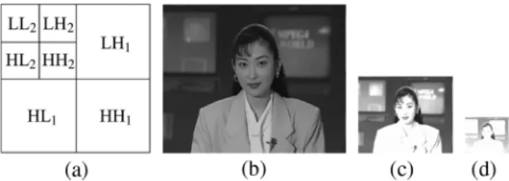
Fig. 2. Examples of 2D-DWT downsampling. (a) Frequency bands after two-level DWT decomposition. (b) Original Akiyo image. (c) Reduction of Akiyo image 50% in both width and height. (d) Reduction of Akiyo image 25% in both width and height.
Fig. 3. The relationship between the 2D-DWT and the downsampled images.
to yield more detail of the analysis signal at the lower frequency band. Such analysis is referred to as multiresolution. Haar’s and Antonini 9/7 Wavelet Transform is used to increase the speed of execution of the wavelet transform [44]. The 2D-DWT is ap-plied as a one-dimensional DWT in the horizontal direction and then another in the vertical direction.
Fig. 2(a) plots the corresponding locations of the images of the frequency bands decomposed by 2D-DWT. Fig. 2(c) and Fig. 2(d) shows the subsampled results obtained using the Akiyo image, displayed in Fig. 2(b), after two levels of DWT pro-cessing. Fig. 2(c) and Fig. 2(d) truncate the values that are above 255 and below 0 for demonstration, but the value are retained in the evaluation progress. As shown in Fig. 3, for the th frame, and are the LL band of the first and the second order decomposition, respectively.
There are some problems existing in this downsampling method. Firstly, the computational complexity is heavy because it requires more additions and more multiplications for sub-samping one pixel. Secondly, in the normal hardware design, 8 bits are required to store the gray level value of the pixel from 0 to 255. However, the range of the downsamping pixel by 2D-DWT goes beyond 0 to 255, and more bits are necessary. Therefore, the memory bandwidth of the hardware architecture and the chip area will be increased. Although the range of the pixels can be normalized into 0 to 255 to reduce the bandwidth, the extra hardware for normalization is essential. The compu-tational complexity and the die size will be also increased.
Averaging Filter: This method is the same as the bilinear
in-terpolation that rescale the image with 50% in both width and height. Therefore, the quality of the reduced image can be en-sured. For the th input frame, , the upper level images are computed by executing the following downsampling:
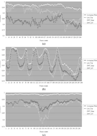
Fig. 4. The correlations between the adjacent images for averaging filter, left_top method, Haar DWT, and Antonini 9/7 DWT in: (a) Flower garden; (b) Stefan; and (c) Mobile.
where represents the value at position of the th frame at level .
The hardware implementation for the averaging filter is simple, and only three additions and one bit shift operations are required for subsampling one pixel.
Comparison: The main purpose of the motion estimation
is to eliminate the temporal redundancies existing in adjacent frames. Therefore, the quality will be increased when higher correlation exists between the successive images. The correla-tion is defined as
(4)
where and are the means of and ,
respectively.
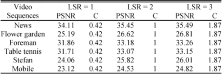
Fig. 4 shows that the correlations between the downsampled images. It is observed that the correlations of the Haar DWT and the averaging filter are almost the same, and are much greater than the left-top and the Antonini 9/7 DWT methods, especially in the video sequences that their backgrounds are more com-plex. In Table I, the estimation results are depicted, and it shows that the average PSNR of Haar DWT and the averaging filter
TABLE I
THECOMPARISON OF THEVIDEOQUALITYBETWEENVARIOUS
DOWNSAMPLINGMETHODS FORLEFT-TOP, HAAR’SDWT, ATONINI’S9/7 DWT,AND THEAVERAGINGFILTER INdB
are similar. Moreover, the image quality of the left-top method is bad, and Antonini 9/7 DWT even gets worse quality than it in some cases. The results indicate that downsampling method plays a very important role in MMEA. The estimation perfor-mance of adopting averaging filter significantly exceeds that of the method that considers only the left-top pixel, and can be used to design an efficient downsampling hardware architecture.
The fact that the performance of the Antonini 9/7 DWT is worse than that of the Haar DWT is unexpected. Theoretically speaking, the Antonini 9/7 DWT can reserve more informa-tion in low frequency band since it adopts higher order filters. However, the statement stands only when the inverse transform, which is not executed in the downsampling procedures, is per-formed. Therefore, Antonini 9/7 DWT requires higher compu-tational power, but it provides poor quality in the downsampling stage of HMEA. Moreover, if the scaling factor of Haar DWT is replaced by 1/2, the results are exactly the same as the aver-aging filter, and can get rid of the dynamic range problem. The reason of the averaging filter outperforms the Haar DWT is that is chosen as its scaling factor, and this will cause the inac-curacy of the values of downsampled pixels. Considering both the coding performance and the hardware design, the averaging filter is chosen to downsample the image in HMEA.
B. Framework of HMEA
The overall searching process can be separated into three levels. As presented in Fig. 1, when level 2 receives an input image , the image will be downsampled to and , where the resolutions of and are one-quarter and one-sixteenth of that of , respectively. Let the entire search range at level 2, or , be . After the original image has been downsampled, the search pro-cedure, illustrated in Fig. 5, begins. Let Cur , Pre , and MV denote the current MB, the previous frame search area, the th search area and the th MV candidate at level l, re-spectively. The detailed process at each level will be described below.
Search at Level 0: Two MV candidates, MV and MV , are manipulated at this level. MV is defined as the least MV that obtained by a full search within a given search area, i.e.,
MV SAD (5)
and MV is the second least MV, i.e. MV MV over the
Fig. 5. The hierarchical search procedure. TABLE II
THEPSNR PERFORMANCE AND THECOMPLEXITY, C, ANALYSIS INDIFFERENT
NUMBER OF THEMV CANDIDATES AT THECOARSESTLEVEL
According to Fig. 5, Cur is a 4 4 block, and Pre is a 12 12 previous frame search area. In level 0, the search range is only one-quarter that at level 2, and the number of operations is much lower. The experimental results presented in Table II clearly reveal that if three least minimum MV candidates are selected, the performance only increases slightly. Hence, only 2 MV candidates are chosen. Accordingly, the computational complexity can be reduced, and the performance maintained.
Search at Level 1: Local searches are performed around these
two MV candidates from level 0. The local search range (LSR) is also an important issue for HMEA, and it is smaller than that at level 0 to reduce the number of operations. If LSR is too small, the estimation results may be incorrect when the move-ment of the MB is big. On the other hand, if LSR is too large, the computational complexity will be increased greatly. Further-more, the hardware design must be considerate. If LSR in the different levels are not the same, two hardware blocks are re-quired, and the chip area will be increased. Thus, LSRs are the
TABLE III
THEPSNR PERFORMANCE AND THECOMPLEXITY, C, ANALYSIS INDIFFERENT
LSRS IN THEMIDDLE AND THEFINESTLEVEL
same in level 1 and level 2 of HMEA. Table III shows that the re-lationship between the LSR and the estimation performance. Al-though the PSNR increases when LSR extends, the complexity is also raised. The improvement of the PSNR for LSR from 2 to 3 is not as great as it from 1 to 2. Based on these test results, LSR equal to 2 is chosen.
In Fig. 5, Cur is an 8 8 block, and Pre is a 12 12 pre-vious frame search area. Cur performs two full local searches, whose LSR equals 2, over two search areas , , to refine the search results from level 0, and , denote the corresponding MV candidate from level 0. Following the local searches, an MV candidate MV can be determined
MV SAD (6)
where , and
.
Search at Level 2: MV is found by a local search around the MV candidates from level 1
MV SAD (7)
where
MV
As illustrated in Fig. 5, Cur is a 16 16 block, and Pre is a 20 20 previous frame search area. The MV searching process is completed when MV , defined in (8), has been determined
MV MV MV MV (8)
Half-Pel Search: After MV is manipulated, the half-pel search is started. Therefore, the neighboring half accuracy pixels of the MV have to be calculated, and a total of 833 pixels and eight SADs are necessary. The complexity of the half-pel search is defined as (9), and it is combined with the pixels and the SAD operations
(9) where , , and are the number of operations required to compute a half accuracy pixel, the SAD operation, and the frame rate, respectively. Fortunately, the downsampling stage of HMEA has already calculated 144 pixels for half-pel search
so the complexity of half-pel search for HMEA, , can be reduced as (10)
(10)
Complexity Analysis: The overall search procedure includes
the downsamping stage , the integer-pel search, and the half-pel search, and is defined as (11). The half accuracy pixels only need one addition to manipulate where the preprocessed pixels for HMEA requires three of them, and the shift operation can be reduced by reading the higher bits of the pixel. Therefore, the cycles for downsampling a pixel are three times to them for the half accuracy pixels. During the overall search procedure, the search complexity is described as (12)
(11)
(12) where represents the search complexity in level . In the case of FSBMA, computational complexity is given by (13)
(13) The SAD operation for a pixel, which is described in (1), needs 256 additions, and 256 subtractions, and the manipulation for a half accuracy pixel only requires one addition. Therefore, the relationship between and can be illustrated as (14)
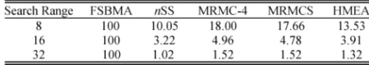
(14) Equations (9) to (13) demonstrate that the computational complexity of HMEA will be only 3.9% and 1.3% of that of it of FSBMA for of 16 and 32, respectively.
C. Experimental Results
The MPEG test video sequences News, Foreman, Flower garden, Table tennis, Stefan, and Mobile are used to evaluate the performance of HMEA.
All the sequences consist of 300 frames; the frame rate is 30 frames/s, and the image size is CIF. The search range is defined
as where . The mean square error (MSE),
and PSNR is used for the measurement of performance. MSE is defined as (15)
MSE (15)
where is the th motion compensated image, respectively. PSNR is an engineering term for the ratio between the maximum possible power of a signal and the power of corrupting noise that affects the fidelity of its representation. PSNR is defined as (16)
PSNR MAX MSE (16)
TABLE IV
THECOMPARISON OF THECOMPLEXITY, INCLUDINGHALF-PELSEARCH, BETWEENFSBMA,NSS, MRMC-4, MRMCSANDHMEAINDIFFERENT
SEARCHRANGES
TABLE V
THEPSNR COMPARISONS OFVARIOUSFAST-SEARCHALGORITHMS INdB
where MAX is the maximum pixel value of the image. Since the pixel in the evaluation is from 0 to 255, the PSNR can be modified as (17)
PSNR MSE (17)
The performance of HMEA is compared to that of two well-known algorithms: FSBMA and n-step search (nSS) [45], and two MMEA algorithms, MRMC-m [39] and MRMCS [42]. nSS is a general version of the 3SS to cover the increased search
ranges ( for respectively). MRMC-m
is a MMEA based on multiple candidates, and it has m-candi-dates at each resolution. MRMCS uses three MV candim-candi-dates at level 1, and two of the MV candidates that are obtained on the basis of minimum matching error at level 0, and the other one is based on the spatial MV correlation. MRMC-m and MRMCS are both using left-top method for downsampling the images, and they also keep multiple winners at the top level. All al-gorithms are implemented by the standard C language to esti-mate the PSNR performance, and the input sequences are all the same, which can avoid the distinct quality due to the different fragment in the same test patterns. Since the software model cannot represent the hardware architecture, the estimation speed and the memory usage will be discussed in Section IV.
Tables IV and V present the results. Table IV describes the complexity of these four algorithms in the various search area, and Table V shows the performance in terms of PSNR. In order to truly reflect the MV accuracy, the estimation results are made by the MB and the corresponding MV without the in-flation of the error residuals. According to these tables, HMEA provides a prospective PSNR performance that is close to that of FSBMA, and a greater search range corresponds to a lower complexity. Although the averaging filter has higher compu-tational complexity than the left-top method which MRMCS and MRMC-m adopted, the number of the MV candidates in level 1 of HMEA is less than these two MMEAs. Moreover, HMEA has not only lower SAD operations in the integer pixel search, but also a smaller number of pixel interpolations for the half-pel one. The reduced arithmetic can compensate the extra manipulations of the averaging filter. Therefore, the overall
Fig. 6. The hierarchical search procedure.
complexity of HMEA is smaller than MRMCS and MRMC-m. In Table IV, nSS exhibits the lowest computational complexity with consistency that is proper for hardware implementation. However, it can be observed that nSS provides the lower PSNR especially for the sequences that have fast motion. Besides, although MRMC-m also needs a consistent computational complexity, it contributes the worse PSNR than MRMCS and HMEA for similar computational complexity. Meanwhile, the PSNR of HMEA is slightly less than MRMCS in the video sequences that contain high motions since MRMCS applies an MV candidate based on spatial correlation in an MV field. However, MRMCS needs many more cycles to manipulate the MV candidates. Based on the computational complexity resultes determined by the tests, HMEA is the most suitable algorithm for VLSI implementation.
HMEA can reduce more SAD operations when the image resolution is larger from (12) and (13), and in SD and HD resolution, the reduced complexity is 3.4 and 9.1 times of that in CIF. Furthermore, the use of averaging filter improves the estimation accuracy of HMEA. This can be examined in Table V by comparing the performance between MRMC-m and HMEA. By changing the downsampling method, HMEA can reduce the number of the MV candidates at level 1 and even obtain the better PSNR than MRMC-m. For video sequences having large motion, the effect becomes more noticeable. As a result, in HMEA, only one local search is performed at level 2, and two MV candidates are enough for maintaining the good quality. Therefore, the overall computational cost and data bandwidth burden of HMEA decrease.
III. PROPOSEDVLSI ARCHITECTURE
HMEA, described in Section II, is mainly for low bit-rate video coding in MPEG-4. Therefore, a search range of [ 16.0, 15.5] is adopted. In this VLSI architecture, a 2-D difference accumulation unit (DAU) is proposed for the VLSI architecture. Based on this 2-D architecture, the image data can be input to the DAUs in pipeline, and the encoding speed can be greatly in-creased while maintaining a negligible degradation in the coding performance.
A. Overall Architecture
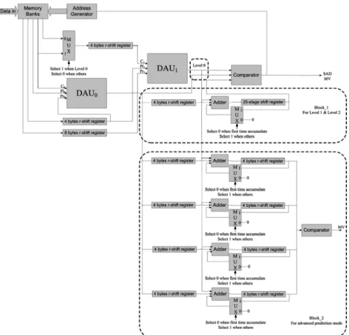
As stated in Section II, HMEA comprises three levels, and the computation proceeds at each level with different MB sizes and search ranges. A basic computational component performs a 4 4 block FSBMA within the search range of [ 2, 2] at all levels. Therefore, a DAU that executes a 2 FSBMA for a 4 4 subblock is introduced. Each DAU is divided into five-stage pipelines, each of which has five PEs, to compute the SADs. Two DAUs are adopted to complete the process. Accordingly, the efficiency of data reuse can be markedly improved, and the encoding speed can be increased. Fig. 6 shows the overall archi-tecture. HMEA consists of two DAUs, an address generator, two comparators, 14 registers, and memory banks. As stated above, the block size and the search range are different at each level, and one DAU can compute an SAD of a 4 4 block. There-fore, when the computational proceeds to level 1 and level 2, SAD should be accumulated twice and eight times, respectively. Block 1 in Fig. 6 is the accumulator for level 1 and level 2. The advanced prediction mode should compare SADs of four 8 8
Fig. 7. The hierarchical search procedure.
subblocks in a 16 16 MB, to predict an MV, and Block 2 is employed in this mode (8 8 prediction mode). The memory banks and the address generator provide a scheduled data flow to DAUs to calculate SAD . The registers are used to delay the data input to fit the timing designed in Fig. 7, which is the timing diagram of level 0. The search window of the previous frame is divided into two parts, which are input to different DAUs. Thus, the image data can be reused more effectively, and selecting an MV takes only 56 cycles.
B. Downsampling
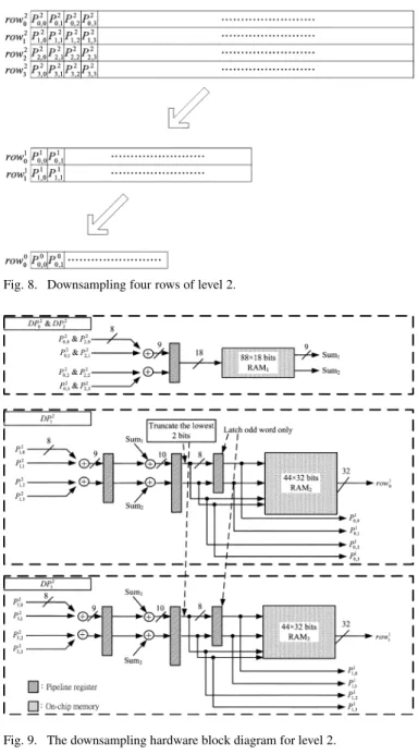
Downsampling is the preprocessing part of this motion esti-mation architecture. A simple way to downsample an image is to input all of the image data to RAM, and then average four pixels as a single pixel. After numerous manipulations, an image that has one-quarter of the original resolution is generated. This ap-proach requires a large part of the available memory to store the original image, and this large amount of memory substantially increases the die size. A pipelined hardware is derived to down-sample the images to fit the limitations on the memory and the die size. Fig. 8 shows an example of downsampling four rows of level 2, where is the th pixel of the th row, row , at level l, and Figs. 9 and 10 illustrate the pipelined downsampling hard-ware for levels 2 and 1, respectively. DP , RAM , and Sum are the data path of row , the on-chip memory of each DP, and
Fig. 8. Downsampling four rows of level 2.
Fig. 9. The downsampling hardware block diagram for level 2.
Fig. 10. The downsampling hardware block diagram for level 1.
the temporal summation registers. In Fig. 8, four rows of level 2 are subsampled to get two rows of level 1 and one row of level
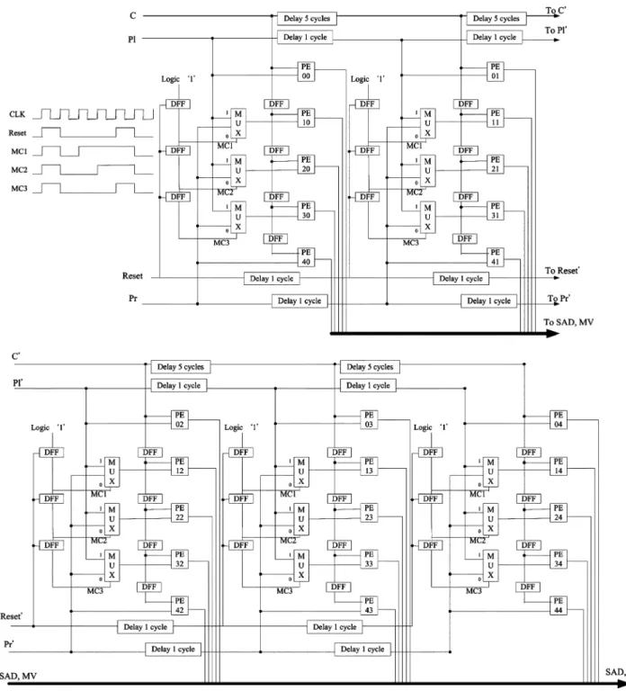
Fig. 11. The architecture of a 2-D DAU.
0 each loop, and a total of 72 loops are required for one CIF image. The procedure is described step by step as follows.
1) As shown in Fig. 9, row is input to DP . After row has been processed, the results of and
are stored in RAM .
2) row is input to DP , and the result of row is stored in RAM . At the same time, the data output by the second stage of the pipeline register in DP , , , , and , are input to DP , and the results of and
are stored in RAM .
3) row is input to DP , and the results of and are stored in RAM .
4) row is input to DP . As in step 2, the result of row is stored in RAM , and , , , and are input to DP . Then, the result of row will be stored in RAM . 5) Finally, RAM , RAM , and RAM contain the results of
levels 1 and 0, respectively.
6) Repeat steps 1 to 5 a total of 71 times to complete the downsampling procedure of a CIF image.
A row of CIF images has 352 pixels, and four bytes are input per cycle. Thus, 88 cycles are required to fetch a row of level 2, and 22 cycles to get a row of level 1. The pixels are down-sampled in pipeline, so the addition operation and the data input are generally performed simultaneously to significantly increase
the overall speed. Nevertheless, 22 extra cycles are required for storing one row of level 0 into RAM5. In this architecture, four rows of level 2 and two rows of level 1 are input and one row of level 0 is stored in one turn. Hence,
cycles are needed for a CIF image. Therefore, 76 cycles are required for an MB.
C. DAU
HMEA works after the downsmapling process. The number of PEs in DAU is decided by the operating frequency, the reso-lution of the images, and the search area. More PEs will increase the estimation speed but enlarge the chip area. Since the basic search range is 2, five PEs will be a stage, and five-stage 2-D semisystolic architecture is adopted as a DAU which is shown in Fig. 11. The basic search unit (BSU) is a one-dimensional systolic PE array [42]. The reuse of data is not good enough, so the current block and previous block data must be loaded again in each loop. The architecture requires 40 mega clock cycles to complete the motion estimation of 30 CIF images. If other system overhead, such as bus arbitration or software overhead, must be considered, real-time encoding will be difficult. Ac-cordingly, an enhanced 2-D semisystolic DAU architecture with improved data reuse capability uses two DAUs to improve the processing speed. HMEA reduces the bandwidth requirement by 80% and only 5.88 mega clock cycles are required to accom-plish the motion estimation of 30 CIF images.
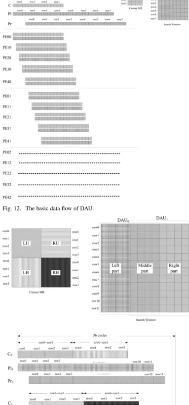
Fig. 11 depicts the architecture of DAU, for a 4 4 current block FSBMA whose search range equals 2, and it consists of 25 PEs, flip flops (DFFs), multiplexers (MUXs), and simple logic for flow control of the input data. The basic data flow is shown in Fig. 12. The current MB is a 4 4 block and the search window is a 12 12 block; the search window is partitioned into two parts, Pl and Pr. The data are input to DAU from C, Pl, and Pr ports, as illustrated in Fig. 11. Starting from cycle 0, C and Pl are sequentially read through each port, and after four cycles, the data is input into Pr. The current MB and the search window are input into five-stage pipeline PEs with the corresponding timing, and 25 SADs in a search range of 2 can be calculated. The PE00 and PE10 will accumulate the SADs associated with the search positions ( 2, 2) and ( 1, 2), respectively. Sim-ilarly, the other PEs will compute the SADs of the other search positions. The main advantage of DAU is that the current MB and the search area only have to input once. Therefore, only 36 clock cycles are required to generate 25 SADs, where BSU in [42] needs 80 cycles.
D. DAU Processing at Each Level
Based on DAU architecture and the basic data flow, a mo-tion estimamo-tion architecture, shown in Fig. 6, where Ci, Pli, and Pri are the input ports of DAUi ( , 1), is developed. Two DAUs are employed to accelerate the motion estimation and improve the reusability of data. This architecture is commonly used among different levels and can extend the search range without adding additional hardware. The data flow at level 0, 1, and 2 are shown in Figs. 7, 13, and 14, respectively. The de-tails of the processing at each level are as follows.
1) Level 0: The current MB is a 4 4 block and the search window is a 12 12 block. The search window is
parti-Fig. 12. The basic data flow of DAU.
Fig. 13. The timing diagram of HMEA for level 1.
tioned into two parts; one part is input to DAU and the other is for DAU . Fig. 7 shows the data partition and the data flow. C is fed twice by the current MB and C re-ceives the same data four cycles thereafter. The left part, the middle part, and the right part of the search window
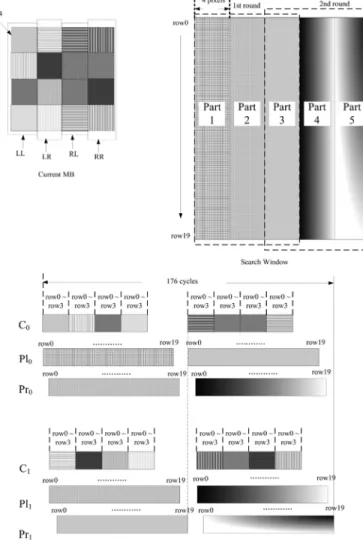
Fig. 14. The timing diagram of HMEA for level 2.
which is illustrated in Fig. 7 are put into Pl , Pr , Pl , and Pr with the corresponding timing, respectively. After 17 cycles, the 1st SAD will be generated with the relative MV from DAU and the other SADs and the MVs will also be available continuously from DAU and DAU . The output of SADs from DAU and DAU are input to the com-parator. The minimum SAD and its corresponding MV are retained in the comparator until the search of level 0 is com-pleted. After 56 cycles, two MV candidates are obtained. 2) Level 1: The two MV candidates which are found in level
0 are used as the starting point of level 1. Then, FSBMA with a search range of 2 is used to refine MV. At level 1, the current MB is an 8 8 block and the search window is a 12 12 block. The current block is partitioned into four parts: left-upper, left-bottom, right-upper and right-bottom (LU, LB, RU, RB), and the search window is partitioned into three parts, as shown in Fig. 13. C is fed by LU and LB of the current MB, and C receives RU and RB four cy-cles later. In the search window, the condition is the same as that of the search at level 0. The left part, the middle part, and the right part of the search window, depicted in Fig. 13, are put into Pl , Pr , Pl , and Pr with the corresponding timing, respectively. After 17 cycles, the 25 SADs of LU and RU parts begin to be output from DAU and DAU se-quentially, and these SADs are sent to block 1 in Fig. 6, to
accumulate with the SADs of LB and RB later. Following 56 cycles, the first SAD of level 1 with the relative MV are output from 25-stage shift register in Fig. 6, and the remaining 24 SADs with the MVs are also output sequen-tially. SADs of level 1 are sent into the comparator and the minimum SAD with the corresponding MV is retained in the comparator. After cycles, the first search of level 1 is finished. Level 0 has two MV candidates, so the search of level 1 must be performed twice, once for each of these two MV candidates, to determine which MV is the proper one. Therefore, searching for level 1 takes a total of 162 cycles per MB.
3) Level 2: The most suitable MV obtained in level 1 is the start point of the local search in level 2. FSBMA whose search range equals 2 is performed to refine MV found in level 1. At level 2, the current MB is a 16 16 block and the search window is a 20 20 block. The current block is partitioned into 4 portions (LL, LR, RL, and RR) and the search window is sparated into five fragments, part 1 to 5, as shown in Fig. 14. The overall search procedure contains two rounds.
3.1) The first round: LL is input to C , and LR is fetched by C four cycles later. Part 1, part 2, and part 3 are put into Pl , Pr , Pl , and Pr with the corresponding timing. At the 17th cycle, the first SAD with the relative MV is input to 25-stage shift register, as shown in Fig. 6, to be accumulated later with the other SADs of the remaining parts. Following 88 cycles, these 25 SADs of LL and LR are stored in the 25-stage shift register.
3.2) The second round: The second round is begun at the 89th cycle; RL begins to be input into the C , and RR is fetched by C four cycles later. In the search window, part 3, part 4, and part 5 are put into Pl , Pr , Pl , and Pr with the corresponding timing. The 25 SADs are input to block 1 in Fig. 6 and accu-mulated with the 25 SADs, which were determined in the first round. At the 152th cycle, the first SAD of level 0 with the related MV is output from the 25-word circular buffer and input to the comparator. The minimum SAD and its corresponding MV are retained in the comparator. At the 176th cycle, the first MV is output from the 25 word circular buffer, and the search process in level 2 requires a total of
cycles.
E. Half-Pel Search
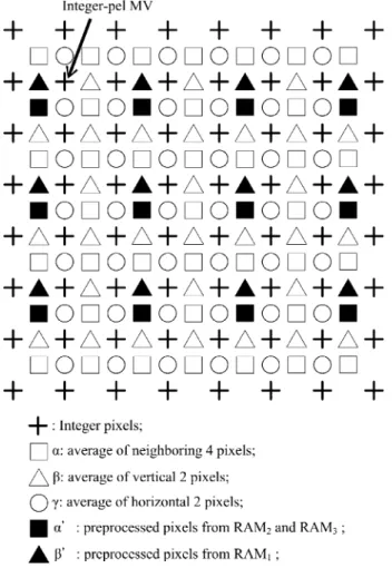
After the final integer-pel MV is computed in Section III-D, a half-pel search is to be performed around it. The search procedure is similar to it in level 2, and the current block is also partitioned into 4 partitions for DAUs processing. The main advantage of HMEA in half-pel search is that the aver-aging hardware and the on-chip memory for the half accuracy pixels are already existed. Moreover, some of the pixels are preprocessed during the downsampling stage described in Sec-tion III-B. Since the downsampling images and are no longer necessary, the on-chip memory can be reused to store the interpolated image. As shown in Fig. 15, denotes
Fig. 15. Interpolation for half-pel search.
the four-pixel average, and and represent the vertical and the horizontal two-pixel average, respectively. and are the pixels which can be directly read from RAM1 to RAM5, which is shown in Figs. 9 and 10, respectively, and other pixels can be generated from the downsampling hardware directly. First, with 17 16 pixels are manipulated and be stored into the memory for the search area. Since 17 4 pixels of are already existed in the downsampling stage, the number of the computations can be reduced. Then, the search steps which is analogous to them in the level 2 are started, and downsampling hardware begins to generate with 17 17 pixels by the value of in pipeline. When is sent to estimate the MV, the values of can be calculated. A total of 8 SADs of the interpolated image are computed, and 404 cycles are needed in a half-pel search.
IV. IMPLEMENTATIONRESULTS
The hardware architecture, as described in Section III, is successfully implemented. Additionally, the estimation per-formance is the same as the software model addressed in Section II-C. If the ME module constantly accesses the external memory of the video coding system, then the system bus will become too busy. Accordingly, the on-chip SRAM is applied to store the current block data and the search area data. Data are reused in the overlapped search area between horizontally adjacent MBs to reduce the loading cycles. With the high video
quality and the fast speed, HMEA requires 1393-byte on-chip single port SRAM which are used to store the downsampled images, the current MB, and the search area for estimation. Al-though the size of the current MB and the search area vary with level, the maximum values at level 2 are adopted. The number of cycles required computing an MV is the sum of the opera-tions in downsampling stage and different levels, as described
in Section III, which is cycles,
so an operating frequency of only 5.88 MHz is sufficient for real-time application for CIF images. As for the half-pel search, no more on-chip memory and logics are added, and a total of cycles are required for manipulating an MV. The averaging filter, which is applied by HMEA, can increase the quality and speed, and it is suitable for half-pel search. In MMEA, the design of the hardware and the number of mem-ories needed for downsampling are not mentioned in [42] and [43]. The VLSI circuits for HMEA were described in VHDL and synthesized by SYNOPSYS Design Analyzer using UMC 0.18 um CMOS standard cell library. In Table VI, HMEA is com-pared with three kinds of the hardwareMMEA, FSBMA, and PMVFAST. Most ME architectures will not work alone, and they will be integrated into the video encoders. Consequently, the cycles for calculating an MV of a block and the required op-erating frequency for the real-time application for CIF images are estimated. The operating frequency of 30 MHz, which is quite enough for the video encoders with HMEA to compress the sequences in CIF format at real-time, is assumed. The com-parison is illustrated in Table VI. It demonstrates that HMEA is the fastest architecture in MMEA, and has a reasonable chip area. The number of PEs dominates the size, so HMEA is a little larger size with ten times and three times as many PEs as in [42] and [43] respectively. In [43], the cycles and the area outperform that of HMEA, but it uses much more memory than HMEA. The memory will occupy a large die size and greatly increases the cost. Moreover, it can only support integer-pel search. In [42], the on-chip memory is lower than HMEA, so the reuse of data is inefficient. Hence, the required operating frequency for the real-time application for CIF images is too high. Mean-while, the comparison of HMEA with FSBMA and PMVFAST indicates that the area-speed performance of HMEA is better. In Table VI, three architectures, HMEA, [42], and [8], support half-pel search, and HMEA is the fastest among them. Due to the design of the averaging filter, the equivalent gate counts and the on-chip memory can remain the same in the integer-pel search. With the low bandwidth requirement of the system bus, the fixed processing cycles, and the high video quality, HMEA can be easily integrated in video coding systems.
V. CONCLUSION
This paper has addressed the design and implementation of HMEA, which efficiently uses an averaging filter for downsampling and multiple MV candidates for fast search. HMEA exhibits its advantages by providing not only a PSNR performance close to that of FSBMA, but also a simple hard-ware architecture that is appropriate for VLSI implementation. The developed VLSI architecture includes an averaging filter to downsample the images and 2-D semisystolic PE arrays
TABLE VI
THECOMPARISONBETWEENHMEA WITHOTHERARCHITECTURES FORMMEA, FSBMA,ANDPMVFAST. THESEARCHRANGEAMONGEACHFRAMEWORK
ISDIFFERENT,THEEQUIVALENTGATECOUNTSINCLUDESCONTROL ANDADDRESSGENERATIONOVERHEADS ASWELL AS THECOMPUTATIONALCORE
(PES),AND THEMB SIZE IS162 16
to compute the SAD in pipeline. It is implemented with rea-sonable area, 59K with 1393 bytes of on-chip RAM, and a low required operating frequency, 5.88 MHz for the search area of [ 16, 15], and 10.68 MHz for [ 16.0, 15.5], in the real-time application for CIF images. Furthermore, the area-speed performance of HMEA is better than many existing architectures based on FSBMA or MMEA.
ACKNOWLEDGMENT
The authors would like to thank Prof. Y.-L. Chen, Prof. C.-C. Chiu, and the anonymous reviewers for their valuable suggestions toward the improvement of this paper.
REFERENCES
[1] L. De Vos and M. Stegherr, “Parameterizable VLSI architectures for the full-search block-matching algorithm,” IEEE Trans. Circuits Syst., vol. 36, no. 10, pp. 1309–1316, Oct. 1989.
[2] T. Komarek and P. Pirsh, “Array architecture for block matching al-gorithms,” IEEE Trans. Circuits Syst., vol. 36, no. 10, pp. 1301–1308, Oct. 1989.
[3] K. M. Yang, M. T. Sun, and L. Wu, “A family of VLSI designs for the motion compensation block matching algorithm,” IEEE Trans. Circuits
Syst., vol. 36, no. 10, pp. 1317–1325, Oct. 1989.
[4] C. H. Hsieh and T. P. Lin, “VLSI architecture for block-matching mo-tion estimamo-tion algorithm,” IEEE Trans. Circuits Syst. Video Technol., vol. 2, no. 2, pp. 169–175, June 1992.
[5] Y. K. Lai and L. G. Chen, “A data-interlacing architecture with two-di-mensional data-reuse for full-search block matching algorithm,” IEEE
Trans. Circuits Syst. Video Technol., vol. 8, no. 2, pp. 124–127, Apr.
1998.
[6] H. Yeo and Y.-H. Hu, “A novel modular systolic array architecture for full-search block matching motion estimation,” IEEE Trans. Circuits
Syst. Video Technol., vol. 5, pp. 407–416, Oct. 1995.
[7] Y. H. Yeh and C. Y. Lee, “Cost-effective VLSI architectures and buffer size optimization for full-search block -matching algorithms,” IEEE
Trans. Very Large Scale Integr. (VLSI) Syst., vol. 7, no. 3, pp. 345–358,
Sep. 1999.
[8] J.-F. Shen, T.-C. Wang, and L. G. Chen, “A novel low-power full-search block-matching motion estimation design for H.263+,” IEEE
Trans. Circuits Syst. Video Technol., vol. 11, no. 7, July 2001.
[9] J. C. Tuan, T. S. Chang, and C. W. Jen, “On the data reuse and memory bandwidth analysis for full-search block-matching VLSI architecture,”
IEEE Trans. Circuits Syst. Video Technol., vol. 12, no. 1, pp. 61–72,
Jan. 2002.
[10] L. C. Liu, J. C. Chien, Y. H. Chuang, and C. C. Li, “A frame-level FSBM motion estimation architecture with large search range,” in
Proc. IEEE Conf. Advanced Video Signal Based Surveillance, 2003,
pp. 327–333.
[11] W. F. He, Y. L. Bi, and Z. G. Mao, “Efficient frame-level pipelined array architecture for full-search block matching motion estimation,” in Proc. IEEE Int. Symp. Circuits Syst., 2005, pp. 2887–2890. [12] W. F. He, M. L. Zhao, C. Y. Tsui, and Z. G. Mao, “A scalable
frame-level pipelined architecture for FSBM motion estimation,” in Proc.
IEEE Int. Conf. VLSI Design, 2007, pp. 830–835.
[13] W. Li and E. Salari, “Successive elimination algorithm for motion es-timation,” IEEE Trans. Image Process., vol. 4, no. 1, pp. 231–236, Jan. 1995.
[14] X. Q. Gao, C. J. Duanmu, and C. R. Zou, “A multilevel successive elimination algorithm for block matching motion estimation,” IEEE
Trans. Image Process., vol. 9, no. 3, pp. 501–504, Mar. 2000.
[15] M. Brunig and W. Niehsen, “Fast full-search block matching,” IEEE
Trans. Circuits Syst. Video Technol., vol. 11, no. 2, pp. 241–247, Feb.
2001.
[16] Digital Video Coding Group, ITU-T Recommendation H.263 Software Implementation Telenor R&D, 1995.
[17] Y. S. Chen, Y. P. Huang, and C. S. Fuh, “Fast block matching algorithm based on the winner-update strategy,” IEEE Trans. Image Process., vol. 10, no. 8, pp. 1212–1222, Aug. 2001.
[18] S. Zhu and K.-K. Ma, “A new diamond search algorithm for fast block-matching motion estimation,” IEEE Trans. Image Process., vol. 9, no. 2, pp. 287–290, Feb. 2000.
[19] Y.-W. Huang, S.-Y. Chien, B.-Y. Hsieh, and L. G. Chen, “An efficient and low power architecture design for motion estimation using global elimination algorithm,” in Proc. IEEE Int. Conf. Acoust., Speech,
Signal Process., May 2002, vol. 3.
[20] Y.-W. Huang, S.-Y. Chien, B.-Y. Hsieh, and L.-G. Chen, “Global elimination algorithm and architecture design for fast block matching,”
IEEE Trans. Circuits Syst. Video Technol., vol. 14, no. 6, pp. 898–907,
[21] P. I. Hosur and K. K. Ma, “Motion vector field adaptive fast motion estimation,” in Proc. 2nd Int. Conf. Information, Communications and
Signal Processing, Singapore, Dec. 1999.
[22] A. M. Tourapis, O. C. Au, and M. L. Liou, “Predictive Motion Vector Field Adaptive earch Technique (PMVFAST)Enhancing block based motion estimation,” presented at the Vis. Commun. Image Process. Conf., San Jose, CA, Jan. 2001.
[23] A. M. Tourapis, “Enhanced predictive zonal search for single and mul-tiple frame motion estimation,” presented at the Vis. Commun. Image Process. Conf., San Jose, CA, Jan. 2002.
[24] T. Li, S. Li, and C. Shen, “A novel configurable motion estimation ar-chitecture for high-efficiency MPEG-4/H.264 encoding,” in Proc. Asia
South Pac. Des. Automat. Conf., Jan. 2005, vol. 2, pp. 1264–1267.
[25] T. Koga, K. Iinuma, A. Hirano, Y. Iijima, and T. Ishiguro, “Mo-tion-compensated interframe coding for video conferencing,” in Proc.
Nat. Telecommun. Conf., New Orleans, LA, Nov./Dec. 1981, pp.
C9.6.1–C9.6.5.
[26] R. Li, B. Zeng, and M. L. Liou, “A new three-step search algorithm for block motion estimation,” IEEE Trans. Circuits Syst. Video Technol., vol. 4, no. 4, pp. 438–422, Aug. 1994.
[27] L. M. Po and W. C. Ma, “A novel four-step search algorithm for fast block motion estimation,” IEEE Trans. Circuits Syst. Video Technol., vol. 6, no. 3, pp. 313–317, Jun. 1996.
[28] M. Bierling, “Diaplacement estimation by hierarchical block matching,” in Proc. Int. Symp. Vis. Commun. Image Process., 1988, vol. SPIE-1001, pp. 942–951.
[29] G. Gupta and C. Chakrabarti, “Architectures for hierarchical and other block matching algorithm,” IEEE Trans. Circuits Syst. Video Technol., vol. 5, no. 6, pp. 477–489, Dec. 1995.
[30] T. Onoye et al., “A VLSI architecture for MPEG2 MP@HL real time motion estimator,” in Proc. IEEE Int. Symp. Circuits Syst., 1996, pp. 664–667.
[31] M. Uz, M. Vetterli, and D. Le Gall, “Interpolative multiresolution coding of advanced TV and compatible subchannels,” IEEE Trans.
Circuits Syst. Video Technol., vol. 1, pp. 86–99, Mar. 1991.
[32] J. Chalidabhongse and C.-C. J. Kuo, “Fast motion vector estimation using multiresolution-spatio-temporal correlations,” IEEE Trans.
Cir-cuits Syst. Video Technol., vol. 7, no. 3, pp. 477–488, Jun. 1997.
[33] S. Zafar, Y.-Q. Zhang, and B. Jabbari, “Multiscale video representa-tion using multiresolurepresenta-tion morepresenta-tion compensasion and wavelet decom-position,” IEEE J. Select. Areas Commun., vol. 11, no. 1, pp. 24–35, Jan. 1993.
[34] J. Li, X. Lin, and Y. Wu, “Multiresolution tree architecture with its application in video sequence coding: A new result,” in Proc. Int. Symp.
Vis. Commun. Image Process., 1993, vol. 2094, pp. 730–741.
[35] K. M. Nam, J. S. Kim, R. H. Park, and Y. S. Shim, “A fast hierarchical motion vector estimation algorithm using mean pyramid,” IEEE Trans.
Circuits Syst. Video Technol., vol. 5, no. 4, pp. 344–351, Aug. 1995.
[36] K. W. Chun and J. B. Ra, “An improved block matching algorithm based on successive refinements of motion vector candidates,” Signal
Process. Image Commun., vol. 6, pp. 115–122, 1993.
[37] K. W. Cheng and S. C. Chan, “Fast block matching algorithms for motion estimation,” in Proc. IEEE Int. Conf. Acoust., Speech, Signal
Process., 1996, pp. 2311–2314.
[38] J. C.-H. Ju, Y.-K. Chen, and S. Y. Kung, “A fast rate-optimized mo-tion estimamo-tion algorithm for low-bit-rate video coding,” IEEE Trans.
Circuit Syst. Video Technol., vol. 9, no. 7, pp. 994–1002, Oct. 1999.
[39] X. Song, T. Chiang, X. Lee, and Y.-Q. Zhang, “New fast binary pyramid motion estimation for MPEG2 and HDTV encoding,” IEEE
Trans. Circuits Syst. Video Technol., vol. 10, pp. 1015–1028, Oct.
2000.
[40] B.-M. Wang, J.-C. Yen, and S. Chang, “Zero waiting-cycle hierarchical block matching algorithm and its array architecture,” IEEE Trans.
Cir-cuits Syst. Video Technol., vol. 4, no. 1, pp. 18–28, Feb. 1994.
[41] L. De Vos, “VLSI architectures for the hierarchical block-matching al-gorithms for HDTV applications,” in Proc. Int. Symp. Vis. Commun.
Image Process., 1990, pp. 398–409.
[42] J. H. Lee, K. W. Lim, B. C. Song, and J. B. Ra, “A fast multi-resolution block matching algorithm and its LSI architecture for low bit-rate video coding,” IEEE Trans. Circuits Syst. Video Technol., vol. 11, no. 12, pp. 1289–1301, Dec. 2001.
[43] K.-B. Lee, H.-U. Chin, H.-C. Hsu, and C.-W. Jen, “QME: An efficient subsampling-based block matching algorithm for motion estimation,” in Proc. Int. Symp. Compound Semicond., May 2004, vol. 2, pp. 23–26.
[44] B. E. Usevitch, “A tutorial on modern lossy wavelet image compres-sion: Foundations of JPEG2000,” IEEE Signal Process. Mag., vol. 18, no. 5, pp. 22–35, Sep. 2001.
[45] J. Lu and M. L. Liou, “A simple efficient search algorithm for block matching motion estimation,” IEEE Trans. Circuits Syst. Video
Technol., vol. 7, no. 2, pp. 429–433, Apr. 1997.
Bing-Fei Wu (S’89–M’92–SM’02) was born in
Taipei, Taiwan, R.O.C., in 1959. He received the B.S. and M.S. degrees in control engineering from National Chiao Tung University (NCTU), Hsinchu, Taiwan, in 1981 and 1983, respectively, and the Ph.D. degree in electrical engineering from the University of Southern California, Los Angeles, in 1992.
Since 1992, he has been with the Department of Electrical Engineering and Control Engineering, where he is currently a Professor. He has been involved in the study of intelligent transportation systems for many years and leads a research team to develop the first Taiwan smart car, TAIWAN iTS-1, with autonomous driving and active safety system. His current research interests include vision-based vehicle driving safety, intelligent vehicle control, multimedia signal analysis, embedded systems and chip design.
Prof. Wu founded and served as the Chair of the IEEE Systems, Man and Cy-bernetics Society Taipei Chapter in Taiwan, in 2003. He has been the Director of the Research Group of Control Technology of Consumer Electronics in the Au-tomatic Control Section of National Science Council (NSC), Taiwan, from 1999 to 2000. As an active industry consultant, he is also involved in the chip design and applications of the flash memory controller and 3C consumer electronics in multimedia systems. The research has been honored by the Ministry of Ed-ucation as the Best Industry-Academics Cooperation Research Award in 2003. He received the Xerox-Fujitsu Academic Research Award in 2007; the Distin-guished Engineering Professor Award from Chinese Institute of Engineers in 2002; the Outstanding Information Technology Elite Award from Taiwan Gov-ernment in 2003; the First Prize Award of TI China-Taiwan DSP Design Contest in 2006; the Outstanding Research Award in 2004 from NCTU; the Golden Acer Dragon Thesis Award sponsored by the Acer Foundation in 1998 and 2003, respectively; the First Prize Award of the We Win (Win by Entrepreneurship and Work with Innovation & Networking) Competition hosted by the Industrial Bank of Taiwan in 2003; and the Silver Award of Technology Innovation Com-petition sponsored by the Advantech Foundation in 2003.
Hsin-Yuan Peng (S’03) was born in Taitung, Taiwan,
R.O.C., in 1980. He received the B.S. degree in elec-trical and control engineering from National Chiao Tung University, Hsinchu, Taiwan, in 2002. He is cur-rently working toward the Ph.D. degree at the same institute.
His research interests include video processing, and embedded system design.
Mr. Peng received the First Prize Award of TI China-Taiwan DSP Design Contest in 2006, and the Silver Award of Technology Innovation Competition sponsored by the Advantech Foundation in 2003.
Tung-Lung Yu was born in Chang-Hua, Taiwan,
R.O.C., in 1980. He received the B.S. and M.S. degrees from the Department of Electrical and Con-trol Engineering, National Chiao Tung University, Hsinchu, Taiwan, in 2003 and 2005, respectively.
Since January 2006, he has been a full-time Dig-ital ASIC Engineer with Faraday Technology Corpo-ration, Hsinchu, Taiwan, where he is involved in the design of integrated circuit of video codec. His re-search interests include video coding algorithm and VLSI architecture for image/video processing.