Robust Controller Design for a Synchronous Reluctance Drive
Ming-Tsan Lin and Tian-Hua Liu
Department of Electrical Engineering National Taiwan University of Science and Technology
Taipei, Taiwan 106 R. 0. C . Abstract--- This paper presents a systematic robust controller design for a synchronous reluctance drive system. Based on a simplified model of the system, a robust position controller has been derived. A digital signal processor, TMS-320-C3OY is used to implement the control algorithm. Furthermore, all the current, velocity, and position control loops are executed by the digital signal processor. The system, as a result, is very flexible. Although the hardware circuit of the system is very simple, the synchronous reluctance drive system can accurately control a one-axis table. In addition, the system also has good transient response, load disturbance response, and tracking ability. Several experimental results validate the theoretical analysis.
I. INTRODUCTION
The synchronous reluctance motor (SRM) has been recognized to have many advantages. For example, its structure is rugged and simple. In addition, its rotor does not have any winding or magnetic material. The SRM, therefore, is easy to manufacture. Prior to ten years ago, the SRM was regarded as inferior to other types of ac machines due to its lower average torque and larger torque pulsation. Recently, however, researchers have proposed many methods to improve the characteristics of the motor as well as the drive system [1]-[2]. The SRM has been shown to be suitable for ac drive systems for several reasons. First, it is not necessary to compute the slip of the SRM as it is with the induction motor. As a result, there is no parameter sensitivity problem. Next, it does not require any permanent magnetic material as the permanent magnet synchronous motor does. Many researchers have applied vector control to the SRMs. These studies, however, used only proportional-integral (PI) controllers. To obtain a high performance drive system, the
The National Science Council of R. 0. C. supported this work under grant NSC87-2213-E-011-054.
controller design is very important; however, there are only a few papers, which have studied this topic. For example, Liu, et al. proposed a h z z y sliding-mode controller design for a SRM drive [3]. With this system, however, it is necessary to estimate the acceleration of the motor. Moreover, only a speed-loop controller is designed to achieve both a fast transient response and a good load disturbance response. The fizzy sliding-mode control algorithm, therefore, is very complicated and is difficult to implement. In this paper, an advanced
H"
controller to improve the transient response and load -disturbance response of the system has been proposed. The design procedures of the control algorithm are complicated; however, the implementation of the control law is very simple. In addition, the closed-loop SRM drive system performs well by using this proposed control method. A one-axis precision table is driven by the proposed SRM drive system. The whole system performs well. For example, it has a fast response and a good load disturbance rejection capability. The steady-state position error is +1 bit. In addition, the position control system has good tracking ability. It can track a time varying command well. To the best of the authors' knowledge, this is a new control algorithm to drive the SRM. Moreover, this is the first time the SRM drive system has been applied in an industrial position control. The SRM was not applied in industrial position control due to its high torque pulsation. This paper first uses an SRM drive to control an industrial one-axis precision position control. The experimental results show that an SRM drive can be successfully applied in industrial position control with satisfactory performance.11. MATHEMATICAL MODEL
A. System Description
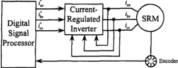
The block diagram of the SRM drive system is shown in Fig. 1. The system includes four major parts: the motor, the
inverter, the sensors, and the digital signal processor.
-
'a,-
Current- Processor EncoderFig. 1 Block Diagram of Drive System B. Motor and Load Dynamics
The mathematical model of an
S R M
without damping winding can be described, in the synchronousd e - q e
reference !?ame, by the following nonlinear differential equations:pi,=(v,
-rs id + w ,
L, iq,)lL,
piqs=(vqs-r, iqs 0,
L, i*)lLqs
(2)(1)
where p is the differential operator dldt, i, and are the d e
-
q
e axis stator currents,vd
andvqs
are thed e
-
qe
axis stator voltages,r,
is the stator resistance,w,
is the electrical speed of the rotor shaft, andL,
and Lq, are thede-q'
axis stator inductances. The electro- magnetic torque of the motor isi,
T
=- C ( L ,-
L ~ ,
)idi,
e 2 2
where
Po
is the number of poles of the motor. The speedof the motor is
1
J
P O , =
-(c
- q
- B O , ) (4)P e r = wr ( 5 )
where
J
is the inertia constant of the motor and load, is the external load torque, B is the viscous frictional coefficient of the motor and load, and8,
is the shaft position of the motor. The main purpose of this paper is to develop a high performance controller for an SRM drive. As a result, this paper focuses on the position-loop controller design. In order to reduce the required computing time of the DSP, a simple three-phase independent current- regulated control method is used here. The current control is executed by the DSP with a 50 ps sampling interval. The switching frequency of the inverter, therefore, is 20kHz.
Then, the three phase currents
i,
, ib, , i,
can follow the three-phase current commands i,, Zb,,i,.
After the coordinate transformation &om the a-b-c stationery fiame toa
.*
*the
d e
- q e
synchronous frame, we can conclude that thed e
- q e
axis currentsid,
and i, follow thed e
-
q e
axis current commandsiJs
andvery
well. The torque command (idea torque), therefore, can be expressed aswhere
T,*
is the torque command,i;
is the d-axis current command,K;
is the torque constant, andiis
is the q-axis current command.111. CONTROL ALGORITHM
Fig. 2 shows the block diagram of the SRM control system. The H state-feedback controller is design as following steps. First, letting x l = W r andxz =
er,
we can obtain the dynamic equations:I I I I I I I I *ZI I I
Fig. 2 The block diagram of control system
-9
1
0
0
d
0
0
0
0
0
0
- 1
- a ,
1
0
0
0
0
-
'T+
(7)0
0
0
0
0
a
b S0
0
l-4
1
0
B,
=lo
1
0
0
0
b,
0
0
a
0
a ( b T
0
D,,
=-=[;I,
L - 1c,
=[o
- 1
0
01,
o*l
=[1
01,
where A I , B 1 , B2, C1, C,, Dl,,and DZ1 are relative matrices or vectors of the dynamic equations. The xI to x4 are state variables, ZI to Z, are the weighted states, r is the reference input, d is the external disturbance, U is the control input,
and a,, b,, aT , bT, d,, and
a
are the parameters of the weighted functions. Then, we can define the performance index as [4]m
<
=j(z'z
- p
2wTw )it (10)0
where
5
is the performance index, andp
is a constantwhich is assigned by the designer. Then, after some mathematical processes, we can derive
U' =
-[(D;D1,)-'D;C,
+(D;D,,)-IB,TP
1
x= - k _
x
(1 1)where U * is the optimal control input, and
k,
is theHm
feedback gain. The matrix P is obtained by solving the following Riccati equation,Iv.
EXPERIMENTAL RESULTSA. Implementation
The block diagram of the implemented drive system is shown in Fig. 1. The system consists of four major parts: a DSP system, an inverter, an
SRM,
and some sensors. A TMS-320-C30 DSP system is used here. The DSP system executes the control algorithm, the d-q axis to a-b-c axis coordinate transformation, and the current regulated PWM switching algorithm. Finally, the DSP determines the firing signals and send them to the inverter. A closed-loop system is thus achieved. The three-phase current deviations of the motor are small because the DSP can finish executing thecurrent-regulated algorithm in only Sops. In addition, the DSP finishes executing the position-loop control in 1 ms. Because most of the jobs are implemented by software, the hardware circuit, therefore, is 'very simple. The inverter is realized by using six insulated gate bipolar transistors (IGBTs). The motor is a 3-phase, 4 pole, 220V, 0.75 HP SRM, with 1800 r/min rated speed, manufactured by the Reliance Electric Company. The parameters of the motor are shown in Table I. The IGBTs have the following specifications: 50A continuous rating current, 1 OOA maximum peak current, and 1200V rating voltage. The sensor of the system includes two parts: the Hall-effect current sensors and the encoder. The Hall-effect sensors are type LP-lOOP, made by LEM Company. The bandwidth of the Hall-effect sensors is about 100
kHz.
The DSP reads the output signals of the Hall-effect sensors via analog-to-digital (AD) converters. The AD converters are 12 bit, with 3 ps conversion time. The encoder originally outputs 2000 position pulses with one index pulse for every mechanicalrevolution. However, it can output 8000 pulses with an index pulse by using a multiplier circuit.
TABLE I
Parameters of the Motor
7s 2 0
L*
0. I38H0.0572H
LP
J 0.002394 N . d s
(with one-axis moving table)
0.00512 N . d s
J L
(with one-axis table and external inertia)
B. Experimental Results
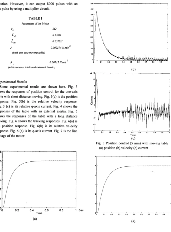
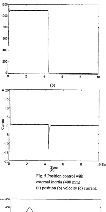
Some experimental results are shown here. Fig. 3 shows the responses of position control for the one-axis table with short distance moving. Fig. 3(a) is the position response. Fig. 3(b) is the relative velocity response. Fig. 3 (c) is its relative q-axis current. Fig. 4 shows the responses of the table with an external inertia. Fig. 5 shows the responses of the table with a long distance moving. Fig. 6 shows the tracking responses. Fig. 6(a) is the position response. Fig. 6(b) is its relative velocity response. Fig. 6 (c) is its q-axis current. Fig. 7 is the line voltage of the motor.
m
m
6
'
1
.- .- a-
g35;-
I
1
2 1 1 -I
1
0.2 0.4 0.6 0.8 1 Sec Time 5 - 4 - c 0 .--
.- g3 a - 2 - 1 - 0.2 0.4 0.6 0.8 1 Sec Time 4 I*I
o:i o:2 013 014 0:s 0:s o:7 0:s 019!
SecTime
Fig. 3 Position control (5 mm) with moving table (c)
1200 r 1000 800 600 400. 2 -
i
0 - 2 - - 4 - . I U I I , I 1 Time 4o 0.1 oz 0.1 0.4 0.5 0.6 0.7 0.8 0.0 ( s e c (c)Fig. 4 Position control (5 mm) with moving table and external inertia (a) position (b) velocity (c) current. 0 2 4 6 8 10, 0 2 4 6 8 10.
-7
1
J 2 4 6 8 10 Sec -20;&y
Fig. 5 Position control with external inertia (400 mm)
(a) position (b) velocity (c) current.
0 2 4 6 8 10 Sec
0 2 4 6 8 10 Sec Time A 20 15 10 5
i o
3 -5 -1 0 -15 2 4 6 a 10 Sec -20 Time ( c)Fig. 6 The position tracking responses (a) position (b) velocity (c) current.
200
-
100-
a, 0 - -100-
-200-
-3001
J 0 20 40 60 80 100 ms -400’
TimeFig. The PWM voltage of the SRM.
V. Conclusions
This paper proposes the
H a
controller design for a hlly digital synchronous reluctance drive. The experimental results show that the whole drive system has good transient response, load disturbance response, and tracking ability. This paper proposes a new direction to design and implement a new position control algorithm for the synchronous reluctance drive.References
[
11
L. Xu, X. Xu, T. A. Lipo, and D. W. Novotny, “Vector control of a synchronous reluctance motor including saturation and iron loss,”IEEE Trans. Ind. Appl., vol. 27, no. 5, pp. 977-985, Sep./Oct. 1991.
[2]
R. Lagerquist, I. Boldea, and T. J. E. Miller, “Sensorless control ofthe synchronous reluctance motor,” IEEE Trans. Ind. Appl., vol. 30,
no. 3, pp. 673-682, May/June 1994.