Modeling and Emulation of a Furnace in IC
Fab Based on Colored-Timed Petri Net
Sheng-Ya Lin and Han-Pang Huang,
Member, IEEEAbstract—In integrated circuit (IC) manufacturing, the wafer processing takes more time in furnaces than other equipment. How to effectively integrate furnaces with other automated ma-chines is very important. In particular, using the real furnace for testing not only introduces trouble but also wastes time. This paper aims to model and construct an emulation environment for the furnace. The colored timed Petri net (CTPN) is used to model the furnace. Based on CTPN, the dynamic behaviors of the furnace, such as loading, processing, unloading and wafer count mismatching, can be emulated. The proposed CTPN model is hierarchical and modular. The hierarchical architecture is built by dividing the behaviors of the furnace to make the model more compact and the modular modeling makes the model flexible and easy to use. On the other hand, the furnace emulator provides a quasi environment for testing so that potential problems of the system can be detected in advance and the testing time can be economized.
Index Terms—Furnace, IC fab, modeling, Petri net.
I. INTRODUCTION
I
N AN integrated circuit (IC) factory, a furnace consists of crucible, susceptor (crucible support) and rotation mecha-nism, heating element and power supply, and chamber [14]. The primary process steps of the furnaces in semiconductor industry include oxidation, impurity diffusion, low pressure-chemical vapor deposition (LP-CVD), and so on. The folky furnace equipment can be either horizontal type or vertical type. Since horizontal tubes occupy more space than vertical ones, the latter has become the mainstream.The process of impurity thermal diffusion consists of three steps: loading wafers into furnace, performing thermal dif-fusion, and unloading wafers from the furnace. To prevent the distortion of the wafers, the speed control of loading and unloading within a range is necessary. As a rule, both of them take about 10–20 min.
In general, a batch of wafers is marked by a lot ID initially. Such a lot ID records the handling procedures of wafers from the head to the tail in the factory. When the wafers are in the furnace area, the computer depends on the lot ID to load and execute the corresponding recipe. First, the wafers are counted and the wafer cassette is loaded into the shelf of the furnace by the transfer machine. If the wafers are mismatched, the furnace
Manuscript received January 15, 1998; revised April 20, 1998. This work was supported in part by the National Science Council of Taiwan under Grant NSC86-2622-E-002-025R.
The authors are with the Robotics Laboratory, Department of Mechanical Engineering, National Taiwan University, Taipei, Taiwan 10674, R.O.C. (e-mail: hphuang@w3.me.ntu.edu.tw).
Publisher Item Identifier S 0894-6507(98)05882-5.
Fig. 1. Icon definition of CTPN.
shows an alarm message on the screen. The wafer count can be set either by the operator or the batch ID. Which method is adopted depends on the level of automation. Then the wafers are charged into the T-boat by the robot. Finally, the T-boat is boated in the process chamber, reactive gas is fed into the furnace under a sealed circumstance, and the temperature is warmed. After the process is complete, the temperature of the furnace is reduced. Then the T-boat is boated out and waits until the temperature of the wafers is cooled down. The robot takes the wafers to the cassette on the shelf and the transfer machine carries the cassette back to the I/O ports. This completes the wafer handling in the furnace area.
Along with production wafers, monitor wafers and dummy wafers are added into the T-boat, a quartz boat, for control-ling quality, getting processing data, and heating uniformly. According to the feature of the furnace process, the dummy wafers are always put at the top and bottom of the tube, and the monitor wafers are inserted in the proper place 0894–6507/98$10.00 1998 IEEE
LIN AND HUANG: MODELING AND EMULATION OF FURNACE IN IC FAB 411
Fig. 2. Architecture of the furnace model.
between production wafers. T-boat is the real location for the calefaction of the wafers. Usually, a tube contains about three monitor wafers, 12 dummy wafers, and 144 production wafers.
The furnace equipment takes about 20% of total cost in a semiconductor plant. In the process of system integration, it is bothersome and would delay the regular production flow for using the true machine for testing. Using the real furnace for testing not only introduces trouble but also wastes time. It is desired to develop a system model and construct an emulation environment for the furnace so that the testing and system integration can be efficient and flexible. The furnace model can be used to analyze the dynamic behavior of the furnace equipment. In particular, the model can be referred to as a single tube emulator, and it is easy to modify and to extend in the future. The design of the furnace emulator could economize the testing time, reduce frequency of borrowing machines, and reveal design flaws at early stages. There are two merits in such a simulation environment.
1) Find problems in advance: Some flaws may exist in the development stage of the upper level system. Those flaws can be found by the emulated environment. 2) Economize testing time: The average processing time
of a normal batch treatment in the furnace is 6 h. By normalizing the time of the emulator, the action can be accomplished just in several minutes.
However, the modeling and emulation of the furnace are seldom addressed in the literature [10], [12], [18]. Especially, the Petri net-based models of the furnace have not been developed to our knowledge. Hence, this paper intends to develop the model and emulation environment for the furnace. The model construction and emulator design will be based on the proposed colored timed Petri net (CTPN) analysis. In the subsequent context, the proposed CTPN will be first discussed and followed by the CTPN model of the furnace. Section IV is the implementation of the furnace emulator. Finally, the conclusion is drawn.
II. COLORED TIMED PETRINET(CTPN)
The CTPN extends the framework of the original PN by adding color, time and modular attributes to the net. The color attribute [1]–[9], [11], [13], [15]–[17], [21] is developed to tackle large systems that have many similar or redundant log-ical structures. The time attribute [1]–[3], [5]–[7], [11], [15], [16], [22] allows various time-based performance measures to be added in the system model. A time-delay can be assigned to transitions to model the time properties in a system.
In a PN, when a token in a place is available, the condition of the output transition determines the fate of the token. If the output transition is an immediate transition, then the transition is enabled to fire and the token is released from the input place to the output place(s). On the other hand, if the output transition is a timed transition, then the token will not be released until a prescribed time delay is reached. Notice that the number of arcs between the input place(s) and the output transition(s) is also important. The directed arc connects between a place and a transition, or vice versa.
Since modular design is essential for a compact furnace model, individual modules are developed first for each process of the furnace. Then, the modules of different processes are integrated together to form the complete furnace model. In this approach, macro transitions are often used to realize a modular design [2], [3], [5]–[8], [15]–[17], [21], [22]. A macro transition is the combination of a series of transitions, places and arcs. A macro transition may consist of several sub-macro transitions (it is, in essence, a sub-macro transition but in different levels). A system can be composed of many macro transitions. The interconnection between different levels is achieved by communication places. Based on macro transitions and communication places, a hierarchical and modular model of the furnace can be constructed.
The communication and interface between the macro transi-tions are through four types of communication places, and they are pitch-up, pitch-down, catch-up, and catch-down places. The pitch-down and catch-down places are applied to the
Fig. 3. The first level CTPN model of furnace.
higher level modules, and the pitch-up and catch-up places are for the lower level modules. The higher level modules use the pitch-down place to send (or pitch) tokens to the lower level modules, and use the catch-down place to receive (or catch) tokens from the lower level modules. Similarly, the lower level modules use the pitch-up place to send tokens to the higher level modules, and use the catch-up place to catch tokens from the higher level modules [5]–[7], [15].
A hierarchical CTPN is a seven-tuple, CTPN
( ), where
set of (immediate) places; set of timed transitions; set of immediate transitions;
set of communication places; set of macro transitions; set of directed arcs;
color set of transition and place.
These elements are further elaborated as follows.
1) Place: is a finite set of places, , including immediate places and communication places. Notice that the ordinary places can describe the conditions or properties of resources; the communication places can describe the communication packages in a hierarchical CTPN.
2) Transition: is a finite set of
transitions, , including immediate transitions, timed transitions, and macro transitions. Notice that the immediate transitions can describe the behaviors or events (without time factor) of resources; the timed transitions can describe the time properties of resources. 3) Color: and represent the color sets of places
in and transitions in ;
where and are nonnegative integers; and are colors of places and transitions, and denotes the cardinality.
4) Input and output functions:
, is an input function. It describes the mapping relation from the transition with color to the place with color , where is an nonnegative integer. Similarly,
is an output function.
5) Marking: to , has elements.
is an ( ) vector defined as
where is the number of tokens of colors at this instant; is the total number of colors in place . denotes the number of tokens of colors in place .
is the initial marking.
6) Conditions of enabling and firing: The transition is enabled with respect to the color if
After the transition is fired, two outcomes could appear. For an immediate transition the new marking
LIN AND HUANG: MODELING AND EMULATION OF FURNACE IN IC FAB 413
Fig. 4. Loading CTPN model, refer to Fig. 3 for the notation.
For a timed transition, the temporary marking is
After the delay in , the marking becomes
7) Time function: It is simply the time attribute in transi-tions. For the transition , is the time required by the timed transition associated with the color to complete the firing.
III. CTPN MODEL OF FURNACES
The action of the furnace is divided into three main parts and four subparts. Fig. 2 shows the architecture of the model.
The color set of the furnace is defined as follows.
• Wafer Set: The major kinds of wafers in the semi-conductor factory are production, dummy and monitor wafers. Production wafers are normal wafers for cus-tomers. Dummy wafers are used for avoiding the un-evenness of the temperature. Monitor wafers are indexes whether the batch qualities are good. Therefore, Wafer Set consists of Token , Token , and Token . • Command Set: Commands of an upper level machine
sent to the furnace are primarily divided into loading, processing and unloading. Thus, Token load, Token proc, and Token unld constitute the Command Set.
• Resource Set: A furnace has 2 I/O ports, 1 transfer ma-chine, 1 robot, and 1 process chamber. Hence, Resource Set consists of Token , Token , Token , and Token .
• Shelf Set: A shelf is a transient place for mounting wafers. Thus, Shelf Set consists of Token , Token , and Token
.
• ErrCmd Set: When wafers are mismatched, three methods can be applied, i.e., “abort,” “count again,” and “take in.” ErrCmd Set consists of Token , Token , and Token
.
The major parts of the furnace CTPN model are loading, processing and unloading. The first level of a hierarchical and modularized CTPN model is shown in Fig. 3. For the sake of self-explanation in the CTPN model, some symbols are added to the graph. For instance, the condition state is denoted by the arc—r pc ; the release of resource or the use of the process chamber is denoted by the arc—if then ; the condition “if the token with the color of wafer then pass” is denoted by the arc—(w) ; the symbol i/o tm rob pc represents the initial resource. These symbols will not appear on the simulator.
A. Loading in Furnace Equipment
Fig. 4 shows the loading CTPN model. First, the host sends S2F65 message to the furnace for loading request and there are no wafers on the shelf of the furnace. Therefore, one batch of dummy wafers, one batch of monitor wafers, and four batches of wafers can be put on the shelf. The initial state of the place PS has 1 , 1 , and 4 color tokens. For the same reason, the place PR has two I/O ports, one transfer machine, one robot, and one process chamber at initial state. Hence, it has 2 , 1 , 1 , and 1 color tokens. The commands the host can send are primarily divided into load, process, and unload. Thus, place PHC has 1 , 1 , and 1 color tokens. Note that the reader can refer to [10] for detailed description of places and transitions.
The furnace receives a series of commands and executes its corresponding actions. The I/O ports and the transfer machine must be available before the wafers enter the shelf. Then the furnace counts the number of wafers. If the wafer count mismatches the setting value, the furnace executes the error
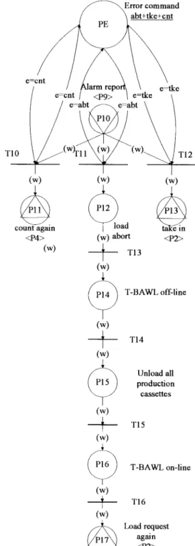
Fig. 5. Mismatching CTPN model, refer to Fig. 3 for the notation. treatment. A wafer mismatching CTPN is modeled to treat such a condition and will be discussed in next. Through the pitch-down communication place P9, tokens go to the mismatching CTPN from the loading CTPN. Another error treatment is the breakdown of the transfer machine. This condition needs the engineer to repair. Then the furnace will work after repair.
When all wafers are in the shelf, the furnace completes the loading action, and the wafers wait for processing, which is discussed in Section III-C.
LIN AND HUANG: MODELING AND EMULATION OF FURNACE IN IC FAB 415
Fig. 6. Processing CTPN model; refer to Fig. 3 for the notation.
B. Mismatching in Furnace
When the mismatch of wafer count occurs, tokens go to the mismatching CTPN through the loading CTPN by pitch-down communication place P9 and are received in catch-up communication place P10. There are three commands, count again, take in and abort, for the operator to choose. For different choice, tokens go to different places in the mismatching CTPN, as shown in Fig. 5. If “count again” command is executed, tokens go to the corresponding
catch-down communication place P4 in the loading CTPN through the pitch-up communication place P11 in the mismatching CTPN. If the commands of “take in” is chosen, tokens go to catch-down communication place P2 in the loading CTPN through pitch-up communication place P13 in the mismatching CTPN. If “abort” command is chosen, tokens go on the middle way. At the end, tokens return to the catch-down communication place P2 in the loading CTPN through the pitch-up communication place P10 in the mismatching CTPN.
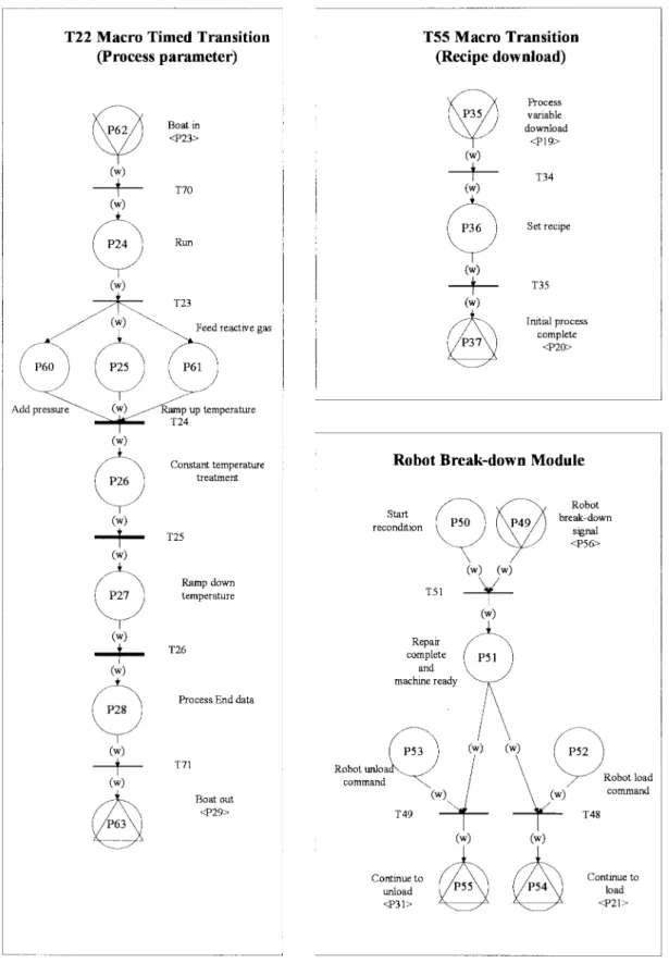
Fig. 7. Macro timed and breakdown CTPN models; refer to Fig. 3 for the notation.
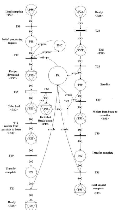
C. Processing in Furnace
Fig. 6 shows the processing CTPN module. When the wafers are loaded completely, tokens go into the T55 macro transition by pitch-down communication place P19. The macro transition T55 is a sub-CTPN module to handle recipes. Upon
having wafers in the shelf, the robot takes five pieces of wafers each time from the shelf to the chamber if the robot and process chamber are available. When all wafers are sent into the process chamber, according to the recipe, the process will start. T19 is a timed transition because it needs time to move
LIN AND HUANG: MODELING AND EMULATION OF FURNACE IN IC FAB 417
Fig. 8. Unloading CTPN model, refer to Fig. 3 for the notation.
wafers from the shelf to the processing chamber. If the robot is out of order, tokens go to the robot breakdown module through the pitch-down communication place P56 to catch-up communication place P49. After the operator repairs the robot, the wafers continue to be moved until all of them are in the process chamber.
When all wafers are in the process chamber, the temperature of the furnace will rise. The timed macro transition T22 is in charge of such things. After the timed macro transition T22 has been executed, tokens return to the upper level colored timed Petri net. Now, the wafers are moved from the process chamber to the shelf and the processing of wafers is complete.
T22, T55 and the robot breakdown CTPN models are shown in Fig. 7.
D. Unloading in Furnace
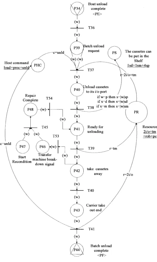
The unloading of the furnace acts like the reverse of the loading. The furnace receives the unloading command and the transfer machine starts to unload wafers two batches at a time. The error treatment of the transfer machine is also included in the unloading colored timed Petri net module, as shown in Fig. 8. When two batches of wafers have been unloaded, two slots in the shelf become available. In the model two colored tokens are released to the Shelf Set. The unloading procedure will continue until one monitor batch, one dummy batch, and four production batches are completely unloaded.
IV. IMPLEMENTATION OF A FURNACE EMULATOR In general, it is necessary to understand the dynamic behav-ior of the emulated machine in order to construct the emulator. The features of the dynamic behavior of the furnace can be classified into two parts.
1) The journey of normal treatment including loading, processing and unloading: these procedures occupy 80% of time for furnace processing.
2) The difference between the furnace and the general machine: the furnace equipment treats not only produc-tion wafers but also dummy and monitor wafers for manufacturing.
The CTPN model is used as a referential warranty. Spe-cially, the adhocery and judgment of the emulated program can be easily expressed in the model. In addition, the emulated program can be easily modified based on the CTPN model. In order to relax the restriction in communication and to provide a flexible emulation environment, the emulator is built in a client-server architecture and both SECSII and HSMS commu-nication protocols are facilitated. The commucommu-nication between the furnace and the remote host is through SECS-II protocol. The realization of the whole emulated program is based on the CTPN model. The emulator is developed by using Visual C 4.2 and FASTech’s Windows compatible semiconductor Equipment Communications Standard (WinSECS) messaging software [20].
The WinSECS control supports RS-232 and HSMS equip-ment connection [19] to facilitate communication with generic equipment model (GEM) compliant manufacturing equipment. WinSECS OCX includes five primary classes: Csecs, CsecsLi-brary, CsecsTransaction, CsecsMessage, and CsecsItem. The relationship among these classes can be found in [10], [20]. The WinSECS OLE Control should be inserted into the VC program before using it. Since OCX’s are DLL’s, a 32-bit OCX cannot be used in the 16-bit container.
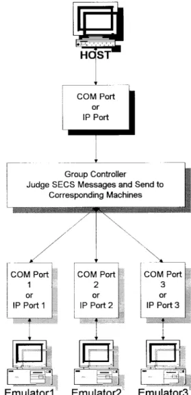
Each emulator communicates with the upper level machine by RS232 port or the IP port of network, as shown in Fig. 9. The developed emulator possesses several features:
1) establish the SECS message communication;
2) operation journey of batch wafers includes the loading, processing and unloading;
3) treat the abnormality of the furnace; and 4) verify all SECS messages.
Fig. 9. The emulator communicates with the upper level through commu-nication port.
In the emulated program, the meaning of places, transitions, the enabled transition, and generation and consumption of the colored tokens are briefly described as follows.
1) Place: Represent the status of the remote host or furnace equipment.
2) Transition: Represent the remote host or furnace equip-ment sending SECS messages to each other.
3) The enabled condition of the transition: Represent the description of flow control in the emulated program. 4) The generation and the consumption of colored tokens:
Set the relevant variables and flags of the emulated program.
The emulator consists of two child Windows:
1) scroll view displays the animation of the CTPN; 2) message list view shows SECS-II messages to or from
the emulator.
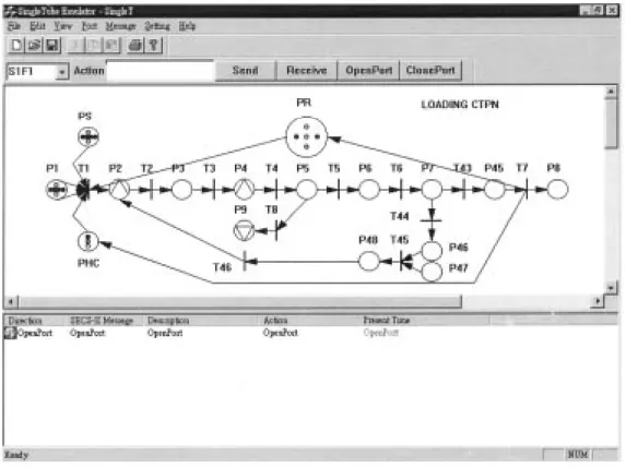
The furnace emulator consists of loading module, mis-matching module, processing module, unloading module and breakdown module. For simplicity, only the loading CTPN module, shown in Fig. 10, is given here. The furnace emulator also emulates the situation when errors occur. If the error
LIN AND HUANG: MODELING AND EMULATION OF FURNACE IN IC FAB 419
Fig. 10. The loading CTPN diagram of the emulator.
Fig. 11. The status that mismatch occurs.
occurs, the furnace emulator displays the message box on the screen and waits for the handling from the operator. The CTPN diagram changes according to token distribution. For example, Fig. 11 shows the status that mismatch occurs. In this case, there are three methods to treat errors. The default method is
to abort loading. If the other method is selected, tokens will go to the corresponding path. Note that S6F12, S6F11, etc. in Fig. 11 are SECS II message. The reader can refer to [10] and [19] for details. The breakdown of the transfer machine and the robot may occur during loading or unloading. It is
treated in a similar way. After the machine is repaired, the corresponding CTPN will be changed accordingly.
V. CONCLUSIONS
The CTPN model and the emulator for the furnace in an IC fab have been constructed in this paper. In particular, the CTPN model has been integrated into the design of the emulator. The model can be referred to as a single tube emulator, and it is easy to modify and extend in the future. The design of the furnace emulator not only emulates the activities occurred in the furnace but also economizes the testing time of the furnace for system integration. In order to relax the restriction in communication and to provide a flexible emulation environment, the emulator is built in a client-server architecture with SECS II and HSMS communication protocols. It has been justified that the proposed model and emulator are compatible to the real furnace in the IC fab. The performance analysis of the CTPN models used in the emulator will be the future work.
ACKNOWLEDGMENT
The authors are grateful to the reviewers for their valu-able comments and to Taiwan Semiconductor Manufacturing Company for data support and verification.
REFERENCES
[1] A. A. Desrochers and R. Y. AI-Jaar, Applications of Petri Net in
Manufacturing Systems—Modeling, Control, and Performance Analysis.
New York: IEEE Press, 1995.
[2] H. P. Huang and P. C. Chang, “Specification, modeling and control of a flexible manufacturing cell,” Int. J. Prod. Res., vol. 30, no. 11, pp. 2515–2543, 1992.
[3] H. P. Huang and Y. H. Tseng, “Modeling and graphic simulator for integrated manufacturing systems,” Intell. Autom. Soft Comput., vol. 1, pp. 183–186, 1994.
[4] K. Jensen, “Colored Petri nets and the invariant method,” in
Theoreti-cal Computer Science. Amsterdam, The Netherlands: North Holland, 1981, vol. 14, pp. 317–336.
[5] C. H. Kuo, “Application of reliability and equipment manufacturing to flexible manufacturing systems,” M.S. thesis, Dept. Mech. Eng., National Taiwan Univ., Taipei, 1995.
[6] C. H. Kuo, H. P. Huang, K. C. Wei, and S. Tang, “Dispatching and simulation for highly model-mixed automotive plants,” in Proc. Int.
Conf. Automation Technology, Taiwan, 1996, vol. 1, pp. 423–430.
[7] C. H. Kuo and H. P. Huang, “Colored timed Petri net based statistical process control and fault diagnosis to flexible manufacturing systems,” in IEEE Int. Conf. Robotics and Automation, Albuquerque, NM, Apr. 1997, pp. 2741–2746.
[8] M. Kamath and N. Viswanadham, “Applications of Petri net based model in the modeling and analysis of flexible manufacturing systems,” in Proc. IEEE Int. Conf. Robotics and Automation, 1986, pp. 312–317. [9] J. I. Lee, “Fuzzy colored timed Petri net model in network flow control
and distributed FMC emulator design,” M.S. thesis, Dept. Mech. Eng., National Taiwan Univ., Taipei, 1996.
[10] S. Y. Lin, “Monitor of furnace workcell,” Master thesis, Department of Mechanical Engineering, National Taiwan Univ., taipei, 1997.
[11] S. S. Lu and H. P. Huang, “Modularization and properties of flexible manufacturing systems,” in Advances in Factories of the Future, CIM
and Robotics, M. Cotsaftis and F. Vernadat, Eds. Amsterdam, The Netherlands: Elsevier, 1993, pp. 289–298.
[12] W. L. Mao, “Design and implementation of an active furnace monitoring system in semiconductor manufacturing,” M.S. thesis, Dept. Elect. Eng., National Taiwan Univ., Taipei, 1996.
[13] T. Murata, “Petri nets: Properties, analysis and applications,” Proc.
IEEE, vol. 77, pp. 541–580, Apr. 1989.
[14] S. M. Sze, VLSI Technology. New York: McGraw-Hill, 1988. [15] Y. H. Tseng, “Modularized models and system emulation in flexible
manufacturing system,” Master thesis, Dept. Mech. Eng., National Taiwan Univ., Taipei, 1993.
[16] J. F. N. Tchako, B. Beldjilali, D. Trentesaux, and C. Tahon, “Modeling with colored timed Petri nets and simulation of dynamic and distributed management system for a manufacturing cell,” Int. J. Comput. Integr.
Manufact., vol. 7, no. 6, pp. 323–339, 1994.
[17] N. Viswanadham and Y. Narahari, “Colored Petri net models for automated manufacturing systems,” in IEEE Int. Conf. Robotics and
Automation, 1987, vol. 3, pp. 1985–1990.
[18] B. S. Yang, “Group control and emulation of furnace in IC manufactur-ing automation,” M.S. thesis, Dept. Elect. Eng., National Inst. Taiwan Technol., 1996.
[19] Semiconductor Equipment and Material International, Book of SEMI
Standards. Mountain View, CA: SEMI, 1996, Equipment Automa-tion/Software Volume.
[20] WinSECS Reference Manual, FASTech Integration, Inc., June 1996. [21] M. Zhou, F. DiCesare, and D. Rudolph, “Design and implementation
of a Petri net based supervisor for a flexible manufacturing system,”
Automatica, vol. 28, no. 6, pp. 1199–1208, 1992.
[22] M. Zhou, F. DiCesare, and A. A. Desrochers, “A hybrid methodology for synthesis of Petri net models for manufacturing systems,” IEEE
Trans. Robot. Automat., vol. 8, pp. 350–361, 1992.
Sheng-Ya Lin received the B.S. degree in mechan-ical engineering, National Cheng Kung University, Taiwan, R.O.C., in 1994 and the M.S. degree from the Department of Mechanical Engineering, Na-tional Taiwan University, Taipei, in 1997.
He is currently in the Chinese Army. His re-search interests include IC manufacturing automa-tion, process automaautoma-tion, and control systems.
Han-Pang Huang (S’83–M’86) graduated from Na-tional Taipei Institute of Technology, Taipei, Tai-wan, R.O.C., in 1977 and received the M.S. and Ph.D. degrees in electrical engineering from the Univesity of Michigan, Ann Arbor, in 1982 and 1986, respectively.
Since 1986, he has been with National Taiwan University, Taipei, where he is currently a Professor in the Department of Mechanical Engineering and Director of Manufacturing Automation Technology Research Center (MATRC). His research interests include neuro-fuzzy system, shop floor control, IC manufacturing automation and fab modeling, robotics, and nonlinear systems.
Dr. Huang is Editor-in-Chief of the Journal of Chinese Fuzzy System
Association and secretary of the Chinese Institute of Automation Engineers.