Journal of
Mechanical
Science and
Technology
Journal of Mechanical Science and Technology 21 (2007) 1477-1482Parametric study of injection molding and hot embossing
IIIpolymer microfabrication
Cheng-Hsien Wu
l,*and Hsien-Chang Kuo
2'Department ofMold and Die Engineering. National Kaohsiung University ofApplied Sciences; Taiwan 2Department ofMechanical Engineering, National Central University; Taiwan
(Manuscript Received May 31, 2007; Revised August 30, 2007; Accepted September 30, 2007)
Abstract
In recent years, plastics have begun to show great commercialpotential especially in manufacturingmicro-structured parts. Injection molding and hot embossing are two major microfabrication methods. Replication accuracy was investigated for these two methods. Polymethyl methacrylate (PMMA) was used as the polymer substrate. The mold insert (or master) was fabricated by LIGA-type method. In this study, hot embossing was found to have better replication accuracy for microstructure than injection molding. Experimentswere also conducted to study the effects of process parameters on the replicationquality.
Keywords:Injection molding; Hot embossing; Microfabrication; MEMS
1.Introduction
Many polymer-based microfabrication techniques have been explored for high-volume production. Par-ticularly in the field of bio- and chemical-MEMS, products with microstructure are in great demand [1-2]. In recent years, plastics have begun to show great commercial potential especially in manufacturing micro-structured parts. Injection molding is the most important process to manufacture plastic parts. While many prototype plastic micro devices are fabricated using precision engineering methods, such as laser machining, micro injection molding is currently being investigated all over the world [3-4]. An important advantage of injection molding is that with it we can make complex geometries in one production step in an automated process. Many micro devices, such as watches and camera components, automotive crash, acceleration, distance sensors, read/write heads of
'Corresponding author. Tel.: +886 7 3814526 (5429) Fax.: +886 7 3835015
E-mail address:[email protected]
hard discs, CD drives, medical sensors, pumps, surgical instruments and telecommunications compo-nents, have been successfully injection molded.
The injection molding process involves the injection of a melt polymer into a mold where the melt cools and solidifies to form a plastic part.It is generally a three phase process including filling, packing and cooling phases. After the cavity becomes stable, the product is ejected from the mold.
Hot embossing is another method of replicating polymer microstructures. A polymer substrate is heated above its glass transition temperature. A mold with a master is then pressed against the substrate, allowing the pattern to be fully transferred onto the substrate. After a certain time of holding and cooling, the substrate is cooled below transition temperature. The pressed substrate is removed from the mold.
To have better replication accuracy, the common problem of knowing and accurately controlling the state of the material during hot embossing must be solved. When the material characteristics are well known, the embossing conditions can be correctly
I·US C.H. Wu and H.C.Kuo I Journal ofMechani cal Science and Technology 21(200 7) 1477-1482
determined [5-8].
This report describes the application of hot embossing to produce parts with microstructure.An
embossing machine, designed for microfabrication, ·... as used to emboss PMMA substrate. Injection molding was also applied for comparison. Both the injection molded part and the hot embossed part were observed under micro scope to compare the repl ica-tion accuracy.
2.Experimental procedures
21 Material
The material used for injection molding is a high heat injection grade of polymethyl methacrylate (PMMA, CM-205, from Chi Mei Corp ., Taiwan) . The melt flow index is 1.8 gl lO min and the bulk density 0.77 g/cm ' . The barrel recommended injection tem-perature is between 210-250 °C and the recommended mold temperature about 50-70 °C. The material was pre-dried at 90 °C for 4 hours using a dehumi-difying drier before mold ing. The substrate used for hot embossing is a PMMA sheet (Chi Mei Corp .) w ith a thickness of 1.8 mm . Th e glass trans ition temperature of the PMMA sheet is 110"C,
2.2Part geometry:
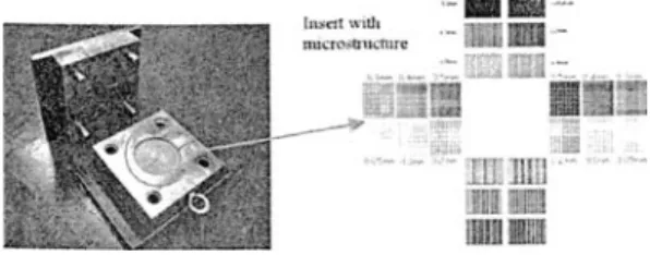
The microstructure design is based on micro-grooves. The micro structure consists of three type s: rectangular groove row, square groove array and circular groove array. The microstructure size in-cludes 0.05 rom, 0.1 rom, 0.2 rom, 0 .3 rom, 0.4 rom and 0.5 mm (Fig. 1).
2.3Mold Insert Fabrication
Our photolithography process involves photomask fabrication , wafer cleaning, spin coating, soft baking, exposure , post-exp osure baking, developing and hard baking.
h~t\\ ,rJl n u,"rOloC! u~-nu c
.1lIU.-Fig. I. Mold used for hot embossing .
A high-resolution transparency was used as the mask in photolithography. A silicon wafe r was used as the substrate. The wafer surface was cleaned with a 4: I HzSOJHzOz mixture for 10 minutes at 120 °C to remo ve organic contaminants. The w afer surface was rinsed using deionized (DI) water until the water res istance was larger than 8
n.
A 50: 1 HzOIHF step for 10 minutes at room temperature was applied to remove chemical oxides. The wafer surface was rinsed using deionized (DI) water again. After wafer cleaning, the substrate was spun, blown dry using heated nitrogen and then placed on a hot plate (120 °C for 3 minutes) to drive off any water vapor on the surface. This step is called dehydration baking.To improve the adhesion of resists to the silicon w afer, hexamethyldisilane (HM D S) is often applied. HMDS was applied to the wafer by spinning at room temperature. HMDS was dried by placin g the wafer on a hot plate for 2 minutes at 90 °C. The next step is spinning the res ist on to the w afer ; this should be done immediately after the HMDS application. A positive resist, AZ9260, was used in this study. The resist is dispensed onto the wafer while the wafer is spinn ing to produce a uniform layer on the wafer. The sp in speed of the spin coat er was increased to 500 rpm with an acceleration of 500 rpm/ s for 10 sec onds. For another 30 seconds, sp in speed and acceleration of the sp in coater were 300rpm and 300 rpm/s , respe ctively. The spin speed at this step determines the final thickness of the resist (a bout 50 IlID in this study ).
The next three steps in the lithography are the prebak e, wafer exposure and postexp osure bake (PEB). PEB wa s carried out at 90°C for I minute. After PEB, the substrate was again gradually cooled down to room temperature in order to minimize stress and prevent the resist from crack ing. Th e substrate was immersed into the beaker containing the developer ( 1:3 AZ400KIDI water) for about 5 minute s. After all the features were devel oped, the photoresist was rins ed in fresh DI water and blown dry with nitrogen. This gave rise to an AZ9 260 mold inse rt w ith positive features.
The final step in the photolithography process is the postbake which is designed to harden the resist and impro ve its etch res istance. Th e temperatur e is set at 11 O°C for 10 minutes. Th e post baked photoresist mold is not as strong as met al in withstanding the high pressure and temperature in injection molding. Isotropic reactive-ion etching (RIE) was applied in
C.H.Wu andH.C.Kuo!Journal ofMechanical Science and Technology 21(2007) 1477-1482 1479
Table I. Parameters of hot embossing and injection molding.
3. Results
(b) (a)
Embossing Embossing Embossing Demolding
Hot temp. force time terno.
embossing
120DC 15kN 180 sec 80DC
Injection Melt temp.
Injection
Mold temp. Packing
velocity pressure
molding
230DC 130 mrn/s 70DC 10MPa
In this study, the molding parameters can be divided into two parts, one is for hot embossing and the other is for injection molding. All process para-meters were based on material manufacture's sugge-stions. The parameters were shown in Table I.
2.5 Molding parameters
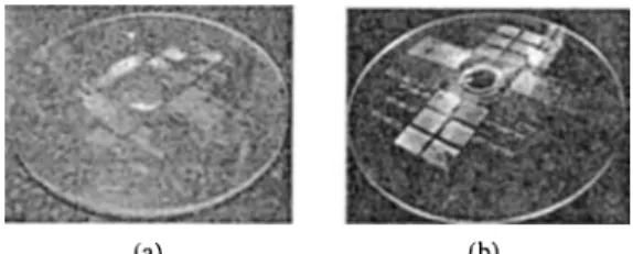
When the substrate is directly placed between the two mold halves, the embossed part shows incom-plete microstructure (Fig. 3a). To have a better embossing quality, a rubber pad was inserted between the upper mold half (movable one) and the substrate. The embossed part showed a better replication quality as shown in Fig. 3(b).
3.1 Comparison with hot embossed parts and injec-tion molded parts
2.4 Experimental setup
Injection molding operations were conducted with an injection molding machine (FANUC ROBOSHOT S-2000i50A). The machine can offer a clamping force up to 50 tons. The screw diameter is 22 mm and the maximum injection volume is 29 em', A hot embo-ssing machine (Fig. 2) was designed, assembled and calibrated. This machine mainly consists of a force frame which delivers the embossing force via a ballscrew connected with a servo motor. The force frame includes upper mold plate (movable) and lower mold plate (fixed). A mold (Fig. I), consisting of two mold halves, was installed between two mold plates. The movable half was fixed on the upper mold plate and the fixed half was fixed on the lower mold plate. Two cartridge heaters were installed on the fixed half which has a cavity at the center. The movable half has cooling channels inside to keep it at a specified mold temperature. A load cell was applied to monitor the pressing force. The measured force was also used to control the embossing at a specified pressing force. A thermocouple was installed directly on the PMMA substrate to get feedback on embossing temperature control.
this study. The photoresist mold acted as a pattern to electroplate the nickel mold. A thin gold layer was sputtered to create a conductive area for nickel growth.
Electroplating was conducted at 50°C with a pH of 4, and at a low current density of 4Ndm2in order to minimize internal stress in the nickel mold. After electroplating, the photoresist was stripped with an ultrasonic shaker. The nickel structure was placed in acetone and then rinsed withDrwater.
Fig. 3. Parts with (a) incomplete and (b) complete hot embossing.
Fig. 4. (a) Rectangular protrusion row and (b) square protru-sion arrays of mold insert.
(b) (a)
There are a lot of microstructures on the part. To simplify the analysis, only the rectangular groove of 0.2 mm and square groove array of 0.5 mm were
1480 C.H.Wu andH.C.Kuo / Journal ofMechanical Science and Technology 21(2007) 1477-1482
insert part
does not have a perfect shape due to incomplete filling. The embossed part has a larger wall width of square groove array than the injection molded part has (in comparison of Fig. 6 and Fig. 8). In this study, hot embossing seems to provide a better replication than injection molding does.
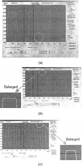
Rectangular groove rows of the hot embossed part and the injection molded part were measured. To measure the microstructure profile, a high performance surface profiler (XP-2, Ambios Technology, Inc.) was used. Dimensions of a rectangular groove row are defmed as shown in Fig. 9. From Table 2, it is found that both a hot embossed part and an injection molded part do not have a perfect replication of insert microstructure. The dimension deviations between the insert and the part are around 5-15 %. Itshows that these two methods can be applied to replicate the insert microstructure.
However, the shape of a hot embossed micro-structure has a better replication than the shape of an injection molded microstructure does. As shown in Fig. 10, the embossed microstructure has similar sharp corners as the insert does. However, the corners of an injection molded microstructure are smooth.
3.2 Microstructure Measurement (b) (b) (b) (a) (a) (a)
Fig. 5. (a) Topview and (b) sideview of rectangular groove rows of embossed part.
Fig. 7. (a) Topview and (b) sideview of rectangular groove rows of injection molded part.
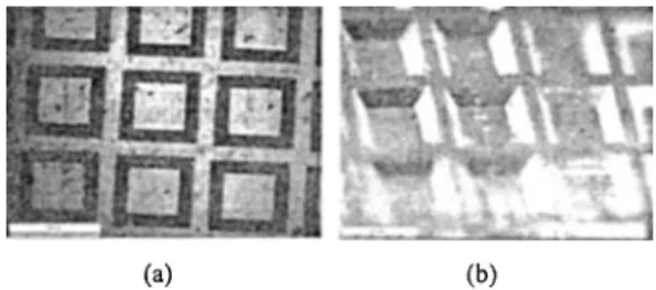
Fig. 6. (a) Topview and (b) stereoview of square groove arrays of embossed part.
measured and discussed. Firstly, the mold insert was observed using a microscope. The microstructures are shown in Fig. 4. The microstructures all show a taper angle because of isotropic reactive-ion etching (RIE). Rectangular groove row and square groove array of an embossed part are shown in Figs.5 and 6.
The injection molded part was also observed for comparison. Optimization methods were applied for both processes. Rectangular groove row and square groove array of an injection molded part are shown in Figs. 7 and 8. As shown in Fig. 7, the microstructure
Fig. 8. (a) Topview and (b) stereoview of square groove arrays of injection molded part.
(a) (b)
Fig. 9. Schematic illustration of title of the rectangular groove rows.
Table 2. Dimensions of rectangular groove row. Locals of
Insert Embossed part Injection
microstructure moldedpart
Width ofline (urn) 105.1 89.4 93.6
C.H.Wu and H.C.Kuo /Journal ojMechanical Science and Technology 21(2007) 1477-1482 1481
Table 3. Parameters set of single factor experiment.
(c) (;II) 1.:0 130 EJl1l_",.tDlt'(_c) (a) 1:0 lJO un L~Q 160 .c .
Factors Levell Level 2 Level 3
Embossing temp. 120 140 160 CC) Embossing force 10 15 20 (kN) Embossing time 60 180 240 (sec) Demolding temp. 70 80 90 CC) (a)
Fig. II. Results of single factor analysis by changing (a) embossing temperature, (b) embossing force, (c) embossing time and (d) demolding temperature.
(b) "0 :_ _ ._-~----10 1< zo :::nb:,~):r:;: ~('~(,-I!..~;;' (b) 80 • E78 ;:---..< , ~76
r
:j.
7.J ~ ---- ..._____ :,g,~ 'r- - - - .. 7() '~_. ~.• . -70 7." 80 35 90 [)(,l1lo.-.ldDlatll':l1Jp(,J~rr("-l (d) (c)Fig. 10. Surface profiles of rectangular groove rows at the (a) insert, (b) embossed part and (c) injection molded part.
This phenomenon can be explained by sudden freezing while polymer contacts the cold groove wall. When the polymer flows into the groove, the skin layer quickly cools down. The frozen layer slows down and induces a smooth shape of microstructure. As for hot embossing, the polymer is strongly pushed into the groove by the embossing force. This action creates a better replication of microstructure.
3.3 Parameters analysis
Embossing temperature, embossing force, em-bossing time and demolding temperature are inves-tigated to study their effects on replication quality of a hot embossed part. The dimensions of rectangular groove row on insert were described in Fig. 9. The basic set of parameters for embossing temperature,
embossing force, embossing time and demolding temperature are 160°C, IOkN, 240 seconds and 70°C, respectively. In this study, parametric analysis is carried out by changing one factor at a time keeping the others constant as shown in Table 3. The depth of groove row on insert is 81.40 urn. The replication heights are shown in Fig. II.
The results show that embossing force has little influence on the replication quality in this study. It
can be explained that embossing force of 10 kN is enough for these experiments. Higher embossing force does not have better replication.Anappropriate embossing temperature gives a best replication. Optimization is necessary for setting a best em-bossing temperature. However, the polymer can be further pushed into the micro-groove by increasing embossing time. Higher demolding temperature induces more shrinkage after ejecting embossed part. Therefore, the replication height decreases with demolding temperature.
1482 C.H. Wu and H.C.Kuo / Journal ofMechanical Science and Technology21(2007) 1477-1482
4. Conclusions References
The main objective of this study is to investigate the micro-replication ability of hot embossing and injection molding. Some conclusions can be drawn from the experimental analysis:
1. To have a good hot embossing process, the
machine and the mold should be aligned.
Misalignment creates incomplete embossing. The embossing force should be evenly applied on the polymer substrate.
2. From microscopic pictures, it shows that hot embossing provides a better replication than injection molding does.
3. To have better replication accuracy, both hot embossing and injection molding processes are in need of parametric optimization.
4. The hot embossed part has less shrinkage and warpage than the injection molded part.
5. In parametric study of hot embossing, replication height increases with embossing time and decreases with demolding temperature. The embossing force has little influence on replication quality if the force is large enough.
Acknowledgements
Technical assistance on the assembly of the hot embossing machine were enthusiastically provided by Wen-Fang Chen of Precision Machinery Research Center, Taiwan.
[1] Yi-Je Juang, L.J. Lee and K.W. Koelling, Hot Embossing in Microfabrication. Part I: Experi-mental, Polymer Engineering and Science. 42 (2002) 539-550.
[2]H.Becker and U. Heim, Hot embossing as a method for the fabrication of polymer high aspect ratio structures, Sensors and Actuators. 83 (2000)
130-135.
[3] D. Yao and BJ. Kim, Simulation of the filling process in micro channels for polymeric materials, Micromech. Microeng.12 (2002) 604-610.
[4] R.J. Wimberger-Fried1, Injection Molding of Sub-mum Grating Optical Elements, Injection Molding Technol.4 (2000) 78-83.
[5]
x-r.
Shen, Li-Wei Pan and Liwei Lin, Microplastic embossing process: experimental and theoretical characterizations, Sensors and ActuatorsA. 97-98 (2002) 428-433.[6] C.-R. Lin, R.-H. Chen, C. Hung, Preventing non-uniform shrinkage in open-die hot embossing of PMMA microstructures, Journal of Materials Processing Technology. 140 (2003) 173-178. [7] R.W. Jaszewski, H. Schift, 1. Gobrecht and P. Smith,
Hot embossing in polymers as a direct way to pattern resist, Microelectronic Engineering. 41/42 (1998) 575-578.
[8] M.T. Gale, C. Gimkiewicz, S. Obi, M. Schnieper, J. Sochtig, H. Thiele, S. Westenhofer, Replication technology for optical microsystems, Optics and Lasers in Engineering.43 (2005) 373-386.