國
立
交
通
大
學
資訊科學與工程研究所
碩
士
論
文
磁 振 造 影 腦 模 板 之 客 製 化 建 構
Construction of Customized Brain Template from
Magnetic Resonance Images
研 究 生:李國維
指導教授:陳永昇 博士
磁振造影腦模板之客製化建構
Construction of Customized Brain Template from
Magnetic Resonance Images
研 究 生:李國維 Student:Kuo-Wei Lee
指導教授:陳永昇 Advisor:Yong-Sheng Chen
國 立 交 通 大 學
資 訊 科 學 與 工 程 研 究 所
碩 士 論 文
A ThesisSubmitted to Institute of Computer Science and Engineering College of Computer Science
National Chiao Tung University in partial Fulfillment of the Requirements
for the Degree of Master
in
Computer Science August 2011
Hsinchu, Taiwan, Republic of China
摘要 腦部的磁振造影技術 (MRI),已被廣泛的使用在研究人類的腦部結構上,腦 模板 (template) 提供一個共同對位 (registration) 的標準空間,做為分析腦 部結構和比較腦部結構差異的基準。然而,對於一個不適當的腦模板空間,可能 會造成受測者的磁振造影影像需要過大的空間形變,才能對位到腦模板上,對位 後的成像容易會產生較大的誤差,對於研究分析特定族群的腦部結構,如何建構 一個無偏頗 (unbiased) 的腦模板是必要的。 此研究的主要目的是發展一個標準的建構客製化腦模板 (customized brain template) 流程。首先,我們會運用影像分析,將所有的受測者影像,截 取出純腦 (brain-only) 結構影像和不同腦組織 (tissue) 影像。接著,我們會 選取一個參考影像當作起始的腦模板空間,藉由腦模板和受測者影像之間反覆性 的影像對位流程,逐步的優化該選取的起始腦模板影像,並得到一個代表性的影 像 (representative image)。最後,將所有的受測者影像對位到此代表性影像 亦為腦模板空間,在平均所有對位到該空間的影像後即可得到腦模板影像。 在此研究中,我們利用 216 個正常受測者 (normal subject) 的影像,在台 灣建立一組腦模板稱為 BTT216。在和 ICBM152 腦模板的評比中,這 216 個受測 者影像對位到不同的腦模板後的成像,BTT216 提供較高的影像相關性
(correlation)。在平均形變量 (magnitude of deformation) 的評比上,BTT216 亦提供較小的形變差異。除此之外,我們針對特定的研究族群 (study-specific) 建立該族群的腦模板,例如不同性別和年齡層的腦模板,在評比中亦顯示此特定 的腦模板影像相較於其他腦模板提供較好的對位正規化空間。
我們的研究中,建立一個標準的建構腦模板流程,並針對特定族群所建立的 客製化腦模板,提供一個更佳的對位空間。
誌謝 首要感謝陳永昇老師這兩年來的指導,研究所的兩年中,從老師的專業領域 學習如何做好研究,老師常常告訴我們一些學習態度,也很關心學生平時的生活 狀況並且時常鼓勵我們,此外也要感謝陳麗芬老師,在每次的討論中給我許多的 建議,提供不同的研究思考或做法增加我研究的廣度,讓我的研究更加順利,在 兩位老師的指導下,兩年的研究生活只能說我真的太幸運了。 另外要感謝這兩年曾經一起學習、玩樂和鼓勵的朋友們,無論是實驗室的學 長姐、學弟妹、小助理們,亦或是實驗室外的同學和朋友,讓我的研究生活更充 實有趣。最重要的當然還有一起同甘共苦的夥伴們,這兩年一起吃喝玩樂,熬夜 努力,彼此打氣,謝謝大家帶給我兩年滿滿的回憶。
Construction of Customized Brain Template
from Magnetic Resonance Images
A thesis presented by
Kuo-Wei Lee
to
Institute of Computer Science and Engineering
College of Computer Science
in partial fulfillment of the requirements for the degree of
Master in the subject of
Computer Science
National Chiao Tung University Hsinchu, Taiwan
Construction of Customized Brain Template from Magnetic Resonance Images
Copyright c 2011 by
Abstract
The magnetic resonance imaging (MRI) of brain images has been widely used to re-veal the structure of human brain. A template space or template image provided a standard space to analyse brain structure or compare the differences among subject groups. How-ever, large spatial transformation due to improper template space may lead to large artifact of brain structures in the warped brain image. Therefore, how to construct an unbiased brain template suitable for specific studies is essential to structural brain analysis.
The main purpose of this study aims at the development of a standard procedure for constructing MRI customized brain template. At first, we applied image analysis to all subject images to segment T1 image into different brain tissues. Secondly, we selected a reference image as the initial template space and applied an iterative registration procedure, including affine and non-rigid transformation, to gradually refined the template space and obtained a representative image. Then we spatially normalized all subject images to this representative image and averaged the warped images to obtain brain template.
This study constructed brain templates in Taiwan from 216 normal subject images (BTT216), including brain-only, whole-brain, grey matter, white matter, and cerebrospinal fluid templates. In addition, we constructed the template images for study-specific sub-ject images, such as gender templates and different age-group templates. The evaluation method showed higher image correlation of warped images in BTT216 template rather than ICBM152 template. The average magnitude of deformation field was also shown in lower variation between BTT216 and subject images. The results of correlation shown in high similarity between study-specific template image and warped subject images which is nor-malized into the study-specific template space.
The customized brain template provides a better common space for brain structure anal-ysis. The proposed method could be used as a standard procedure for brain template con-struction.
Contents
List of Figures v List of Tables vii 1 Introduction 1
1.1 Background . . . 2
1.1.1 Magnetic resonance imaging (MRI) . . . 2
1.1.2 Brain Template . . . 2
1.2 Related Work . . . 4
1.3 Thesis Scope . . . 9
1.4 Thesis Organization . . . 9
2 Proposed Methods of Brain Template Construction 11 2.1 Introduction . . . 12
2.2 Tissue Segmentation . . . 14
2.2.1 Brain Extraction . . . 15
2.2.2 Inhomogeneity Correction . . . 15
2.2.3 Brain Tissue Segmentation . . . 16
2.3 Template Space Construction . . . 18
2.3.1 Initial Reference Image . . . 18
2.3.2 Representative Image . . . 19
2.3.3 Image Registration . . . 20
2.3.4 Iterative Registration . . . 21
2.3.5 Stopping Criterion . . . 23
2.3.6 Image Interpolation . . . 25
2.3.7 Image Outlier Removing . . . 26
2.4 Template Image Construction . . . 28
2.4.1 Customized Brain Template . . . 28
2.4.2 Whole-brain and Brain Tissue Template . . . 29
2.5 Construction of Study-specific Template Image . . . 29
2.6 Detailed Flowchart of Brain Template Construction . . . 31 iii
3 Evaluation of Brain Templates 33
3.1 Introduction . . . 34
3.2 Evaluation Using Image Intensity . . . 34
3.3 Evaluation by Deformation Field from Non-rigid Registration . . . 36
4 Experimental Results 39 4.1 Materials of MRI Brain Images . . . 40
4.2 Construction of Brain Templates . . . 41
4.2.1 Representative Brain Image (Template Space) . . . 41
4.2.2 Outlier Brain Images . . . 43
4.2.3 Average Brain Template Image . . . 43
4.2.4 Brain Tissue Template Image . . . 46
4.2.5 Study Specific Brain Template Image . . . 47
4.3 Evaluations of Brain Templates . . . 50
4.3.1 BTT216 template v.s. ICBM152 template . . . 50
4.3.2 Bisexual template v.s. Gender template . . . 52
4.3.3 Age-Group Template . . . 53
5 Discussion 59 5.1 Comparison between Customized Template and ICBM152 . . . 60
5.1.1 Correlation between Warped Subject Images . . . 60
5.1.2 Deformation Field from Individual Brains to Templates . . . 60
5.2 The Influence of Initial Selected Reference Image . . . 61
5.3 Study Specific Templates . . . 63
5.3.1 Gender Templates . . . 63
5.3.2 Template for Age Group . . . 65 6 Conclusions 69 Bibliography 71
List of Figures
1.1 Usage of template image . . . 3
1.2 Talairach atlas . . . 5
1.3 Related well-know template . . . 7
1.4 Chinese brain template . . . 8
2.1 Overview of template construction procedure . . . 12
2.2 Procedures of tissue segmentation . . . 14
2.3 Effect of the procedure of tissue segmentation . . . 16
2.4 Brief flow chart of brain template space construction . . . 17
2.5 Display of image registration with affine and non-rigid registration . . . 22
2.6 Iterative refine representative image . . . 24
2.7 Steps of image interpolation . . . 27
2.8 The outlier factors and outlier criteria . . . 28
2.9 Brief flow chart of brain-tissue template construction . . . 30
2.10 Detailed Flowchart of Brain Template Construction . . . 32
3.1 Landmarks . . . 38
4.1 Initial reference subject image . . . 41
4.2 The representative image through iterative registration . . . 42
4.3 The convergence of iterative registration . . . 43
4.4 The outlier images . . . 44
4.5 The average template image through iterative registration . . . 45
4.6 The different kinds of brain tissue template space and image . . . 46
4.7 The customized template based on gender group . . . 48
4.8 The customized template based on age group . . . 49
4.9 The standard deviation of warped image intensity difference per voxels . . . 54
4.10 Intensity standard deviation of warped image registered to ICBM152 template 55 4.11 Standard deviation of deformation field . . . 56
4.12 The average correlation of different age group subjects mapping into dif-ferent age template . . . 57
5.1 Template constructed from different initial reference images . . . 62 5.2 Total intracranial volume (TIV) of gender in different study group . . . 65 5.3 Total intracranial volume (TIV) of different genders and ages . . . 66
List of Tables
3.1 Landmark labelled position . . . 37 4.1 Number of subjects from the database . . . 40 4.2 Average and standard deviation of age from the database . . . 40 4.3 Average intensity correlation between the warped subject images in
differ-ent template spaces . . . 51 4.4 Average deformation magnitude . . . 51 4.5 Variance of the magnitude of deformation field obtained by normalized into
different template images . . . 52 4.6 The average correlation of warped images in bisexual average template and
gender templates . . . 53 4.7 The average magnitude (mm) of deformation field from non-rigid
registra-tion to bisexual average template and gender templates . . . 53 5.1 Correlation between representative image of different initial reference . . . 63 5.2 Correlation between template image of different initial reference . . . 63 5.3 Total intracranial volume (TIV) of different gender . . . 64 5.4 Total intracranial volume (TIV) of different age group . . . 67
Chapter 1
Introduction
2 Introduction
1.1
Background
1.1.1
Magnetic resonance imaging (MRI)
Magnetic resonance imaging (MRI) is a medical imaging technique, which is used in visualizing of the inside structure of organisms without physically intrusion. A magnetic resonance imaging instrument uses powerful magnets to polarize and excite hydrogen nu-clei in water molecules in human tissue, producing a detectable signal which is spatially encoded resulting in images of the body. MRI provides high contrast between the different soft tissues of the body and commonly be used for studying the structure of human brain.
1.1.2
Brain Template
The structure of human brain is naturally different for each individual subjects. Dif-ferent gender had been verified with variation in brain structure [16] [9]. Study of Good, Catriona D. et al. also showed the effectiveness of handedness [9]. The inter-ethnic dif-ference of brain structure is confirmed by the study of Zilles et al. [23]. Besides, different nurture factors could also affect the individual structural variability, such as the effect with human growing [3]. The brain volume is growing from youth to young adult and the vol-ume will start shrinking. Damage and disease may affect the brain structure,too [2].
The difference of MRI scanning environment could also obtained different images from different setting parameters of scanning machines. The MRI images could be in different dimensions or voxel size. In other words, the MRI images locate in different stereotaxic coordinate system with inconsistent orientation. Even we obtain the subject images form the same scanning machine with consistent setting parameters, the testing subjects may have a little movement in scanning process. This reason could also visualize the image in different orientation.
In order to the structure differences between each individual subjects from MRI, a stan-dard stereotaxic coordinate system of human brain structural space should be provided.
Re-1.1 Background 3
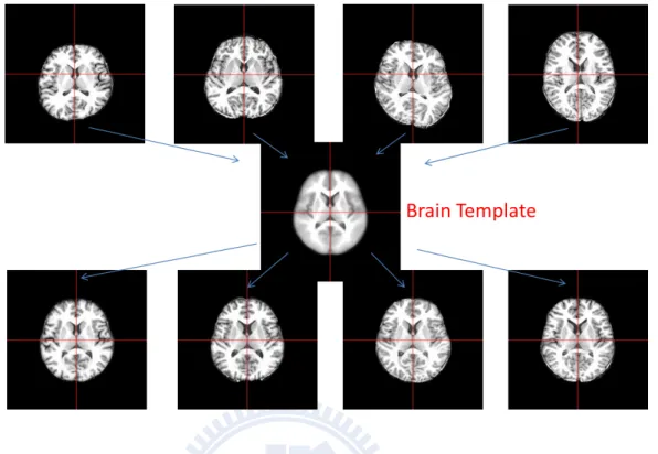
Figure 1.1: Usage of template image. To compare the different MRI images from scanning machine, template image provides a common space of structural coordinate system.
searchers could normalize each individual subject image to this template space as shown in Fig, 1.1 for further analysis or comparison. Due to the subjects may obtain from in-consistent sources or scan by different MRI machine environment and the brain structure of each subject may be affected by different nature or nurture factors. Each individual subject image from subject group should aligns to the same template space which is well-represented for that subject group. A proper well-represented template space could reduce the distortion from the registration procedure. Large distortion may increase the possibility of registration inaccuracy and bias the analysis result. Most researches apply the subject group images into the well-known template space, such as MNI305 and ICBM152. But these well-known template was constructed from the western subject images. We have already known that different ethnicity with significant difference of brain structure [23]. Constructing a reliable template space or template image have became an issue to study.
4 Introduction
1.2
Related Work
Talairach atlas
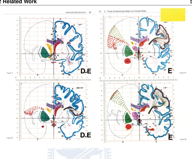
In 1988, Talairach atlas was manually labeled of brain structure based on a 60-year-old French female [19]. This stereotaxic coordinate system manual is based on two landmarks, the anterior commissure (AC) and posterior commissure (PC). AC point is set as the orien-tation of the coordinate system. AC-PC line lie on the mid-saggital plane and also a straight line in horizontal direction. Fig 1.2 shows four slices of verticofrontal sections in Talairach atlas. As mapping to Talairach atlas, researchers also label AC and PC point on the subject image to do the initial alignment with rotation and translation.
Talairach atlas provides the structure coordinate system with relative location of brain structure in early year, but it also with some errors as template space. First, the atlas is biased to an individual elder woman. The image registration may contain large distortion for the variation from different structure of brain. Secondly, the registration to the Talairach atlas apply with manual landmark mapping which may contains the artificial error. On the other hand, the Talairach atlas assumes that the brain structure is symmetric, which seems to be irrational with the understanding of brain structure now.
MNI305
In 1992, Montreal Neurological Institute (MNI) created an average of 305 subject im-ages mapping to the Talairach atlas called MNI305 [7] [15]. Fig. 1.3(a) displays the tem-plate image. This temtem-plate created based on the coordinate system of Talairach atlas. The construction procedure consisted of two stages. At first, 241 brain images were registered to Talairach coordinates and averaged to become the first-pass image. The registration was achieved by aligning several manually-specified landmarks of 241 brain images together by 9-parameter linear transformation. In the second stage, 305 normal MRI scans were linear normalized to the first-pass image using automatic fitting strategy to reduce the artificial error.
1.2 Related Work 5
Figure 1.2: Talairach atlas. Talairach atlas of the human brain was introduced in 1988 by Talairach and Tournoux. They defined a standard coordinate system based on dissection of an 60-year-old French female’s brain. This figure shows four slices of verticofrontal sections in Talairach atlas.
(Graphic source : http://homepages.nyu.edu/∼ef725/amygdala.html)
MNI305 template is obvious in low contrast from Fig. 1.3(a). The local structure could not been verified clearly (from Fig. 1.3(a)). It may attribute to the contrast of subject images or the registration technique did not provide high accuracy.
Colin27
To reduce the blurred condition of local structure from MNI305, a model was con-structed by an individual subject - Colin Holmes, who had scanned 27 times within 3 months in 1998 [10]. The average image of these 27 images which normalized to MNI305
6 Introduction
template shown in Fig. 1.3(b). Even Colin27 provided in high quality of template image, the template image is biased to this individual source object structure.
ICBM152 and ICBM452
In 1993, ICBM (International Consortium for Brain Mapping) was formed with four research sites: University of California, Los Angeles (UCLA), Montreal Neurologic In-stitute (MNI), University of Texas at San Antonio (UTSA), and the InIn-stitute of Medicine, Juelich/Heinrich Heine University - Germany. This ICBM projects is committed to de-velop a probabilistic reference system for the human brain. In 2001, The ICBM is template is wildly accepted as a standard template image which was constructed with 152 T1 normal subject images in higher contrast [14]. Each individual subject image was linearly regis-tered to the MNI305 template and the average template image is constructed and shown in Fig. 1.3(c). The advantage of this template model is that it exhibits better contrast than MNI305 and also do not bias to any specific individual subjects. Followed by the im-provement of techniques in MRI scanning and registration methods, ICBM still working on creating brain template. The registration method with non-linear technique has started to apply since 2002 and the building procedure has included six iteration times of registration which is show in Fig. 1.3(d) called ICBM152.
The ICBM template provides high resolution T1 images from age 19 to 90 in half males and females with high accuracy registration and still working on template construction. ICBM452 had published and constructed by 452 subjects. Even though, the template was constructed based on western human brain. As Zilles et al. had proved the inter-ethnic dif-ference [23], we should not apply ICBM template as our common space of brain mapping and eliminate the possible of large distortion in image registration.
1.2 Related Work 7
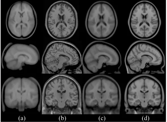
Figure 1.3: Related well-know template. (a) MNI305 : Constructed by Montreal Neuro-logical Institute (MNI) by averaged 305 normal subjects images mapping to Talairach atlas. (b) Colin27 : Individual subject scanned 27 times within 3 months and averaged these 27 images which had normalized into MNI305. (c) Affine ICBM152 : An averaged image with 152 higher contrast of subject images which were linearly registered to MNI305 by entirely automatic technique. (d) ICBM152 : Improvement of Affine ICBM152 with non-linear registration.
8 Introduction
Chinese Brain Template
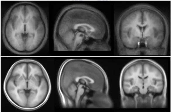
In 2007, the group of National Taiwan University (NTU) constructed a Chinese brain template using their developed software by 10 subject images [21]. This study also verify the difference between the western brain template and Chinese brain template. Fig. 1.4 shows their template image. As the number of subject images was not large enough, the template image is obvious blurry. In 2008, the group of National Chiao Tung University (NCTU) constructed the averaged brain template in 191 normal subject images [6]. The construction procedure selected a representative image from the subject group as initial ref-erence template image and used affine and non-rigid registration between refref-erence image and the whole subject images to refine the template image. The results is shown in Fig. 1.4.
Figure 1.4: Chinese brain template. The upper figure shows the template constructed by NTU in 2007. The lower figure shows thetemplate constructed by NCTU in 2008.
1.3 Thesis Scope 9
1.3
Thesis Scope
This study aims to construct a standard procedure of creating customized brain template based on the subject images. Most construction procedure refer to the well-known template as initial template space, such as ICBM template [12] [8]. As the well-known template was constructed based on different ethnicity, the template constructed by Taiwanese subject images should be convinced for our study group. We select the initial reference image from our subject images which has the smallest variation to other subject images. Our construction procedure use iterative refinement to obtain the final representative image as our template space. In order to the bias from initial reference image, we acquired the brain template image by averaged all subject images mapping to the template space.
The construction procedure could be applied to construct the brain-only, whole-brain, grey matter, white matter and cerebrospinal fluid template image. Each template image applied the procedure of tissue segmentation at first and constructed on the same template space with the same deformation.
After constructed the procedure, we could implement the template on study-specific subject group, such as different genders or ages to construct male/female template image or template in different groups of age.
1.4
Thesis Organization
In the following chapters, we will present our construction procedure, experimental re-sults, discussion and conclusion. In Chapter 2, we will describe our method of template construction and the evaluation method of our constructed template compared with differ-ent templates in Chapter 3. In Chapter 4, we will show the constructed template images and other experimental results. Then we will have a discussion about the experimental results in Chapter 5. Finally, in Chapter 6, we will make the conclusions.
Chapter 2
Proposed Methods of Brain Template
Construction
12 Proposed Methods of Brain Template Construction
Figure 2.1: Overview of template construction procedure. The figure shows the brief flow chart of template construction.
2.1
Introduction
Our research seeks to provide a standard procedure of constructing MRI brain template image based on any study specific subject image groups. The researchers could construct the brain template depend on their demands of study. The procedure of construction does not rely on any well-known brain template to reduce the bias and differences between subject group and the reference template which constructed from different subjects. Our procedure includes three major procedures:
1. Tissue segmentation
2. Template space construction 3. Template image construction
Figure 2.1 shows the overview of our construction procedure.
At first, we obtain the raw data images with whole-brain from MRI scanning machine. To make sure the construction procedure have the best accuracy, all raw data in the sub-ject group apply tissue segmentation. The procedures of tissue segmentation contain brain extraction to obtain the brain-only image which improves the accuracy of brain image regis-tration; correction of intensity inhomogeneity solves the problem of non-uniform intensity in the same brain tissue to acquire the images with better quality; brain-tissue segmentation separates the brain volume into grey matter, white matter and cerebrospinal fluid.
Second, we apply the images acquired from the procedure of tissue segmentation to construct the template space and the construction procedure is based on the brain-only
im-2.1 Introduction 13
ages. In the procedure of template space construction, we select an initial reference image as the initial template space. To refine this template space, we register all subject images to the template space and obtain an averaged transformation from these image registrations. The template space could be updated from an initial reference image into a representative image by applying the average transformation. The concept of refined the representative image could be performed in iterative registration. Iterative registration contain iterative affine registration and iterative non-rigid registration. Iterative affine registration refines the initial reference image with global shape of image and obtains an affine representative im-age. Iterative non-rigid registration refined the affine representative image with local struc-ture alignment. The final representative image through the refinement of iterative affine registration and iterative non-rigid registration is our constructive template space. As we have the average transformation for each iteration time of registration based on brain-only images, the brain tissue and whole-brain images could also apply the same transformation and refinement to obtain the representative images of whole-brain and brain tissue.
Finally, the initial reference image iterative updates into a representative image which stands for the template space of the subject group images in brain-only and the procedure also obtain the template spaces of whole-brain and brain tissue. We register all subject images of different brain tissue into each template space and average the warped images. The averaged of warped images from subject images, which register to each template space are the template images. These template images could be used for structural analysis of human brain.
14 Proposed Methods of Brain Template Construction
Figure 2.2: Procedures of tissue segmentation. The figure shows the flow chart of tissue segmentation. Brain extraction: Extracting the brain-only tissue improves the accuracy of brain image registration. Inhomogeneity correction: Non-uniform intensity correction is performed to acquire images with better qualities and contrast.Tissue segmentation: Separating the brain volume into three different tissues.
2.2
Tissue Segmentation
As MRI brain images obtained from the MRI scanning machine, there are some auto-matic procedures for tissue segmentation to help for the construction of template. Fig. 2.2 shows the flow chart with following procedures:
1. Brain extraction
2. Inhomogeneity Correction 3. Tissue segmentation
2.2 Tissue Segmentation 15
2.2.1
Brain Extraction
The raw MRI brain images provide the whole head information including brain skull, brain-tissue and other non-brain tissue. The brain skull and non-brain tissue may have the similar intensity level compared with brain-only image. To improve the accuracy of MRI brain image registration, the brain-only images support better image intensity informa-tion than whole-brain images [20]. In the procedure of template construcinforma-tion, we using the brain-only images to create the template space and template image. Before the construction procedure, each subject image apply brain extraction as the first step of tissue segmenta-tion. Our research obtain the brain-only area using mri-watershed tool [17] acquired from FreeSufer which provided automated brain reconstruction tool from MRI by Athinoula A. Martinos Center for Biomedical Imaging. Both brain-only template image and whole-brain template image could be constructed form our template construction procedure.
2.2.2
Inhomogeneity Correction
MRI technique visualizes the image of brain structure by the different magnetic field gradients cause from the different atom of brain structure. The raw MRI image shows that the same brain tissue may visualize in different intensity, because same tissue of brain may not receive the same MR signal frequency practically. The reason is usually attributed to poor radio frequency (RF) coil uniformity and gradient-driven eddy currents [18]. There-fore, it will cause MRI image having intensity inhomogeneity in the same brain tissue area. Due to intensity inhomogeneity, this study uses the technique of parametric Non-uniform intensity Normalization (N3) [18] provided by Dr. A. C. Evans at the Montreal Neurological Institute to correct the problem. N3 optimizes the intensity field based on the distribution iteratively. The intensity correction applies in both brain-only and whole-brain images as shown in Fig. 2.3. Intensity correction could also improve the performance of image registration and brain tissue segmentation that both techniques base on the image intensity information.
16 Proposed Methods of Brain Template Construction
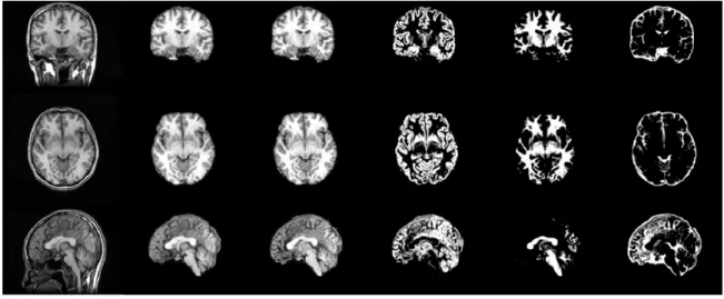
Figure 2.3: Effect of the procedure of tissue segmentation. This figure shows the effect from different tissue segmentation procedures in three different views of MRI brain im-age. From top to bottom are coronal view, horizontal view and sagittal view. From left to right are images of raw image; image with brain extraction; intensity correction after brain extraction; brain tissue of GM; brain tissue of WM; brain tissue of CSF. The brain tissue extracted from the brain-only image followed with correction of intensity inhomogeneity.
2.2.3
Brain Tissue Segmentation
Brain tissues general include grey matter (GM), white matter (WM) and cerebrospinal fluid (CSF). Different brain tissues contain distinct meanings in medical research. There-fore, grey matter, white matter and cerebrospinal fluid template image could also be con-structed for specific research. The extraction tool or algorithm separate brain tissue into three parts based on image intensity. Therefore, the extraction step follows the correction result of intensity by N3 from the brain-only image. This study use the tool - FAST [22] (FMRIB’s Automated Segmentation Tool) version 4.1 developed by University of Oxford Centre for Functional MRI of the Brain (FMRIB) to obtain the brain tissue.
2.2 Tissue Segmentation 17
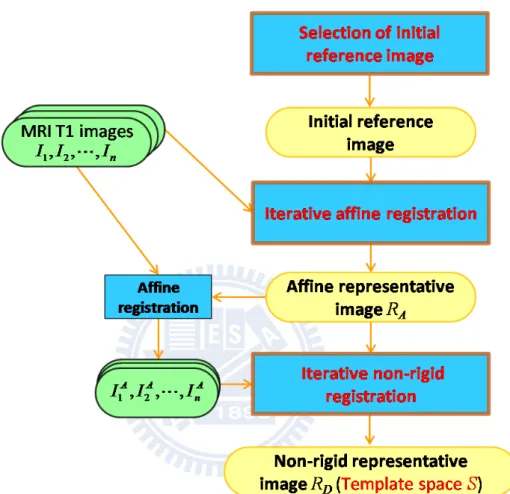
Figure 2.4: Brief flow chart of brain template space constriction. This flow chart shows the brief procedure of brain template space construction. The procedure with three major parts: Selection of initial reference image: Find a subject image from subject group which has the minimum variation to other subjects as initial reference image. Iterative affine registration: Use affine registration to refine the global shape of representative image of template space. Iterative non-rigid registration: Use non-rigid registration updating the representative image following the iterative affine procedure and refining the brain tissue structure.
18 Proposed Methods of Brain Template Construction
2.3
Template Space Construction
In this study, we use MRI T1 brain-only images as input, because brain-only images provide better contrast of image registration than whole-brain image. All input images had been preprocessed by the steps described in the previous section of Chapter 2.2. The raw data image will do brain extraction at first, then solve the intensity inhomogeneity by N3 tool. Fig. 2.4 shows the brief procedure of creating customized template. The input subject group could be any customized subjects depending on specific study. An initial reference image will be selected from the subject group as a representative image of this group. Although the template will bias to the chosen one, iterative registration to construct the template should reduce the influence of the initial reference image. The construction procedure will create a representative image which represents for all the subjects from the subjects group. This representative image could also be seen as a template space. Any analysis or comparison could be implemented by normalize the subjects to this standard template space.
2.3.1
Initial Reference Image
The initial reference image is set as an initial template space for image registration. Most construction procedure choosed the well-known template such as ICBM152 as the initial reference [12]. Nevertheless, most well-known template was constructed from the Caucasians. The brain structure between different ethnicity was verified with inconsistency [23]. Choosing a representative image selected from the subject images as initial reference is also another choice [8]. The selection strategy in our study depend on the customized template which we want to construct.
As constructed the whole-subject template image, we choose an initial representative image from the subject images which has the lowest variance described below. The se-lection should reduce the bias rather than random sese-lection from the subject images. To find this initial reference image R0, we use pair-wise non-rigid registration to calculate the
2.3 Template Space Construction 19
variance of the magnitude of deformation field Di,j from source image i to target image
j. Non-rigid registration aligns the local structure of brain image. More description of non-rigid registration will describe in Chapter 2.3.3. The following equation 2.1 shows the criterion of image selection:
R0 = arg min
i {var(kDi,j(x)k) | ∀j 6= i, x ∈ brain coordinate}. (2.1)
Because the pair-wise non-rigid registration is very time consuming (for 216 subject im-ages, the pair-wise registration cost about two months), we used the same initial represen-tative image as in Chang [6] which was selected from 191 of the 216 subjects in our study according to the above-mentioned selection criterion.
When we construct the study-specific template, the whole-subject template image would is used as the initial representative image. The whole-group template not only can save the time of pair-wise image registration to find the image with the smallest variation but also can serve as a good initial template image to construct different study-specific templates. The comparison of study-specific templates should be more reasonable in this way.
2.3.2
Representative Image
This study aims to construct a customized template space and template image based on any demanding subject group which the researchers want to analyse. As we select an initial reference image being initial template space, the template construction procedure will refine the reference image into a representative image which is also the template space for the subject group. The representative image provides the template space information. After we construct the represented image (template space), all subject image could register to the template space and create the average template image. We use the brain-only image as our representative image rather than whole-brain image due to the similarity of intensity from the brain tissue and brain skull. Because brain registration is based on the intensity of brain image, the brain-only image provide higher registration accuracy. Even only the brain-only image will be considered as the target to be refined, other brain image obtained
20 Proposed Methods of Brain Template Construction
from the preprocessing steps could also apply the same refined transformation and construct the template. The result types of representative image will include brain-only, whole-brain, grey matter, white matter and cerebrospinal fluid images.
2.3.3
Image Registration
The image registration based on the transformation of each voxel from source image to target image. The registration process includes two major parts: global affine normaliza-tion TAand non-rigid transformation TN. Affine registration do the global shape alignment.
Non-rigid registration do the alignment of local structure of brain. The effect of different registration methods shows in Fig. 2.5. For each grid point p in source image and corre-spond location q in target image, the following equation present the transformed relation:
q = TA(p) + TN(TA(p)) (2.2)
Affine Registration
Affine normalization aligns the global shape from the source image to the target image with 12 transform parameters including translation (tx,ty,tz), rotation (θx,θy,θz), scaling
(sx,sy,sz) and shearing (kxy,kxz,kyz) for each contains in three directions. For Each grid
point p of source image maps to the corresponding location q in target image, the trans-formation could use a transform matrix M to present the mapping relation. The relation is shown in equation 2.3 and the matrix M also shown below. In this study, University of Oxford’s FMRIB Software Library (FSL) provided FMRIBs Linear Image Registration Tool (FLIRT) [11] which be used in the procedure for affine registration.
2.3 Template Space Construction 21
and the transform affine transformation matrix M with a rotation matrix Rxyz:
M = 1 kxy kxz 0 0 1 kyz 0 0 0 1 0 0 0 0 0 sx 0 0 0 0 sy 0 0 0 0 sz 0 0 0 0 1 0 Rxyz 0 0 0 0 0 1 1 0 0 tx 0 1 0 ty 0 0 1 tz 0 0 0 1 Rxyz = R(θx)R(θy)R(θz) Non-rigid Registration
Non-rigid registration mainly solves the problem of inter-brain tissue misalignment af-ter we align the global shape of image from affine normalization. The spatial mapping used in our study is based on a set of Wendlands radial basis functions (RBFs) with different lev-els of support extents [13]. RBFs model the deformation field D of the brain image from source image to target image. The following equation 2.4 shows the relation of mapping from source image to target image.
q = TN(TA(p)) = p + D(p) (2.4)
In the evaluation of image registration from a source image to a target image, each coordi-nate location in the deformation field represents the deformation vector with the magnitude and direction of deformation. By the average and variance of magnitude, we could observe the variation between source image and target image. We could also use the deformation field to evaluate the accuracy of image registration.
2.3.4
Iterative Registration
The initial selected reference image is seen as the first representative image for the sub-ject group because it has the minimum variance with other subsub-ject images. Nevertheless, the template space will bias to this selected one if we construct the template at the selected
22 Proposed Methods of Brain Template Construction
Figure 2.5: Display of image registration with affine and non-rigid registration. (a) Source image. (b) Target image. (c) Mapped from source image into target image by affine registration. (d) Apply non-rigid registration from (c) to (b). In other words, mapped source image into target image with affine registration and non-rigid registration.
space. The procedure of constructed template in iterative registration could refine the tem-plate space and reduce the influence of initial reference image. The constructed procedure is shown in Fig. 2.6 in iterative steps.
At first, initial reference image R0 is selected from the subject group. Without using
averaging subject group images as initial image, the individual MRI scan image provides better contrasting information and clearer brain anatomical local structures. This could make registration parameters and cost functions more precise and increase the accuracy of registration. Using automatic registration method, this reference image could optimize to become a representative image.
The creating procedure of registration divides into affine registration part and non-rigid registration part. In affine registration, all subject images will do translation and rotation to the initial template space at first because the subject may have a little movement when
2.3 Template Space Construction 23
they did MRI scanning. It should not be considered as the factor of inconsistent of brain structure. After the alignment with translation and rotation, the reference image maps to each subject images in affine registration with scaling and shearing, which solves the problem of global shape difference. The registration procedure in iteration i will obtain n subjects’ transform matrices Mji where j from 1 to n which including the difference information between the reference image and each subject. As we want to optimize the reference image to be a well representative image of subject group, this purpose could implement by applying the average transform matrix M on the reference image to update the reference image RA (Equation 2.5). The affine registration with scaling and shearing
could do iteratively and the representative image will refine iteratively until steady. This concept could also be used in non-rigid registration for alignment of local structure. The updating representative image RAfrom the iterative affine registration could be the initial
as the non-rigid registration. The non-rigid registration deformation field, Di handles the
inter-brain alignment. The iterative non-rigid registration procedure is similar to affine registration as in equation 2.6. The representative image could be updated iteratively until in a steady state RD. The final representative image RD is also the final determinative
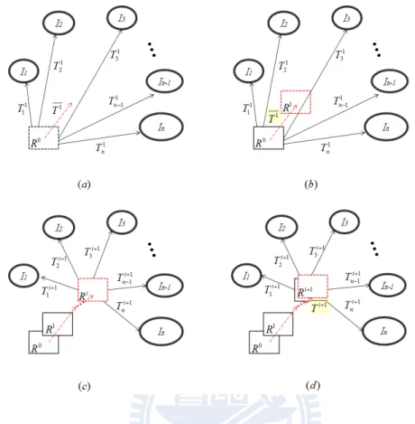
templates space S. Ri+1A = Mi+1× Ri A for Mi = ( n X j=1 Mji)/n (2.5) Ri+1D = ( RA+ Di+1(RA) if i = 0 Ri D+ Di+1(RiD) if i > 0 for Di = ( n X j=1 Dij)/n (2.6)
2.3.5
Stopping Criterion
For each iteration, the representative image Ri−1 is refined to a new representative image Ri. The iteration of this representative will converge into a stable state. In general, iteration times should be stopped in finite iterations. As the average affine transformation matrix or average deformation field in a stable state, transformation for the image would be slight and small. In other words, the variance of the intensity of representative image
24 Proposed Methods of Brain Template Construction
Figure 2.6: Iterative refine representative image. This flow chart shows updating proce-dure for represented image from (a) to (d). R : representative image; I : individual subject image; T : transformation of registration (As in affine registration, T should be a affine transformation matrix M . In non-rigid registration, T would be deformation field D); T : average of transformation; i : iteration time; n : subject numbers.
should be stable. At first the average intensity difference ID per voxel would be computed and recorded shown in equation 2.7. Each value shows the extent of variation in iteration time of i − 1 and i.Due to the registration will not steady, the image intensity still have a little different. We set the slope of average voxel intensity difference IDi as the threshold for stopping iterative registration. Equation 2.8 shows the slope IDP(i,i+1) of difference
between IDi and IDi+1
IDi = (
k
X
j=1
)|Ris(xj, yj, zj) − Ri−1s (xj, yj, zj)|)/k (2.7)
IDP(i,i+1) = (IDi− IDi+1)/IDi
2.3 Template Space Construction 25
2.3.6
Image Interpolation
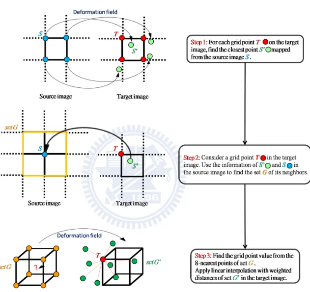
For image registration, the output will obtain an affine transformation matrix M in affine registration or a deformation field D in non-rigid registration. The transformation estimate the mapping from location of source image into the corresponding location in target image. The warped image will be created by the technique of image interpolation. In affine registration, we transform the source image into target image space by applying affine transformation matrix using FLIRT [11]. In non-rigid registration, the deformation filed is not a grid point to grid point mapping. In other words, each grid point of source image may not actually map to a grid point in the target image as in Fig. 2.7 of Step 1. We will use following method to do interpolation and create the warped image.
The interpolation steps are shown in Fig. 2.7. To construct the target image, the in-tensity information from source image is necessary. Due to the mapping relation from the deformation field, we obtain the intensity information from the grid point in source image and the mapping location in target image. Then we will have the information of the inten-sity in target image even non-uniform distribute in the target image coordinate. To obtain the value of each grid point in target image, the concept of our interpolation method is used intensity and distance value of nearest neighbors. How to find the nearest neighbors without searching for the whole-image becomes an issue.
At first, considering a grid point T in target image and find a close location S0deforms from a grid point S of source image. In source image, set the grid point S as center and find a cube contain enough grid point for interpolation. Collected these grid point into the set G as in Fig. 2.7 of Step 2. The size of the cube may be variant depends on the numbers of neighbors we needed. In this study, we use nearest eight neighbors for image interpolation. After found a set G of grid points from source image, G0 record the coordinate location form the deformation field D in target image. From set G0, select eight nearest neighbors and calculate the value of grid point T (Equation 2.12) using the inverse from distance as
26 Proposed Methods of Brain Template Construction weighted (Equation 2.11). G = {(xj, yj, zj) | i = 1, ..., n} (2.9) G0 = {D(xj, yj, zj) | i = 1, ..., n} (2.10) w(xj, yj, zj) = 1/dist(D(xj, yj, zj), T ) (2.11) v(T ) = P 1 iw(xi, yi, zi) X i w(xi, yi, zi) × v(xi, yi, zi) (2.12)
2.3.7
Image Outlier Removing
The construction procedure input all needed subject images to create the template space and template image. If one of the input image with great deform form representative image to this one, the result template may affect by this outlier especially when the subject num-bers are not large enough. To ensure the template could not only represent the subject group but also be in a standard coordinate system, the procedure should add criteria to remove the outlier of subject image.
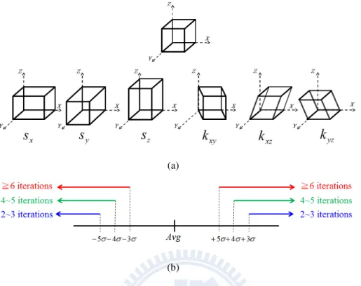
In this study, the outliers consider transformation effect from scaling and shearing in affine transform. Translation and rotation align two images to the same coordinate space. Deformation of non-rigid registration reduces the brain tissue structure difference. The last two effects are not stand as outlier generally. Both scaling and shearing include 3 directions: Scale with x-axis, y-axis and z-axis, shear parallel to the x-axis by variable of y and z and shear parallel to the y-axis by variable of z (Figure 2.8(a) from left to right).
There are total six variables considered as outlier factors. Each registration between subject and representative image will obtain those six variables. Compute average and standard deviation for six outlier factors in each iteration time of affine registration. If any factors of the six variables out of range: average five times standard deviation in second and third iteration time, the subject will set as outlier. If any factors out of range: average four times standard deviation in fourth and fifth iteration time, the subject will also set as outlier. Finally, the criteria will set outlier which variable of factor is out of range: average
2.3 Template Space Construction 27
28 Proposed Methods of Brain Template Construction
(a)
(b)
Figure 2.8: The outlier factors and outlier criteria: (a)The outlier factors:Here are the considering outlier factors(coefficients) from affine registration which include scale in x,y,z-direction (sx,sy,sz) and shear parallel to the x-axis by variable of y and z (kxy,kxz)
and shear parallel to the y-axis by variable of z (kyz) (from left to right). (b) The outlier
criteria: The blue line shows the outlier range in 2ndand 3rditeration time. The green line
shows the outlier range in 4th and 5th iteration time. The blue line shows the outlier range
after 6th iteration time. The range is defined by the average value (Avg.) and standard
deviation (σ) in each of outlier factors.
three times standard deviation above sixth iteration time. The range setting also shows in Fig. 2.8(b).
2.4
Template Image Construction
2.4.1
Customized Brain Template
The iterative registration refine the initial reference image into a representative image which represents the template space for subject group. The template space provides the
2.5 Construction of Study-specific Template Image 29
coordinate information of local brain structure. We could transform all the subject images into this template space and average all warped images. The averaged image could provides the coordinate information of local brain and also information of whole-brain structure from all subject images.
2.4.2
Whole-brain and Brain Tissue Template
The construction brain template procedure based on the brain-only images. Each iter-ative registration obtain the average affine transformation matrix or average deformation field. We could apply these transformation on the whole-brain, grey matter, white matter and cerebrospinal fluid to obtain the brain tissue template space and template image. The application of averaged transformation in i times of iteration shows in equation 2.13 and equation 2.14. Fig. 2.9 shows the procedure of constructing whole brain and brain tissue template.
RA= Mi+1× Mi× · · · × M1× R0A (2.13)
RD = RA+ Di+1(Di(· · · D1(RA))) (2.14)
2.5
Construction of Study-specific Template Image
In addition to the template constructed for whole subject images, we can also construct the templates based on study-specific images. In this study, we considered different genders and ages of subject images to create the male template, female template, and templates in six different age ranges.
30 Proposed Methods of Brain Template Construction
Figure 2.9: Brief flow chart of brain-tissue template construction. This flow chart shows the brief procedure of brain-tissue template construction. The procedure of original tem-plate construction obtain the average affine transformation matrix and average deformation field as the first column. The whole-brain and brain tissue image could apply the same transformation to obtain the template space. All subject specific images transform into the template space and get the averaged template image.
Gender templates
The construction of male/female template creates from the whole male/female subject images. The whole-subject template image is chosen as the initial reference template as the initial of the representative image. The construction procedure is the same as the con-struction of the whole-subject template image which iteratively updates the representative template image.
Age-group templates
The whole subject images were divided into six groups each with 10 years according to the ages of subjects. The ages in the youngest group range from 14 to 19, and those in the oldest group range from 60 to 69. Each specific age-group templates was created only from the subject images with the specific age range. For the construction procedure of each template, the whole-subject template image was used as the initial representative image.
2.6 Detailed Flowchart of Brain Template Construction 31
2.6
Detailed Flowchart of Brain Template Construction
Fig. 2.10 shows the detailed flowchart of brain template construction. It mentions all the methods described in the previous of this chapter.
32 Proposed Methods of Brain Template Construction
Figure 2.10: Detailed Flowchart of Brain Template Construction. This figure shows the whole procedure of template construction which combined with three major parts of procedure: data analysis, template space construction and template image construction and each with detailed flowchart.
Chapter 3
34 Evaluation of Brain Templates
3.1
Introduction
As the template space and template image are constructed, there are some evaluations for testing our constructed template is well-represented as the subject groups. The compar-ison is focus on the difference between the template image and the subject image warped into the template space. As the difference is lower or the warping magnitude is smaller, the template had better representativeness. The well-known template could also be a compar-ison to make sure our constructed customized template is better. The template evaluation could be based on the following two factors:
1. The intensity of brain image
2. Deformation field from non-rigid registration
3.2
Evaluation Using Image Intensity
Considering the image intensity value, if the brain template is well-represented for the whole subject group, the close voxel coordinate between each subject images which have mapping into template space should have similar intensity value. The whole subject group images transform into our creating template space to do the following evaluative methods. This study uses intensity standard deviation for each voxel in warping image and intensity correlation for each warping image to evaluate the performance of our template.
Intensity standard deviation
For measuring the variance between warped images and template image in each coor-dinates, we consider the intensity of the same voxel coordinate between all warped images which obtain from all subject images register to the template space. If the template image improves the accuracy of registration, the intensity value of different warped images in the
3.2 Evaluation Using Image Intensity 35
same voxel coordinate should be close. Equation 3.1 shows the computing formula.
SD(x) = v u u t 1 n n X j=1 IS j (x)2− ( 1 n k X j=1 IS j(n))2 (3.1)
n is the subject number and IS
j(x) stands for the intensity of subject j in template space S
at coordinate x.
Small standard deviation represent all image transform to this template space in closer divergence. Because this measure is focused on the variance of each voxel coordinate, the result could also show where the larger difference is in which brain tissue structure.
Image correlation
Another measuring method computed the correlation between subject images and tem-plate image. Correlation shows the similarity of two images and equation 3.2 shows the computing formula. rAB = Pk i=1(Ai− A)(Bi− B) q Pk i=1(Ai− A)2 Pk i=1(Bi− B)2 (3.2) As A and B are two images, Ai (or Bi) stands for the intensity value of image A in
coordi-nate i. k is the voxel number of image without background (image intensity equals zero). In this study, we perform the correlation value between the averaged template image and the warped image which transform from an individual subject image into template space. If the template image could provide better registration accuracy, all warped subject images will have high similarity with the template image.
Correlation value is located from zero to one. If the correlation closer to one, the similarity between this two images are higher. In other words, the template image is repre-sentative as the subject image.
36 Evaluation of Brain Templates
3.3
Evaluation by Deformation Field from Non-rigid
Reg-istration
Study of the displacement information stored in the deformation field is also another evaluation method. The deformation field was obtained by non-rigid registration. The magnitude from the deformation field shows the divergence between the template and each individual subjects. As the aim purpose is constructed a well customized template, this template image should represent the subject group and provide a standard space for image registration. Smaller deformation field provide higher registration accuracy with smaller distortion in image registration [12]. We could compute the average deform magnitude of vector and the variance of this magnitude to observe the difference between subject image and template image.
Magnitude of Deformation Field
Non-rigid registration procedure will obtains 3-dimension deformation field in millime-ters. Each coordinates’ deform magnitude will perform in Euclidean distance.The average deform magnitude will consider each coordinates in whole image without the background (intensity value equals zero). The average deform magnitude AD is performed by follow-ing equation: AD = 1 k k X i=1 q (Dxi)2+ (Dyi)2+ (Dzi)2 (3.3)
Dxi, Dxi, and Dxi represent the deform vector of coordinate i in direction x, y, and z. k
present the considering voxel numbers. The average could be focused on a voxel coordinate or the whole image, so the number of k may be variant.
The average deform magnitude of whole image shows the difference between the tem-plate space and subject group. The average on each coordinates show the difference of register distance for local tissue structure. This display could also show the major part of brain tissue registration by non-rigid registration of brain.
3.3 Evaluation by Deformation Field from Non-rigid Registration 37
Variance of Deformation Field
By observing the variance of non-rigid deformation field, we can know the anatomically regional variability of the difference between the template and individual brains. However, a good template should cause not only small distortion magnitude of deformation but also small distortion variance. When the variance of non-rigid deformation field is zero, this template is called unbiased to the individual brains. For calculating the variance, when we normalize subjects to the template, the deformation magnitude of each voxel is recorded. We calculate the variance of all magnitudes in the same voxel of all brain images. Finally, we obtain the topography of variance of non-rigid deformation field.
In addition, we use another evaluation method based on the deformation field acquired from image registration. We manually label six landmarks for each subject images. Ta-ble 3.1 shows these six landmarks and the labelled position. Fig. 3.1 shows the position of each landmarks in sagittal view. We could calculate the variance of the magnitude of deformation on the same landmark for all subject images when registered into different template images. Based on the variation of specific location of brain structure, the variance of the magnitude of deformation could verify whether the brain template is similar to the subject images or not.
Tissue Name Labelled Position
Anterior commissure (AC) Superior and posterior margin Posterior commissure (PC) Inferior margin
Genu (GU) Inferior margin Thalamus (TH) Inferior margin Splenium (SP) Inferior margin Cerebellar (CB) Superior margin
38 Evaluation of Brain Templates
Figure 3.1: Landmarks. The figure shows six landmarks including anterior commissure (AC), posterior commissure (PC), Genu (GU), Thalamus (TH), Splenium (SP), and Cere-bellar (CB).
Chapter 4
40 Experimental Results
4.1
Materials of MRI Brain Images
The MRI scans are obtained from Integrated Brain Research Unit (IBRU) of Taipei Veterans General Hospital. The MRI images were acquired on a 1.5 Tesla GE MR scanner, using 3D-FSPGR pulse sequence (TR = 8.67 ms, TE = 1.86 ms, TI = 400 ms, NEX = 1, flip angle = 15◦, bandwidth = 15.63 kHz, matrix size = 256 × 256 × 124, voxel size = 1.02 × 1.02 × 1.5).The subject group includes 86 males and 130 females in total 216 normal subjects. Age range is from 4 to 69. Table 4.1 and 4.2 show the statistical data of database. In this research, we transform the raw data from the scanning machine into Analyze format and use T1 MRI brain image as our study image groups.
Age Group
14-19 20-29 30-39 40-49 50-59 60-69 Total Male 5 44 13 13 11 0 86 Female 14 35 31 20 26 4 130 Sum 19 79 44 33 37 4 216
Table 4.1: Number of subjects from the database.
Age
Male Female Total subjects Mean 32.4651 36.5000 34.8935 Std. 11.8716 13.086 12.743
4.2 Construction of Brain Templates 41
Figure 4.1: Initial reference subject image. In our template constructed procedure. This figure shows the selected female subject in 23 years old. The figure shows in coronal view (upper left), sagittal view (upper right), and horizontal view (lower left).
4.2
Construction of Brain Templates
4.2.1
Representative Brain Image (Template Space)
By the procedure of construction of customized template, we select a subject image which has the minimum average deformation field of magnitude to other subjects as the initial reference space. Fig. 4.1 shows the selected 23 yeas old female subject image in our procedure. In the iterative registration, we will obtain a representative image from iterative affine registration which represents the global shape aligned space for the input subject group and then a representative image combined with iterative non-rigid registration which stand for the template space of the input subject group. Non-rigid iteration deal with the problem of local brain tissue alignment. Fig. 4.2(a) shows the representative obtained from iterative affine registration and Fig. 4.2(b) with additional iterative non-rigid registration.
42 Experimental Results
(a)
(b)
Figure 4.2: The representative image through iterative registration. (a) From iterative affine registration. (b) From iterative affine registration and iterative non-rigid registration. The figure shows in coronal view, sagittal view, and horizontal view.
4.2 Construction of Brain Templates 43
(a) (b)
Figure 4.3: The convergence of iterative registration. The criteria of stopping iterative registration based on the intensity of updated representative images for each iteration times. As the intensity variance of the representative image less than 0.05%, the iterative registra-tion would be stopped. This figure shows the convergence of three different initial reference subject images.
4.2.2
Outlier Brain Images
The constructed template should not bias to a specific individual subject which has significant larger transformation than other subject images. Therefore, we define a outlier removing criteria to remove the outlier of subjects. The outlier removing criteria has shown in Chapter 2.3.7. In the construction procedure using a 23 years old male subject as initial (Fig. 4.1) there are six subjects had been seen as outlier subjects. Fig. 4.4 shows the raw image of outlier(left), the outlier image register to the template space (middle) and overlap these two images (right).
4.2.3
Average Brain Template Image
The procedure of constructing brain template will obtain a updated representative image after the iterative affine registration and non-rigid registration. This representative image is also the template space for the input subject group. In order to any analysis or comparison
44 Experimental Results
Figure 4.4: The outlier images. This figure presents two outlier images from the construc-tion procedure. Left column shows the outlier only for rotaconstruc-tion and translaconstruc-tion alignment to template space. Middle column shows the scaling and shearing effect from the left col-umn images. The middle image is target image which is our constructed BTT216 template. Right column overlaps the images of middle column onto the images of left column. between each individual subjects, we will normalize the subject image into this template space. As the representative image is a high contrast image with clear brain structure bias to the initial selected reference image, our target is to obtain a template image with full brain structure information of each subject images. An average template image from the warped subject images which mapped into the representative image should provide more information.
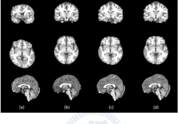
The averaged template image is obtained by averaging all subject images do registration into the template space. The result of the warped image is shown in Fig. 4.5. Fig. 4.5(a) shows the average template image only through the iterative affine registration. Fig. 4.5(b) shows the average template image through the affine and non-rigid registration where the template space was created through the whole iterative affine an non-rigid registration.
4.2 Construction of Brain Templates 45
(a)
(b)
Figure 4.5: The average template through iterative registration. (a) From iterative affine registration. (b) From iterative affine registration and iterative non-rigid registration. The figure shows in coronal view, sagittal view, and horizontal view.
46 Experimental Results
4.2.4
Brain Tissue Template Image
(a)
(b)
Figure 4.6: The different kinds of brain tissue template space and image. (a) The brain-only, whole-brain and brain tissue representative image (template space). (b) The brain-only, whole-brain, and brain tissue average template image. Each subfigure shows in coronal view, horizontal view, and sagittal view (from up to down). From left to right are brain-only, whole-brain, grey matter, white matter, and cerebrospinal fluid images.
4.2 Construction of Brain Templates 47
From the steps of tissue segmentation, we will obtain the the whole-brain, brain-only and brain tissue images. The construction procedure apply on brain-only image to ob-tain the brain-only representative image and averaged template image (Fig. 4.2(b) and Fig. 4.5(b)). We also apply the same transformation on the whole-brain, grey matter, white matter and cerebrospinal fluid images. Fig. 4.6 shows the representative images and averaged template images which are the average warped images in the template space. We named these constructed brain template in Taiwan based on 216 normal subjects were BTT216.
4.2.5
Study Specific Brain Template Image
The construction procedure could be based on any study-specific data to create the customized template space and image. In this study, we construct the template based on different gender groups and age groups.
Gender Template
The male template is constructed by 86 males with age 32.465±11.872 and the female template is constructed by 130 males with age 36.500±13.086. The initial reference image used the constructed template from the whole subject images in the previous study. The procedure of male template construction removes only one outlier image and two outliers from the procedure constructing of female template. The result template image show in Fig. 4.7(a) and 4.7(a).
Age Group Template
Another customized template constructed based on different levels of age. We divided the subject group into six subgroups per 10-age. The constructed template images are shown in Fig. 4.8.
48 Experimental Results
(a)
(b)
Figure 4.7: The customized template based on gender group. (a) Male template image. (b) Female template image. Each subfigure shows in coronal view (upper left), horizontal view (lower left), and sagittal view (upper right).
4.2 Construction of Brain Templates 49
Figure 4.8: The customized template based on age group. Divided the subject group into six subguoups by the age of each subjects. The number of each subject groups is shown in Table 4.1.
50 Experimental Results
4.3
Evaluations of Brain Templates
4.3.1
BTT216 template v.s. ICBM152 template
Intensity standard deviation
In this evaluation method, we compute standard deviation of intensity at voxel coor-dinate in template space for all subject mapping to template space. Fig. 4.9 displays the intensity standard deviation of each voxel from all warped image in different stages of template. The figure also shows the effect from affine to non-rigid and the refinement of iterative registration. The same evaluation method displayed in Fig. 4.10. The variation for each locations of warped image seem larger than BTT216 significantly.
Intensity correlation
Correlation value presents the similarity of two images based on information of image intensity. The value of correlation lies between zero and one. As the correlation value is closer to one, the two images have high similarity. The following figures show the similarity between the template image and the subject images warped into the template space. The comparison template image including the template only constructed from iterative affine registration, the template constructed from whole procedure with iterative affine and non-rigid registration and the well-known ICBM152 template. If the template image is well representing the subject group, the correlation value should be higher. Table 4.3 shows the average correlation value comparing with different template image. In addition to the comparison between BTT216 template and ICBM152 template, we also evaluate the Av-erage191 template which was constructed from 191 normal subject images by Chang [6].