國
立
交
通
大
學
資訊科學與工程研究所
碩
士
論
文
一 個 發 展 普 適 應 用 的 方 法 論
A Methodology to Develop Pervasive Applications
研 究 生:吳尚昱
指導教授:王豐堅 教授
一個發展普適應用的方法論
A Methodology to Develop Pervasive Applications
研 究 生:吳尚昱 Student:Shang-Yu Wu
指導教授:王豐堅 Advisor:Feng-Jian Wang
國 立 交 通 大 學
資 訊 科 學 與 工 程 研 究 所
碩 士 論 文
A ThesisSubmitted to Institute of Computer Science and Engineering College of Computer Science
National Chiao Tung University in partial Fulfillment of the Requirements
for the Degree of Master
in
Computer Science July 2009
Hsinchu, Taiwan, Republic of China
i
一個發展普適應用的方法論
研究生: 吳尚昱 指導教授: 王豐堅 博士國 立 交 通 大 學
資訊科學與工程研究所
碩 士 論 文
摘要
普適計算的進展帶來許多相關普適應用的快速發展,如智慧生活、老人照護 與農業發展等。情境感知的中介軟體技術更進一步提供了改善普適應用服務品 質。本篇論文提出一個適用於廣泛普適應用的模型以及結合工作流程管理系統的 執行框架。藉由此普適應用模型以及執行框架的分層式方法,本論文亦提出一個 發展普適應用方法論。此方法論包含資料模型及發展的工作流程並預期將減少應 用設計者發展普適應用的困難度。最後,一個普適醫療照護應用的例子說明了普 適應用使用工作流程技術的必要性,並且運用提出的方法論來設計此普適醫療照 護應用來證實此方法論的可行性。 關鍵字:普適計算、工作流程管理系統、普適工作流程、普適應用。ii
A Methodology to Develop Pervasive
Applications
Student: Shang-Yu Wu Advisor: Dr. Feng-Jian Wang Institute of Computer Science and Engineering
National Chiao Tung University 1001 Ta Hsueh Road, Hsinchu, Taiwan, ROC
Abstract
Recently, the fast improvements of pervasive computing techniques have been applied to improve pervasive applications, such as smart living, geriatrics care, and agricultural development. For example, the technologies, like context-sensitive middleware, providing the infrastructure for pervasive applications, can help improve service qualities of pervasive applications. This thesis presents a general pervasive application model with an execution framework integrating workflow. By means of the layered-approach of the pervasive application model with execution framework, this thesis also presents an application development methodology, containing the basic data model and development workflow, to reduce the development efforts to design pervasive applications. Finally, a case study of pervasive healthcare application illustrates the necessity to apply the workflow. The case study also validates the feasibility of our development methodology.
Keywords: Pervasive Computing, Workflow Management System (WfMS), Pervasive Workflow, Pervasive Application.
iii
誌謝
本篇論文得以完成首先要感謝的是我的指導教授王豐堅博士,在兩年的期間 的傳道授業解惑讓我在軟體工程技術、工作流程技術以及對於普適計算領域能夠 深入瞭解,並且獲得許多豐富的知識和經驗。另外,也非常感謝口試委員黃冠寰 博士、焦惠津博士及陳俊穎博士的寶貴意見,補足我論文的不足之處。 其次,本篇論文要特別感謝博士班的懷中學長給予許多指導與建議,並且讓 我在遇到許多瓶頸時能夠幫助我突破難關,不管是專業上的建議、研究的技巧和 文章的撰寫,都非常感謝學長不斷的指教,得以順利完成論文。 最後,感謝這段期間家人給予我不虞匱乏的念書環境,並且支持我專心的念 書與研究。除此之外,還有很多好朋友的鼓勵,包含實驗室學長姐及同儕的勉勵, 也特別謝謝口試時給我祈禱打氣的人。由於大家的一路陪伴才得以順利渡過這段 研究生的歲月。iv
Table of Contents
中文摘要... i
英文摘要 Abstract... ii
誌謝... iii
Table of Content... iv
List of Figures... vi
List of Tables...vii
1
Introduction
... 12
Motivation
... 4 2.1 Pervasive Applications ... 42.1.1 A Survey of Pervasive Applications ... 4
2.1.2 Characteristics of Pervasive Applications ... 7
2.2 Development Techniques for Pervasive Systems ... 8
2.3 Pervasive System with Workflow ... 10
2.3.1 Workflow ... 10
2.3.2 The Advantage of Applying Workflow into Pervasive Environment ... 10
2.3.3 Pervasive System with Workflow in u-Healthcare ... 11
3
A Pervasive Application Model and an Execution Framework
... 143.1 The Necessary Components in Pervasive Applications ... 14
3.1.1 Context Model and Context Reasoning ... 17
v
3.1.1.2 RDF Reification ... 21
3.1.1.3 Context Reasoning ... 23
3.1.2 Process Schema and Required Service ... 26
3.1.2.1 Process ... 26
3.1.2.2 Required Service and Service ontology ... 26
3.2 A Framework Supporting the Execution Environment ... 30
3.3 The Communication Mechanism Inside the Execution Framework ... 33
3.4 Summary ... 37
4
A Development Methodology
... 395
Case Study: a Pervasive Health Care System for a Smart Home
... 496
Conclusion and Future Work
... 63vi
List of Figures
Figure 2-1: A Diagram of Pervasive Healthcare and Monitoring Application ... 1
Figure 3-1: An Overview Concept Diagram of General Pervasive Applications ... 15
Figure 3-2: A General Model to Develop Pervasive Applications ... 17
Figure 3-3: The Upper-Level Context Model of Class Hierarchy Diagram ... 19
Figure 3-4: The Two-Level Hierarchical Context Model ... 20
Figure 3-5: An Example of RDF Reification ... 21
Figure 3-6: The RDF/XML Data Serialization Example ... 22
Figure 3-7: The Components of OWL-S [44] ... 27
Figure 3-8: The Service Matching Using OWL-S during Rum Time ... 28
Figure 3-9: An Example of the Specification of a Process and Services ... 29
Figure 3-10: A Framework Supporting the Execution of Pervasive Applications ... 31
Figure 3-11: An Activity Diagram of the Execution Framework ... 34
Figure 3-12: A Collaboration Diagram for the Execution Framework ... 36
Figure 3-13: A Layered-Approach Designing Pervasive Applications ... 38
Figure 4-1: The Basic Data Model at Each Activities of Development Methodology 39 Figure 4-2: A Development Workflow Diagram Designing a Pervasive Application . 40 Figure 4-3: A Workflow of the Domain-Specific Context Model Construction (CMC) ... 42 Figure 4-4: The Workflow of Building Process/Workflow in an Application (BPW) . 44
vii
Figure 4-5: A Workflow of Building Service Descriptions (BS) ... 45
Figure 5-1: The Domain-Specific Context Model in a Smart Home ... 52
Figure 5-2: A Workflow of Pervasive Healthcare Involving the Smart Home, Healthcare Center, and Healthcare Provider ... 54
Figure 5-3: The Bio-Signal Measurement Sub-Process ... 55
Figure 5-4: The Daily Schedule Sub-Process Containing the Scheduling and Regular Serving Process ... 56
Figure 5-5: An Example of Regular Serving Process ... 57
Figure 5-6: A Warning Process Corresponding to MoH Event ... 58
Figure 5-7: An Example of Emergency Handling Process in Healthcare Provider ... 59
Figure 5-8: Two Examples of Required Service Descriptions ... 61
viii
List of Tables
Table 1: The Ontology Reasoning Example ... 24 Table 2: The Defined Rule Reasoning Example ... 26
Chapter 1 Introduction
1993, M. Weiser gave the first ideology about pervasive/ubiquitous computing, and indicated the vision about “computing anywhere” [6]. Weiser stressed that the computation resources would no longer be bound on mainframes, work stations and even personal computers, but can be accessed all around the environments. Recently, many pervasive applications [3][8][9][19][17][20][10][19][35][36] [37][38][39] have been developed and each has its own characteristics. This thesis summarizes these characteristics across several application domains, such as smart living [8][19], pervasive healthcare including geriatrics care [9][20][35][36][37][38][39], agricultural development [10], and so forth. A generic pervasive application is aware of the environment and utilizes its computing resources with better quality. The characteristics of environment-aware/context-aware and utilization of heterogeneous resources/services are the typical factors to complicate the development of pervasive applications.
In order to overcome these difficulties, a general pervasive application model, based on the combination of essential components, maybe applied during the development. In this thesis, we present a model composed of three main components: (1) Context model with reasoning rules, (2) Process/workflow schema, and (3) Required services. The model can describe the scenarios of a pervasive system.
On the other hand, the technologies, like context-sensitive middleware [4][5][29][30], providing the infrastructure for pervasive applications, can help to
improve service qualities of pervasive applications. Based on our pervasive application model, this thesis also presents an execution framework for handling the designed applications. The framework comprises: (1) Context management system (CMS), (2) Workflow management system (WfMS) [12], and (3) Service management system (SMS). The applications among these systems provide pervasive applications an efficient middleware layer to access the pervasive environment. For example, CMS is in charge of acquiring and deducing the sensed context raw data to semantic situations, and then pushing events to WfMS. WfMS executes correspondent handling-processes when receiving events from CMS. The accessing of pervasive environment is through SMS.
Besides, this thesis presents a general methodology, containing a basic data model and a development workflow, to develop pervasive applications based on the pervasive application model and execution framework. In the methodology, the developers first perform the analysis and requirements specification according to our model. Then, based on the requirements specification, the developers construct the details of the elements based on the details of development workflow. Finally, the execution testing/validation are performed. The methodology is described with a data model and workflow in BPMN.
Finally, a case study, the development of a pervasive healthcare application, illustrates the use of the methodology. The workflow in the case indicates the simplification of (i) effective cooperations of participant roles inside the applications, and (ii) effective cooperations among the development roles for the application. In addition, the case study validates the feasibility of our development methodology.
The rest of this thesis is organized as follows. Chapter 2 indicates our motivation: we summarize the characteristics of pervasive applications across different domains, and the existing techniques of pervasive systems. Chapter 3 presents our pervasive application model serving as the application logical layer, and an execution framework serving as middleware to support pervasive environment. Based on Chapter 3, the development methodology containing a data model and a development workflow is presented in Chapter 4. A case study in Chapter 5 indicates how to use the development methodology to design a pervasive healthcare application. Chapter 6 contains the conclusion and future work.
Chapter 2 Motivation
The advanced technologies have introduced the computerization of all the electronic devices and connect them in a network. Heterogeneous services satisfying needs of people thus collaborate to offer a better quality of the daily life. This chapter surveys existing pervasive applications and summarizes their characteristics in Sections 2.1. Besides, the existing pervasive systems or solutions are presented in section 2.3. We will discuss challenges from summarized characteristics of general pervasive applications and the deficiencies of the current related work. In Section 2.4, the advantages of applying workflow into pervasive computing are presented. Our work attempts to provide a more complete architecture combining context model and workflow with required services to develop pervasive applications.
2.1 Pervasive Applications
2.1.1 A Survey of Pervasive Applications
Recent years, more and more pervasive applications are developed, such as applications in smart living [8][19], pervasive healthcare including geriatrics care [9][20][35][36][37][38][39],agricultural development [10], and so forth. This section gives a survey and briefly introduces these applications.
In case of smart living, the sensors or context providers are separated around the living environments to collect contexts. The contexts collected are about the household information and human behaviors such as moving, exercising, and
entertaining around the living environments. Besides, the user’s preference also serves as another source of context. Through pre-defined rule, the pervasive application may automatically react to contexts such as tuning the illumination or purchasing daily commodities through the internet.
Javier Cubo presents a smart living scenario called “Buying and Selling System” [19]. This system enables users to purchase tickets or make reservation of a hotel or a restaurant through handheld devices. The system collects the user’s ID, and service status to generate a workflow to complete the user’s purchasing mission. COCOA [3] also presents a smart living scenario: the e-movie application about anyone, anywhere, and anytime to access a movie. The e-movie application has a workflow performing a sequence of tasks such as display-searching, stream-downloading, and context-capturing. COCOA system claims that a user can browse movie on the presentation units that the environment provides. Through the context-awareness and QoS constraint, COCOA system smartly switches the presentation unit among user’s handheld devices and screens in the environment.
In case of pervasive healthcare, the sensors are attached on the target geriatric/patient and collecting her/his physical status, locations and motions. Whenever emergencies, the pervasive healthcare application enact an emergency aid process to call for help or activate the environment services to provide necessary assistance. After the wearable sensors [35][37][39] collect the physiological information/contexts from patient, the pervasive healthcare application has to transmit these contexts to the healthcare center through the network infrastructure around the target patients’ environment. Once any abnormal status of a patient is identified, the
healthcare center takes a set of reactions. Several researches also focus on the pervasive healthcare monitoring applications [20][35][36][38][39]. We have a further study on Pervasive healthcare (or called ubiquitous care, UbiCare, and u-healthcare) in Section 2.4.3.
In case of agricultural development, the sensors are separated around the environment such as a greenhouse or a farm. The sensors collect the environment parameters such as temperature, humidity, and sun exposure. The data are collected and analyzed by an intelligence system. Through pre-defined rule(s) and/or AI reasoning, the system activates corresponding devices to adjust the environment parameters for the best growth environment.
Other pervasive applications including: the cooperative long distance education model based on pervasive computing [17], the mobile graphic information system (Mobile GIS) [34], and the RFID handheld device of museum guiding system [21]. The characteristics of network long-distance cooperative teaching research based on pervasive environment are summarized as: (1) Concentrate on learners since learners are the anticipants of study activity, and (2) Emphasize the design of the learning environment that uses all kinds of resources to support study. The purpose of mobile GIS is to use geographic data in the field on mobile devices to achieve the environment monitoring. For example, the police officer in campus retrieves the building information and estimates the possible evacuation plans/process when she or he find a fire-alarm situation. The mobile GIS utilizes the GPS positioning techniques to report the exact information around the accident in place of the conventional telephone with human’s voice report. The museum guiding system uses the RFID tag
attached on the exhibition to identify the visitor’s position and transmit information of the exhibition to PDA through the wireless connection.
2.1.2 Characteristics of Pervasive Applications
Based on the above survey, our observation of several characteristics relevant to pervasive applications are as following:
(1) In order to gather the raw data of environment information, a pervasive application utilizes the sensors/context providers, might be distributed or centralized around the environment.
(2) After gathering the raw data of environment information, a pervasive application has its reasoning mechanism to understand the semantic meaning of these raw context data and takes correspondent actions.
(3) A pervasive application might have several kinds of processes combined with a serious of activities such as a scheduling and serving of patient’s daily work, a patient’s physical status monitoring process, and an emergency handling process in the geriatric healthcare application.
(4) For all kinds of process, the handling process for context change in pervasive applications might be trivial or complex.
(5) The core feature of pervasive applications is to utilize the ubiquitous services around the environment. Unfortunately, these services contained by devices or hardware resources might have heterogeneous interface and might be unknown in advance.
These summarized characteristics above are the crucial concerned to develop a pervasive application. This work attempts to generalize all the factors affecting the development of pervasive applications. The next section discusses the existing development techniques of pervasive systems.
2.2 Development Techniques for Pervasive Systems
CoCA [4] is a platform combing a pervasive environment, GCoM modeling (a context model [16]), and CoCA services (context-aware services) for execution of pervasive applications. CoCA uses a Rule-Constraint-Action (RCA) engine to response the environment change and to enact corresponding service. The scenario in CoCA [4] is to assist people’s devices in the campus to intelligently react to the change of environment. For example, the CoCA platform can turn a student’s cell phone into silent mode when she/he enters into the library. CoCA platform gives a well-defined context model and each individual device/service is able to react to the context. However, CoCA is lack of the ability to deal with the more complex process that is involved interaction with environment and compose several services to achieve the goal of an application.
COCOA [3] is a solution for QoS-aware COversation-based service Composition in pervAsive computing environments. COCOA is comprised of three parts: (1) COCOA-L (Language), (2) COCOA-SD (Service Discovery), and (3) COCOA-CI (Conversation Integration). COCOA-L is built upon semantic web services, particularly OWL-S. COCOA-SD performs the dynamic realization of user tasks from networked services available in the pervasive computing through the description of
COCOA-L. Finally, COCOA-CI rapidly interleaves services into pre-defined workflows. The qualities of services (QOS) are verified upon control and data dependencies, and the services are quickly reconfigured when the user’s contexts change. However, COCOA is lack of a context model to perceive and response the change of environment.
In [11], Ranganathan used workflow engine as a coordinator to integrate web services into a pervasive environments. In [1], F. Montagut provides a pervasive workflow architecture in which a workflow is under distributed control over the participated devices and allows dynamic task assignment. However, the pervasive workflow architecture is also lack of context-awareness mechanism to response the change of environment.
CoBrA-Ont [14] develops architecture to enable distributed agents (Context Brokers) to control the access of their personal information in a context-aware environment. Through a semantic web technology called CoBrA Ontology, the context brokers cooperate and exchange the information around them to achieve the purpose of context-awareness. CONON [15], an ontology approach for reasoning and representation of contexts, is based on the treatment of high-level implicit contexts that are derived from low-level explicit contexts (raw data from sensors/context providers). The above two research highlight the context-awareness in pervasive environments; however, how to handle the complex processes in a pervasive application is not discussed.
2.3 Pervasive System with Workflow
2.3.1 Workflow
Workflow Management Coalition (WFMC) define a workflow as: “The
automation of a business process, in whole or part, during which documents, information or tasks are passed from one participant to another for action, according to a set of procedural rules [12].” In addition, WFMC also defines the Workflow
Management System (WfMS) as: “A System that defines, creates and manages the
execution of workflows through the use of software, running on one or more workflow engines, which is able to interpret the process definition, interact with workflow participant and, where required, invoke the use of IT tools and application [12].”
The benefits of Workflow are summarized as:
(1) The management of resources allows dynamic task assignment.
(2) Workflow allows human actor to perform actions that push forward the state of process.
(3) The delegation of a task to a role increases the responsibility
(4) Workflow complies with required services and regulatory requisites, hence accomplishing results by implementing well-made processes.
2.3.2 The Advantage of Applying Workflow into Pervasive Environment
Most pervasive applications are involved of complex processes divided into a number of smaller tasks. After interaction with the environment, pervasive
applications are aware of the services the environment supports. Hence, using workflow can successfully describe the tasks in advance, and allow integrating/composing the available service during run time. In addition, the benefits of workflow in Section 2.4.1 also fit the applying workflow into pervasive environment. These advantages are discussed as:
(1) Workflow enforces the order constraint and specifies the transition rules among tasks. Hence, the application developers can plan workflows structuring the interaction between user and environment to integrate pervasive services during run time.
(2) By means of service composition techniques [55][56][57], the workflow structure can achieve the higher quality of service (QoS).
(3) The delegation of a task to a role increases the responsibility. For example, the pervasive healthcare application needs to administrate the duty of healthcare staffs.
(4) The execution of workflow on workflow engines is able to handle exceptions/fault while the pervasive environment might be full of uncertainties.
2.3.3 Pervasive System with Workflow in u-Healthcare
Figure 2-1: A Diagram of Pervasive Healthcare and Monitoring Application
The aging population is a growing problem throughout the global. The elderly people, suffering from the chronic diseases, require the medication and the regularly clinic visiting. Hence, an efficient pervasive healthcare and monitoring application is becoming crucial in recent years. However, an application of pervasive healthcare is involved of many challenges such as: (1) the context-aware monitoring of the patient, (2) The handling process when an emergency happens. The above Figure 2-1 illustrates the pervasive healthcare application.
One discussed scenario is about an aged patient suffering from hypertension is now rest at home. Wearable sensors equipped with the patient collects his signs of life such as heart beating, blood pressure etc. Video sensors are deployed in living room to capture his motions. The patient’s handheld monitors the information collecting by sensors. The handheld warns the care center through telephone when any emergency. All the devices are connected by wireless network.
Suddenly, the patient feels discomfort due to headache. The wearable sensors detects the blood pressure of this patient is Diastolic = 155 mm hg & Systolic = 99mm hg. The video sensors capture the patient’s posture is falling. The handheld identifies the patient is on the morbidity of hypertension. As a consequence, a warning message with vibration of handheld is triggered, and intermediately transmits the physiological data from wearable sensors to care center. Through professional judgment, the care canter confirms the patient is under an emergency status. Hence, a sequence of activities is performed: (1) Inform the physician and transmit relevant medical history, (2) Inform care provider to send ambulance, and (3) Inform Hospital to prepare correspondent handling process…
In this scenario, pervasive healthcare including geriatrics care has highlighted the need of applying the workflow techniques into pervasive systems. Workflow technique is able to represent the pervasive healthcare monitoring process involving a sequence of activities associated with many participants. In Chapter 4, we will explain how to design a pervasive healthcare application based on our system architecture.
Chapter 3 A Pervasive Application Model and an Execution
Framework
On account of the characteristics of pervasive computing discussed in Chapter 2, there are some challenges for the developers to build the pervasive applications. For example, a better expressive model reduces the efforts of recognition for the environment; an efficient approach describes the complex process/workflows performing a sequence of tasks, and a mechanism acquires/accesses ubiquitous services that the surrounding provides during run time. In order to reduce these difficulties, our observation indicates three fundamental components regarding to developing pervasive applications. A pervasive application model with necessary components and their detailed formats is presented in Section 3.1. And to separate the design issues from run time, a framework supporting the execution environment is proposed in Section 3.2. An activity diagram and collaboration diagram illustrating the operation of the execution framework is presented in Section 3.3.
3.1 The Necessary Components in Pervasive Applications
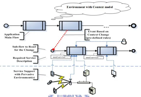
Figure 3-1 illustrates a conceptual overview of general pervasive applications based on the discussion in Chapter 2. Context-model is used to capture and perceive the environment. The application flow indicates the relationship among tasks during run time. The sub-flow(s) handles the context-changes in the surrounding. The required service description designates the necessary services of an application. In the
lower-part of Figure 3-1, services, distributed over a specific environment, dynamically support the executing tasks.
Figure 3-1: An Overview Concept Diagram of General Pervasive Applications.
According to the discussion in Chapter 2, we can conclude at least three necessary components in pervasive applications:
1. Context Model and Reasoning rules. Since the pervasive environment alters all the time, it is essential to use a context model to capture the change. Moreover, the pre-defined rules are applied for reasoning the status of context entities. By means of the context model and context reasoning, the pervasive system can understand the environment and properly react to the changes. Thus, the context model with related reasoning rules is the first
necessary component to develop a pervasive application. Section 3.1.1 gives a detailed explanation of our context model approach.
2. Process Schema. In the design time, the developers specifiy the tasks, their execution order, and other control structures (e.g. if-then-else, loop, sequence, and so on) in an application. The above relationship among tasks is regarded as business processes (or processes) in an application. During run time, the pervasive system instantiates correspondent handling processes based on the current status of environment. Hence, the process schema is the second necessary component to develop a pervasive application. Section 3.1.2 gives a detailed explanation of our process schema approach.
3. Required Services. The service description details the interaction between a task and its required services, whereas the above process schema indicates the execution logic among all tasks. However, the developers might not anticipate all run-time available services, and therefore the developers describe required services in an abstraction manner. A platform-independent service description, thus, is the third necessary component to develop a pervasive application. Section 3.1.3 gives a detailed explanation of our required service description approach.
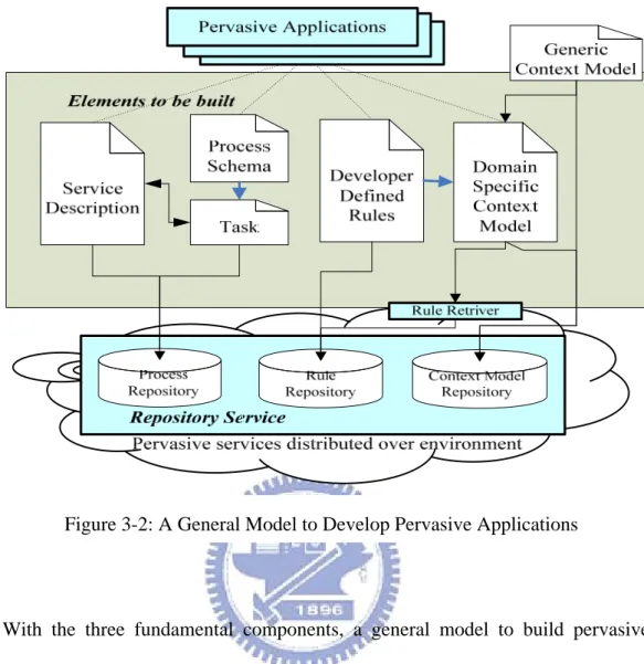
Figure 3-2: A General Model to Develop Pervasive Applications
With the three fundamental components, a general model to build pervasive applications is proposed as Figure 3-2. Based on the designing application, the developers build elements in the dashed rectangle in Figure 3-2 to construct pervasive applications among different domains.
3.1.1 Context Model and Context Reasoning
Two widely-accepted definitions of context, and context-aware systems given by A.K. Dey states [28]:
“Context is any information that can be used to characterize the situation of an entity.
An entity is a person, place or object that is considered relevant to the interaction
between a user and an application, including the user and the application themselves.”
“The systems that use context to provide relevant information and/or services to the
user, where relevancy depends on user tasks”
Pervasive system is a kind of context-aware systems; therefore, a context model is utilized to recognize and capture the context that an application needs. This section explains our context model approach and how the developers design their domain-specific context models.
3.1.1.1 The Two-Level Hierarchical Approach
Our context model is a two-level hierarchical approach using ontology. The upper-level, representing for the generic context model, depicts the universal concepts throughout all pervasive application domains. The lower-level, representing the domain-specific context model, appropriately describes the features within an application domain. The upper-level context ontology is fixed and shared once defined, while the lower-level context ontologies are diverse along with domains.
The hierarchy of ontology classes categorizes the terms and specifies relationships associated with the context entities in the environment. The hierarchical structure emphasizes the machine-understandability of context information, supporting for the abstraction programming of capturing the environment in the development of pervasive applications.
Through Dey’s definition and the observation of pervasive application in Chapter 2, we conclude a skeleton of context model:
1. Basic Entities:
• Locations (indoor space or outdoor space) • Individuals (persons or non-persons).
• Activity (scheduled activity or a deduced situation) • Service (context providers, devices, network )
2. Properties/Relationships among the Above Entities:
• Individual, Activity, and Service must be located in a Location. • In some location, Individual is engaged in some Activity
utilizing Services that environment supports.
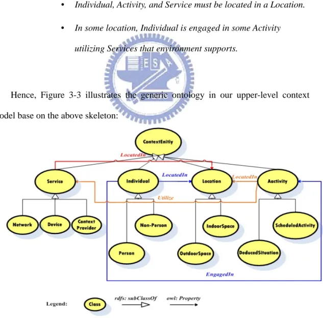
Hence, Figure 3-3 illustrates the generic ontology in our upper-level context model base on the above skeleton:
Figure 3-3: The Upper-Level Context Model of Class Hierarchy Diagram
With the above generic ontology serving as a generic context model, it provides the application developers or domain experts a coarse-grained backbone to design fine-grained context features suited for the application domain. The partition of different domains assists the application developers reduce the scale of context knowledge, and allow to reuse the domain-specific context models defined by third parties. In addition, by means of the context management system (CMS) in the framework (mentioned in Section 3.5), these domain-specific ontologies can be dynamically applied when the pervasive surrounding is altering.
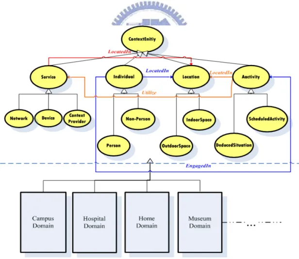
Figure 3-4 shows that the ontologies of different domains derived from the generic context model.
Figure 3-4: The Two-Level Hierarchical Context Model
3.1.1.2 RDF Reification
The OWL ontology can be mapped into RDF graph that is a collection of RDF triples. Each RDF triple is a statement containing three parts: (1) subject, (2) object, and (3) predicate. The statement can be described and recorded by RDF reification using the RDF/XML syntax specification. According to W3C, RDF reification vocabulary consists of the type rdf:statement, and the properties rdf:subject,
rdf:predicate, and rdf:object. The following example explains the RDF reification.
Figure 3-5: An Example of RDF Reification
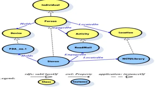
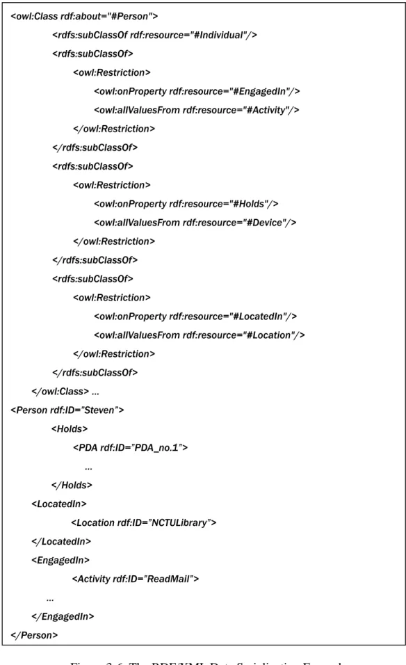
Figure 3-5 shows the abridged part of our upper-level context model with respect to the context entity of “Person”, and a real instance in some application called “Steven”. Person is the subclass of Context Entity. Person holds some Device. Person is engaged in some Activity. Person is located in some Location. Figure 3-6 shows the RDF/XML data serialization related to the context entity of a person.
<owl:Class rdf:about="#Person"> <rdfs:subClassOf rdf:resource="#Individual"/> <rdfs:subClassOf> <owl:Restriction> <owl:onProperty rdf:resource="#EngagedIn"/> <owl:allValuesFrom rdf:resource="#Activity"/> </owl:Restriction> </rdfs:subClassOf> <rdfs:subClassOf> <owl:Restriction> <owl:onProperty rdf:resource="#Holds"/> <owl:allValuesFrom rdf:resource="#Device"/> </owl:Restriction> </rdfs:subClassOf> <rdfs:subClassOf> <owl:Restriction> <owl:onProperty rdf:resource="#LocatedIn"/> <owl:allValuesFrom rdf:resource="#Location"/> </owl:Restriction> </rdfs:subClassOf> </owl:Class> … <Person rdf:ID=”Steven”> <Holds> <PDA rdf:ID=”PDA_no.1”> … </Holds> <LocatedIn> <Location rdf:ID=”NCTULibrary”> </LocatedIn> <EngagedIn> <Activity rdf:ID=”ReadMail”> … </EngagedIn> </Person>
Figure 3-6: The RDF/XML Data Serialization Example
3.1.1.3 Context Reasoning
Section 3.1.1.3.1 and Section 3.1.1.3.2 describes how context model captures and perceives the pervasive environment. The direct acquisition of context from the environment contains the raw data that only represents the low-level information (such as location, sound, video pictures and so on.) In order to identify the high level status of a context entity, a mechanism called context-reasoning is required to extract more useful information from these raw data of context.
The context-reasoning performs two major categories of tasks that are discussed in the following: (1) Ontology-reasoning employs description logic (2) Developer-defined rule reasoning utilizes first-order logic.
(1) Ontology Reasoning
Web Ontology Language (OWL) is W3C recommendation to makes use of web standards to represents information with RDF/XML schema. OWL is based on Description logic (DL) that specifies the hierarchy of terminologies by means of a restricted set of first-order formulas. Hence, the equivalence of OWL and Description logic (DL) supports the use of existing DL business segment for class consistency, instance checking, and concept satisfaction.
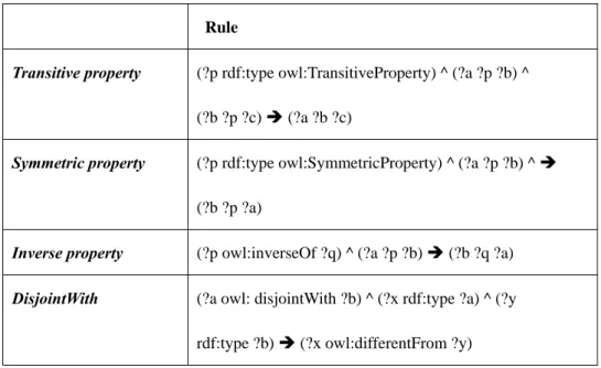
Table 1 shows the partial form of ontology reasoning rules based on description logic.
Rule
Transitive property (?p rdf:type owl:TransitiveProperty) ^ (?a ?p ?b) ^
(?b ?p ?c) Î (?a ?b ?c)
Symmetric property (?p rdf:type owl:SymmetricProperty) ^ (?a ?p ?b) ^ Î
(?b ?p ?a)
Inverse property (?p owl:inverseOf ?q) ^ (?a ?p ?b) Î (?b ?q ?a)
DisjointWith (?a owl: disjointWith ?b) ^ (?x rdf:type ?a) ^ (?y
rdf:type ?b) Î (?x owl:differentFrom ?y) Table 1: The Ontology Reasoning Example
An example illustrates the ontology reasoning. If Steven’s location sensed is in the NCTU library, then the owl description is shown as:
<Person rdf:ID=”Steven”> … <LocatedIn>
<Location rdf:ID=”NCTULibrary”> </LocatedIn> …
By applying the defined context model of owl description about NCTU library and the transitive property as:
<Location rdf:ID= “NCTU Library”> <LocatedIn>
<Location rdf:ID=”NCTU Campus”> </LocatedIn> …
<owl:ObjectProperty rdf:ID = “LocatedIn” >
<rdf:type=”…<URI>…TransitiveProperty”> </owl:ObjectProperty>
Thus, the ontology reasoning gets the result:
<Person rdf:ID=”Steven”> …
<LocatedIn>
<Location rdf:ID=”NCTU Campus”> </LocatedIn> …
(2) Developer-Defined Rule Reasoning
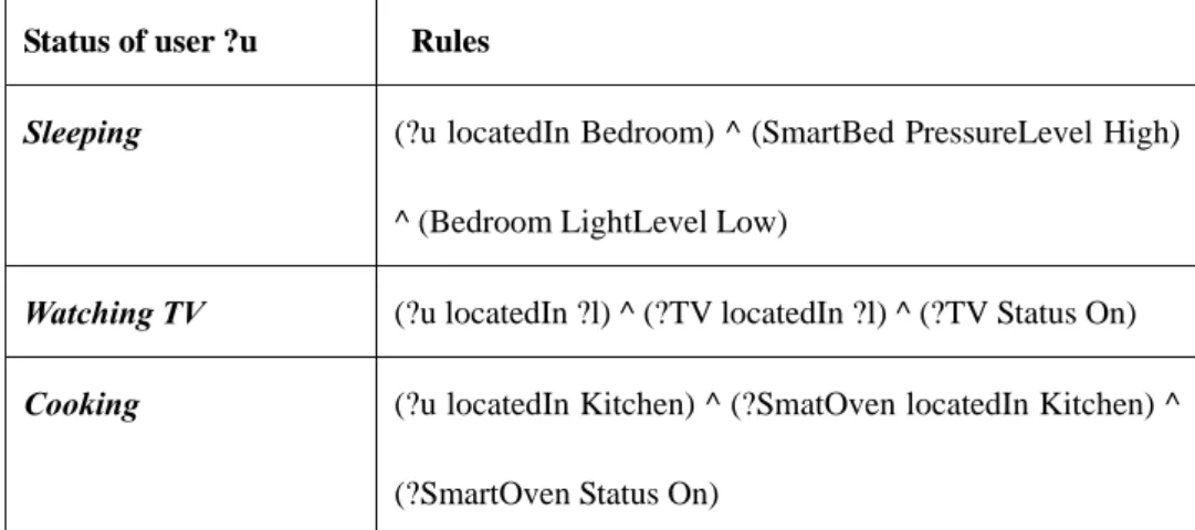
Developer-Defined Rule offers the more flexible approach for the designers to perform context-reasoning suitable for their applications. In the design phase of an application, the developers can define their reasoning rules in conformity with the format of first-order logic. During the running phase, exploiting these developer-defined rules, the CMS deduces the high-level status contexts from the raw data of contexts gathered by the sensors/context providers. The following examples illustrate the reasoning by developer-defined rules:
Status of user ?u Rules
Sleeping (?u locatedIn Bedroom) ^ (SmartBed PressureLevel High)
^ (Bedroom LightLevel Low)
Watching TV (?u locatedIn ?l) ^ (?TV locatedIn ?l) ^ (?TV Status On)
Cooking (?u locatedIn Kitchen) ^ (?SmatOven locatedIn Kitchen) ^
(?SmartOven Status On)
Table 2: The Defined Rule Reasoning Example
3.1.2 Process Schema and Required Service
3.1.2.1 Process
The process specification is used to navigate tasks that make up an application. The execution of a process during run time is viewed as a workflow. The operational language we use to express the process is by BPMN [43]. The structured activities defined by BPMN, including sequence, flow, switch, while, and so on, can represent the relationship among tasks in the design time of an application.
The developers cannot anticipate all the run-time available services for the tasks in an application. Hence, the process specification needs the extra description to record the required services. The adopted method is by adding the semantic annotations associated to a process to mark up the used service during run time. The next section illustrates how to describe the required services and gives an example.
3.1.2.2 Required Service and Service ontology
Similar to context model, the service description needs a semantic but computer-interpretable language for the pervasive systems to control and administrate services. The service ontology, used to declare and describe the services, consists of a collection of classes and properties to provide the appropriate representation framework.
OWL-S [44], a web service ontology specified in OWL, is composed of three parts: the service profile, the service model, and the service grounding (see Figure 3-7 [44]). The service profile portrays the high level description of a service and its provider. The service model details the service behavior as step-by-step processes (atomic process, simple process, or composite process) under a set of control construct (e.g. Sequence, Split, Choice, If-Then-Else, Repeat-While and so on…). The service
grounding specifies the necessary information (e.g. communication protocol, message
format, port number etc…) to access a service. Note that the service profile and the
service model deal with the abstraction representation of a service, while service grounding copes with the concrete level of specification of a service.
Figure 3-7: The Components of OWL-S [44]
The pervasive-service providers are suggested to use OWL-S to specify their advertised services. Additionally, user tasks in a pervasive application process also
specify the required service description in the format of OWL-S. The following Figure 3-8 illustrates the relationship between advertised services from service providers and requested services by user tasks. There are serveral OWL-S systems (such as [45], [46]) performing service discovery and matching. The further study of the semantic service by OWL-S is out scope of our study.
Figure 3-8: The Service Matching Using OWL-S during Rum Time
In Figure 3-8, the service management system (SMS) is designed to administrate the services that service providers advertize and the processes require during run time. The service management system is one sub-system of our framework supporting the execution environment of pervasive applications (shown in Section 3.4).
The following example in Figure 3-9 shows how the developers specify a process and its required service descriptions. The upper-part of Figure 3-9 is an example of process. In this thesis, we use BPMN to model the processes in an application, and BPMN can translate into BPEL for execution. In the lower-part of , Process.bpel denotes the correspondent BPEL representation, and
RequiredService.xml is associated to the process in order to mark up the used services
during run time. Figure 3-9
Figure 3-9: An Example of the Specification of a Process and Services
Since both the required service within a process and pervasive services in any kinds of environments conform to the format of OWL-S, the SMS can perform the service discovery, and service matching when a process is running.
3.2 A Framework supporting the execution environment
In the following Figure 3-10, a framework is designed to support the execution environment for pervasive applications. Hence, the designers can concentrate on constructing the required elements of an application. The goal of the framework assists the developers to focus on building the fundamental components in Section 3.1.
The framework consists of three major sub-systems corresponding to the three requirements in Section 3.1: (1) Context management system (CMS), (2) Workflow management system (WMS), and (3) Service management system (SMS).
In order to adapt the diverse environments, our framework adopts the concept of service-oriented architecture (SOA). The framework only preserves the necessary components. Taking the function of data-storage for example, it is often resource hungry but widely used by most components. As a result, our framework encapsulates the function of data-storage into the repository service that is provided according to environments. Since CMS and WMS require accessing the context model data, rules and process patterns frequently, the decoupling of data storage into service also minimizes the loading of the framework. Other encapsulated services, such as computation resources, reasoning modules, and devices, also follow the principle of
SOA and the other components in the framework can easily access these wrapped services provided from the third parties in the various pervasive surroundings.
s in our framework:
(1) Context Manageme
Figure 3-10: A Framework Supporting the Execution of Pervasive Applications
The following explains the three sub-system
nt System (CMS):
The CMS comprises three major components: (1) Context capturer, (2)
Context manager, and (3) Context repository. The context capturer captures
the raw data of environment context and stores them into context repository. The context manager is composed of a context handler and an event handler, thus processing the input context data. The context handler scratches context data from the context repository and utilizes domain-specific context model and developer-defined rules (stored in repository service) to reason the high-level status of context entities. The reasoning result represents the current situation in the environment. Once the reasoned situation matches some event, the event handler informs the workflow
(2) Wor
nts, performing tasks, and monitoring the execution of processes. Moreover, WfMS acquires available services by means of management system.
kflow Management System (WfMS):
After the CMS informs WfMs, the WfMS coordinates all participants within the workflow to perform a sequence of tasks. The process definition (stored in the process repository) provides the basic schema to execute the tasks required in the pervasive applications. The application developer defines the executing process patterns, whereas, WfMS is in charge of coordinating participa
requesting the SMS.
(3) Service Management System (SMS):
In conformity with the principle of SOA, the designed framework decomposes large elements into a set of wrapped services that may be provided by the third-party. Hence, the SMS has to furnish a mechanism to register and index these services. Besides, the pervasive service providers can also advertise their service by means of the SMS. Furthermore, The CMS and the WMS access the pervasive environment through the SMS so that they could easily locate and access the services. However, sometimes the requests from WfMS or CMS may not be achieved by a single service. The Service Proxy and Coordinator would comp
enting how to enable a BPEL workflow to dynamically invoke the service in the pervasive environment. The
the run-time rvices within a BPEL workflow.
3.3 T
ram with relevant to the execution framework presented in Chapter 3. Since three elements built must be running upon
ose several services into one temporary service composition to provide proper facilities.
The run time available services for the tasks of a workflow register their OWL-S service descriptions to the SMS. After the matching of the task and pervasive services, the SMS can specify the partnerLink of the selected service into the BPEL representation of a workflow and establish the communication channel. There are some systems [1],[47] pres
SMS in our framework can also use these systems to achieve invocation of se
he Communication Mechanism inside the Execution
Framework
Figure 5-3 illustrates the activity diag
the execution framework, we use the activity diagram of execution framework to interpret the details of invocation and flows.
When a pervasive application starts, it activates the primary process and context gathering processes. The primary process is executing on the WfMS while the context gathering process is performing a sequence of tasks on CMS. CMS periodically senses the environment contexts, applies them to the context model, and reasons the semantic meaning behind them. On account of decoupling the databases into the
Figure 3-11: An Activity Diagram of the Execution Framework
repository service on SMS, CMS must request the SMS to acquire the static data of domain-specific context model and pre-defined rules. Although the context gathering rocesses and primary process are running concurrently, CMS interrupts WfMS (push
nce, the concurrent execution of processes can be xpressed when the developer models all the processes with an application. Furth
rvasive application requires considerable computing power, the developer can install a cluster of computers or any other forms of grid computing. Pervasive service support is a collection of other pervasive services around the deployed environment.
p
-event delivery) if any deduced situations are confirmed. As a consequence, WfMS activates the handling sub-processes and requests SMS the required services.
Both the push-event delivery from the environment context to handling sub-processes and the pull-context about service status are modeled by BPMN notation in the design phrase. He
e
erm es can examine whether there are conflict in the execution of multiple processes.
In Figure 5-3, there are some rounded rectangles called: repository service support, reasoning service support, computation resource support and pervasive service support within SMS. Repository service support provides the storage for the data of domain-context model, developer-defined rules, process patterns etc. Reasoning service support provides the context reasoning support. For example, the image analysis from the video sensors can be wrapped into a service. Computation resource support provides a connection between grid computing and pervasive computing. That is, once the execution of a pe
ore, some existing research
Figure 3-12: A Collaboration Diagram for the Execution Framework
A collaboration diagram shown in illustrates the inter-cooperation among CMS, WfMS, and SMS. Our system keeps sensing the environment context c. CMS performs getSemantic(c) through context reasoning and push events to WfMS if necessary. Once receiving events, WfMs switches to the correspondent handling process. According to the required service descriptions, WfMS requests SMS and then SMS pull the services’ status/context from CMS. After acquiring the services’ status, SMS match available services by required service description and select one of them through pre-defined policy. Finally, SMS returns the selected service to WfMS.
Figure 5-4
3.4 Summary
In this chapter, an application model involving three fundamental components and their details are presented for the developers to design their applications. Additionally, a framework supporting the execution environment is also presented. The decoupling of resource-consuming parts into wrapped services not only minimizes the number of elements needed to be maintained, but enables the
deployment of our framework into the various pervasive environments. On account of conforming to the principle of SOA, the framework also enhances the convenient accessing and reusability of services.
Figure 3-13 illustrates the layered-approach to design applications. In the
application logic layer, the developers build the elements in our pervasive application model. In the Middleware, the developers deploy the system according to our
execution framework. Through the cooperation of three sub-systems in the execution framework, the designed application can access the services in the pervasive
environment. Besides, this layered-approach assists developers to focus on designing their applications. And, the developer can adopt their designed application to
distinguished environments by means of deploying the middleware layer upon the applied environments. The advantage of the layered-approach involving: (1) Reduce the difficulties of pervasive application design. (2) Minimize the elements to be built but fit the general pervasive applications. (3) Adapt pervasive applications to different environments.
Figure 3-13: A Layered-Approach Designing Pervasive Applications
Chapter 4 A Development Methodology
This chapter introduces a development methodology of pervasive applications based on the application model and execution framework in Chapter 3. Following the specification principles of context model, process schema, and service description, the developers can design their pervasive applications. and
illustrate how to develop pervasive applications from two distinct viewpoints.
indicates the necessary data items in the development methodology, whereas shows the development workflow for such applications in BPMN.
Figure 4-1
Figure 4-1
Figure 4-2
Figure 4-2
Figure 4-1: The Basic Data Model at Each Activities of Development Methodology. 39
Figure 4-2: A Development Workflow Diagram Designing a Pervasive Application.
In Figure 4-2, the application developers are categorized into three main roles: application analyzer, element developer, and application deployer. By combining both viewpoints in Figure 4-1 and Figure 4-2, we present a development methodology with workflow for pervasive applications as below:
(1) Application Analysis and Requirement Specifications by Analyzers:
Through the investigations or negotiations with customers, this stage analyzes the following data and questions completely:
I. The goal of the application with necessary service processes.
II. The participants/organizations in this application. III. Used pervasive services in this application.
IV. The context entities with their attributes and relationships for the applied environment.
In this stage, the above data are closely-related to the rest of development methodology. Items I and II are used for the process construction in the Step (2-2). Item III assists the developers to give universal service descriptions in the Step (2-3) and build the context information of service part in the domain-specific context model. Item IV helps to construct the knowledge about the deployed environment, and is derived from the generic context model presented in Chapter 3. In addition, the domain analysis [40][41][42] helps the developers define the common and variable parts in Step (2-1).
(2) Constructing Elements by Element Developers:
This stage develops the data items inside each of three elements shown in . The development workflow in contains: (2-1) Building the domain-specific context model with reasoning rules, (2-2) Building processes/workflows, and (2-3) Building service descriptions, as below:
Figure 4-1 Figure 4-2
(2-1) Building Domain-Specific Context Model with Reasoning Rules:
Figure 4-3: A Workflow of the Domain-Specific Context Model Construction (CMC)
Figure 4-3 illustrates the workflow of domain-specific context model
construction: Firstly, the element builders decide whether to reuse the
existing domain-specific context model. If yes, the element builders search suitable/applicable models. Otherwise, they build their own model with the following steps:
Step 1: Derive basic entities, their context attributes and relationships. This step uses Item IV in Stage (1) to construct the knowledge about the applied environment.
Step 2: Define deduced situation classes with reasoning rules. The semantic meanings deduced from the raw context data are
defined as the deduced situation classes in the domain-specific context model. In order to achieve the application goal, a deduced situation represents an event that a designed application is required to handle. The developer extracts the deduced situations from Item I in Stage (1).
Next, the element builders check the consistency and completeness of the first context model developed, and tunes it up if necessary. The context-model checking involves the ontology checking [49][50][51][52][53]. The result of model checking may contain a fatal error. For example, a context entity derived in (IV) in Stage (1) may not be well compiled in the model. If such an error occurs, a re-modeling work is adopted, so does the checking. The followings indicate the checking searches the following ontology errors:
(1) Trivial errors: Syntax errors or type errors.
(2) Logical errors (consistency in ontology): Disjoint contradiction, complementary contradiction, and others like Satisfiability, Subsumption, Equivalence, etc.
(3) Redundant rules: Rules that infer the same situation can be merged.
The checking-and-tuning is a loop until the errors in the designed domain-specific context model are solved. There are several tools [49][54] which can be applied to perform the checking/tuning. Then, the deduced situation classes are transmitted to the process builders to perform (2-2).
Besides, the service entities defined in the domain-specific context model might be performed concurrently; however, its developing activity cannot start until (2-3) completes. In , we use a massage event to indicate the wait. After getting the services, the corresponding (service) part in the model is constructed and (2-1) completes.
Figure 4-3
(2-2) Building Process/Workflow:
In this sub-stage, the element developers extract the processes/workflows from the Items I and II. There are at least two types of processes needed to be constructed:
Figure 4-4: The Workflow of Building Process/Workflow in an Application (BPW)
i. The processes associated with participants/organizations: This process is globally in charge of the cooperation among participants/organizations based on control logic and transitions.
ii. The event-handling process: This process deals with the events delivered from context management system. The events correspond to the deduced situation classes in Step 2 in (2-1), Hence, the developers identify events and specify the event-handling processes.
The built processes in the above type ii are relevant to the context-changing and the correspondent reaction, while the built processes in the type i are not.
Figure 4-4 illustrates the workflow of building process/workflow. In the beginning, it contains two sub-flows. In the bottom flow, the element builders construct processes of type i that are associated with participants/organizations. In the top flow, a message event is designed to represent the wait: the event-handling process of type ii relies on the context entities and deduced situation classes specified in (2-1); i.e., the element builders cannot start to construct this type of processes until the specification of context entities completes.
If a process of other types is needed, it can be constructed in the last developing activity after a concurrent join of the above two sub-flows in . Finally, the process builders inform the service builders when the application process/workflow building is complete.
Figure 4-4
(2-3) Building Services Descriptions
Figure 4-5 illustrates the workflow for building service descriptions. In the beginning, it contains two sub-flows. The top flow waits until the element builders completes the specification of processes/workflows in (2-2) and pass them in. After passing the built processes/workflows in, the element builders attach the required service descriptions to the tasks of each built process/workflow. In the bottom flow, the element builders specify the service descriptions to used pervasive services in the applied environment. Hence, a developing activity transmits services described previously and throws a message event to notify the waiting of CMC in Figure 4-3. The specification of service descriptions in the above two sub-flows conform to OWL-S format in Chapter 3. After a concurrent join of the above two sub-flows in Figure 4-4, the construction of (2-3) is completed.
Figure 4-5: A Workflow of Building Service Descriptions (BS)
After the construction of the service parts of domain-specific context model in (2-1) is completed, all the elements in a pervasive application are built and a pair of throwing–catching events indicates to go to the next development stage.
(3) Deploying Execution Framework Based on Target Environments By Deployers:
Firstly, to instantiate the designed pervasive application system, the developers deploy CMS, WfMS, and SMS in the application environment according to our framework as centralized or distributed. For example, a smart home can adopt the centralized deployment approach, while a hospital or a shopping mall is suggested to use the distributed deployment approach.
Next, the developers may request the service providers to furnish used pervasive servicers in all derived-processes if the applied environment lacks of them. For example, the used pervasive services in a pervasive healthcare application are wearable sensors, video sensors, handhelds etc. in a smart home.
Finally, the applications developers put the built elements into three repositories in the execution framework: (1) the context-model elements including the generic and domain-specific context models are put into the context repository, (2) The reasoning rules are put into the rule repository, and (3) the process/workflow elements with the required service descriptions are put into the process repository.
(4) Execution and Feedback:
This stage performs the testing of the designed pervasive application. There are several challenges associated with the testing of pervasive applications:
(1) Testing data rely on the sensor data. In [58], T.H.Tse et al. indicates that the simulated and real senor data are both crucial to examine a pervasive application.
(2) The pervasive applications are not adequate to perform unit testing since In [59], M. Bylund and F. Espinoza indicate the behavior of context-aware applications is determined by rules that may be independent from the codes.
In terms of the above challenges, so far there are no efficient solutions to solve these problems. Hence, we present a simple testing strategy by means of the workflow integration testing currently. According to the requirement of the designed application, the testers design the testing sets of context information and examine their execution results and behaviors. The application running with test sets may indicate: (a) Deadlock, happening if more than two workflows access the same services. (b) Unreachable states in the defined process.
Once the testing results yields the unsatisfactory behavior, these test results are feed backed to element builders to fine-tune the built elements, and the whole work is started as the next turn. The details of testing activity will be studied further in our future work.
Chapter 5 Case Study: A Pervasive Healthcare System for a Smart
Home
This chapter applies our methodology to the example described in Section 2.4.3 to indicate its usability. Obviously, a smart home is usually supported by one or more healthcare center/providers for emergency handling. Each step in the development is described in details as follows:
(1) Analysis and Requirement Specification :
I. Several service processes to achieve the goal of this application:
A. Daily scheduling process: Arrange a target patient’ daily schedule according to her/his medical history and physician’s instruction.
B. Regular serving process: Daily serves according to the scheduling from A.
C. Context monitoring process:
(1) Bio-signal measurement process: Gather a patient’s bio-signal data like the blood pressure repeatedly.
(2) Posture-capturing processes: Capture the patient’s motion/posture repeatedly.
D. Emergency handling: If the abnormal blood pressure or abnormal motion/posture is detected from C, the emergencies are identified to request the healthcare center to provide aid-support.
II. Participated organizations:
The organizations in this application are categorized into: (1) Smart Home (2) Healthcare center, and (3) Healthcare provider including hospitals, where the latter two are third-parties for supporting. Each target patient is located at a smart home. And, the environment information in a smart home is specified as context entities in a home-specific context model. The details of context entities in a smart home are analyzed in IV.
III. Used services in a smart home:
The context providers include wearable sensors and video sensors. A handheld is in charges of processing the context data and displays the jobs according to the patient’s daily schedule. PCs have a capability to perform a video conference with staffs in the healthcare center or physicians in hospitals. These devices should be connected through wireless network.
IV. The context entities with their attributes and relationship in a smart home:
The following analyzes the context entities in a smart home based on the generic context model presented in Chapter 3.
The subclasses of person in a smart home are patient, physician, and
nurse. Physicians and nurses can contact with the target patient through
video conference. Thus, the context management system in a smart home needs to know the above persons at least. In addition, since the application
is aimed at the patients with hypertension, a subclass of hypertension
patient inherited from the patient class is required.
In a smart home, the basic chambers are living room, bedroom,
bathroom, kitchen, corridor and stairway. They are the subclasses of indoor space. The subclasses of outdoor space around a smart home are courtyard, backyard … etc.
In terms of activity, the scheduled activities of a patient include
medicine treatment, therapy, diagnosis, and so on.
Context providers directly collect the raw data of context viewed as the type of sensed context. The sensed contexts are concluded: (1) blood
pressure with diastolic and systolic, and (2) the patient’s motions These
sensed contexts are focused on the target patient’s status and must be specified as attributes relevant to the patient entity in a smart home context model.
With respect to deduced situations, the emergency inherited from deduced situations contains morbidity (Morbidity of hypertension) and
falling. The deduced-situation classes and their happening conditions are:
(1) Morbidity: The morbidity of hypertension happens if the Diastolic greater than 140 mm hg and Systolic greater than 90 mm hg.
(2) Falling: The motion is falling (abnormal motion). The video images are judged by the image analysis techniques (e.g. the suddenly-fast moving track).
(2) Constructing Elements
(2-1) Define Domain-Specific Context Model with Reasoning Rules:
In accordance with context entities defined in Stage (1), we utilize the OWL format described in Chapter 3 to specify the context model in a smart home. Figure 4-4 shows the mapping result.
The reasoning rules defined for subclasses of deduced situations include: Figure 5-1: The Domain-Specific Context Model in a Smart Home
(1) Current status of a patient’s health:
A. Morbidity of hypertension:
(?u diastolic > 140) ∩ (?u systolic > 90)
Î (?u DeducedSituation Morbidity_of_Hypertenstion)
B. falling:
Since falling is judged by image analysis techniques, the context management system gathers the motions of the patient and transmits them to healthcare center to acquire the image analysis results.
(2) Location of Patient:
#(?vs instanceOf video senor)
(?vs locatedIn ?location) ∩ (?vs capture ?u)
Î (?u locatedIn ?location)
A deduced situation is associated with an event. For example, the morbidity class is relevant to the MoH (Morbidity of Hypertension) event that triggers the warning sub-process specified in the (2-2).
(2-2) Building Processes/Workflows: