在無線網路第二層及第三層之換手模式
34
0
0
全文
(2) 在無線網路第二層及第三層之換手模式 Layer 2 and Layer 3 Semi-Soft Handover Schemes in 802.11 Wireless LAN. 研 究 生︰詹孝順. Student︰Hsiao-Shun Jan. 指導教授︰曾煜棋教授. Advisor︰Dr. Yu-Chee Tseng. 國 立 交 通 大 學 電機資訊學院 資訊學程 碩 士 論 文. A Thesis Submitted to Degree Program of Electrical Engineering and Computer Science College of Electrical Engineering and Computer Science National Chiao Tung University In Partial Fulfillment of the Requirements for the Degree of Master of Science in Computer Science June 2005 Hsinchu, Taiwan, Republic of China. 中華民國九十四年六月 -2-.
(3) 在無線網路第二層及第三層之換手模式. 學生︰詹孝順. 指導教授︰曾煜棋 教授. 國立交通大學電機資訊學院. 資訊學程(研究所)碩士班. 摘. 要. 近年來由於無線網路的流行,許多城市建立綿密的無線網路環境,使得 無線網路漸漸深入人們的生活。其中, Voice over WLAN 正是其中一個應用, 因為大部份的應用都是使用 VoIP 的機製,因此,如何處理在不同基地台及 網段漫遊,通話仍然要存在,就是當今無線網路廠商最大的課題。 在本篇論文中,我們提出一種機制,使得廠商在使用無線網路模組時, 不需考慮漫遊的問題,無線網路模組會負責解決 Layer 2 及 Layer 3 的漫遊. 首先,我們在無線網路模組中利用 Semi-Soft 的方法建立連線,使得裝置在 進行漫遊之前,可以預先交換 Layer 2 及 Layer 3 的訊息,另外,我們還在無 線網路模組中建立 NAT 的轉換,使得裝置上層取得的網際網路位址固定, 應用程式不需要因為更改網際網路位址,而必須重新建立連線. 1. 雖然我們採用Semi-Soft 的模式可以預先交換Layer 2 及Layer 3 的資訊,不 過,因為在實體上,仍然只有一組硬體,也就是說同一時間只可以連接一 台AP,因此,當封包週期小於 20ms時,對漫遊就會產生延遲的現象.不過, 如果我們的應用專注在VoIP上,對於封包週期大於 50ms的VoIP機制而言, 這就足夠了.. 1. Refer 2.1.1.3 -3-.
(4) Layer 2 and Layer 3 Semi-Soft Handover Schemes in 802.11 Wireless LAN Student︰Hsiao Shun Jan. Advisors︰Prof. Yu-Chee Tseng. Degree Program of Electrical Engineering Computer Science. National Chiao Tung University. ABSTRACT As WLAN gets more and more popular, many cities have installed the dense wireless networks. Therefore, WLANs have gradually joined into people’s life. One of the applications is Voice Over WLAN. However, most of the applications are using the structure of VoIP. Hence, it is very important and indispensable for WLAN industry to overcome how to keep the network stable and how to roam between two base stations or different networks. In this paper, we will develop a new architecture for wireless LAN to solve the seamless roaming problem. The wireless LAN module will solve the roaming in both layer 2 and layer 3. First of all, we build up the connection by Semi-Soft in wireless LAN module that could help the message exchange in advance in Layer2 and Layer3 when the module starts roaming. In addition, we also create the NAT transformation in WLAN module. It could fix the up layer’s network IP and the application function does not need to change network IP for rebuilding network. Although we can use semi-soft handoff to exchange the information in layer 2 and layer 3 beforehand, we just have one real hardware module. It means that we can connect only one AP at the same time. For this reason, when the packet cycle is less than 20ms, the roaming will have delay problem. Nevertheless, if we focus our application on VoIP where inter-packet arrival is typically longer than 50ms, the scheme is applicable. -4-.
(5) 誌. 謝. 記得當初考上在職專班的那一幕,至今已經快要五年了,因為忙於工 作,使得學業一直不能完成,幸得老婆大人的幫助及曾教授的協助才得以 完成這篇論文,在此,只能以滿心的謝謝,謝謝他們的幫忙,讓我可以畢 業,謝謝了. 另外,要感謝南京的同事唐仲春、彭慶華,由於他們建立了良好的開發 平台(WB31),讓我可以基於這個平台,加上自己的想法,完成這個測試裝 置,讓理念可以實際變成產品.. 詹孝順. 於新竹. 2005/06/11. -5-.
(6) Contents 1. Introduction ……..……………………………………………………… 9. 2. Background and Related Work 2.1. Background ……………………………………………….. 11 2.1.1. 2.1.2. 2.2. …..……………………………………. 11. Handoff. ….……………………………………... 11. 2.1.1.1. Hard Handoff …….……………………. 11. 2.1.1.2. Soft Handoff …..……………………….. 11. 2.1.1.3. Semi-Soft Handoff. …..…………………. 11. Scanning in IEEE 802.11 …………………..…… 12 2.1.2.1. Active Scan ….…………….…………… 12. 2.1.2.2. Passive Scan. ……………………………. 12. 2.1.3. Power Save Mode. ….……………….…………... 13. 2.1.4. DHCP (Dynamic Host Configuration Protocol) ... 13. 2.1.5. NAT (Network Address Translation) ….……….. 18. Relation work …………………………………………….... 19 2.2.1. Soft Handoff …………………………………….. 19. 2.2.2. Inter Access Point Protocol. 2.2.3. Link Layer Assisted Mobile IP Fast Handoff Method over Wireless LAN Network. 2.2.4. ………………….…. 20. …………………… 20. Fast Inter-AP Handoff Using Predictive Authentication Scheme in a Public Wireless LAN .. 20. 3. Layer 2 and Layer 3 Semi-Handover Schemes. …………….………. 21. 4. Implementation and Results. …………………………….………….. 28. 5. Conclusion and Future Work. ………………………………….…… 32. References. ……………………………………………………….……... 33. Appendix. ……………………………………………………………… 34. -6-.
(7) List of Table Table 1 DHCP message format. ……………………………………. 16. Table 2 DHCP field description. …………………………………… 16. Table 3 Layer 2 testing results. …………………………………….. 29. Table 4 Layer 3 testing results. …………………………………….. 31. -7-.
(8) List of Figures Figure 1 Typical architecture of the wireless network Figure 2 Active scanning procedure Figure 3 Probe policy. ….…………….. 10. ………………….………………. 12. ……………………………………………….. 13. Figure 4 DHCP packet format. ………………………………………. 15. Figure 5 IP Address assigned procedure. ………………………….. 18. Figure 6 System Architecture of mobile node Figure 7 Generic wireless environment. ……………………. 22. …………………………... 23. Figure 8 mobile node scanning procedure. ………………………... 23. Figure 9 Handoff procedure in layer 2 and layer 3 Figure 10 ICMP testing tool. ……………….. 25. ………………………………………. 26. Figure 11 testing environment in layer 2 during handoff. ………… 27. Figure 12 testing environment in layer 3 during handoff. ………… 28. -8-.
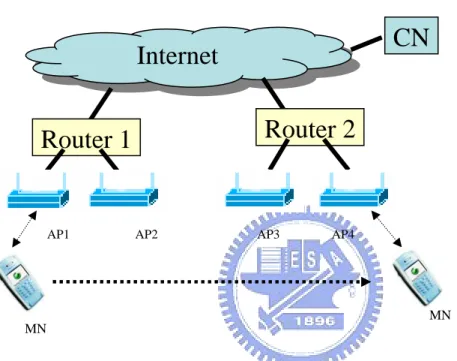
(9) Chapter 1 Introduction In the recently years, IEEE 802.11[1]-based wireless local area networks (WLANs) have seen immense growth. A lot of cities invest heavily in the public wireless LAN to build up their WiFi cities. It will expand the wireless access coverage while maintaining continuous connectivity from one wireless LAN to another. Because of the mobility-enabling nature of wireless networks, there is opportunity for many promising multimedia and peer-to-peer applications (such as VoIP, WiFi phones, mobile video conferencing and chat). Also, many believe that WLANs may become or supplement via hot spots the next generation 4G wireless networks. Unfortunately, the network connection as perceived by the application can suffer from the jittery handoff latencies and packet loss. A Handoff occurs when a mobile station moves beyond the radio range of one AP, and enters another BSS (at the MAC layer). During the handoff, management frames are exchanged between the station (STA) and the AP. Also the APs involved may exchange certain context information (credentials) specific to the station. Consequently, there is latency involved in the traditional handoff process during which the STA is unable to send or receive traffic. In [2], significant latency is reported in the generic wireless LAN card. Figure 1 shows the generic architecture of the wireless network. The network includes two routers to separate the two subnetworks. MN communicates with CN through AP1 and Router 1.. After handoff with. AP2/AP3/AP4, MN changes its subnet to Router 2. In this paper, we propose a semi-soft scheme to ensure that when MN roams from AP1 to AP4 there is no packet loss. We also provide an architecture to fix the problem in layer 3. 1.. The author proposes that:. Use IEEE 802.11 power management property to create two logical -9-.
(10) links in two APs when handoff. 2.. Combine layer 2 and layer 3. After the MN connects with the new AP, it will trigger the Layer 3 to get the new IP.. 3.. Get an IP address per link.. 4.. Create a NAT for the host. Our architecture will handle the layer 2 and layer 3 protocol. The host doesn’t have to change anything when handoff.. CN. Internet Router 2. Router 1. AP1. AP2. AP3. AP4. MN MN. Figure 1 Typical architecture of the wireless network. - 10 -.
(11) Chapter 2 Background and Related Work 2.1 Background 2.1.1 Handoff A handoff, or handover, is the process in which a mobile device is moved from one cell to the next in order to maintain a radio connection with the network.. 2.1.1.1 Hard Handoff In hard handoff, the radio connection is broken between the network and the mobile host before a new radio connection is established with the network in the target AP. Hard handoffs usually require a change of frequency. It is based on a simple approach that trades off some packets loss in exchange for minimizing handoff signaling rather than trying to guarantee zero packet loss. Hard handoff causes packet losses proportional to the round-trip time and to the downlink packet rate.. 2.1.1.2 Soft Handoff In soft handoff, the mobile always keeps at least one radio link established during handoff. If the mobile want to work with soft handoff, it must handoff in the same channel with one RF module or it has two RF modules to support the difference channel.. 2.1.1.3 Semi-Soft Handoff Semi-soft handoff is a special case of soft handoff. It exploits the notion that some mobile hosts can simultaneously receive packets from the new and old AP during handoff. During semi-soft handoff a mobile host may be in contact with either the old or the new AP and receives packets from them. - 11 -.
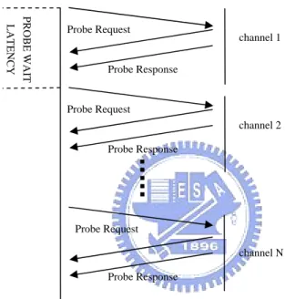
(12) 2.1.2 Scanning in IEEE 802.11 2.1.2.1 Active Scanning Active scanning involves the generation of Probe frames and the subsequent processing of received Probe Response frames. Figure 2 shows the messages in an active scan. The STA transmits a probe request message and waits for responses from APs on each channel.. Probe-Wait latency denotes the time that STA waits on. one particular channel after sending the probe request. LATENCY. PROBE WAIT. Probe Request. channel 1. Probe Response. Probe Request channel 2 Probe Response. Probe Request channel N Probe Response. Figure 2 Active Scanning Procedure. 2.1.2.2 Passive Scanning In passive scanning, the STA shall listen to each channel scanned for a duration time. If the mobile want to collect all of the AP’s information, it must stay at each channel more than one beacon period time.. 2.1.3 Probe function The probe feature is defined under the IEEE 802.11 MAC active scan function and the standard specifies a scanning procedure as follow: For each channel to be scanned, I.. STA sends a probe request with broadcast destination, SSID, - 12 -.
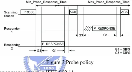
(13) and broadcast BSSID. II. STA starts a ProbeTimer. III. If medium is not busy before the ProbeTimer reaches MinChannelTime, scan the next channel, else when ProbeTimer reaches MaxChannelTime, process all receive probe responses and proceed to next channel. (Refer to Figure 3). Figure 3 Probe policy. 2.1.4 Power management in IEEE 802.11 When changing Power Management mode, the STAs shall inform the AP by modifying the Power Management bits within the Frame Control field of transmitted frames. The AP shall not arbitrarily transmit MSDUs to STAs operating in a power-saving mode, but shall buffer MSDUs and only transmit them at designated times. The STAs that currently have buffered MSDUs with the AP are identified in a traffic indication map(TIM), which shall be included as an element within all beacons generated by the AP. A STA will be able to determine that an MSDU is buffered upon receiving and interpreting a TIM. A STA shall remain in its current Power Management mode until it informs the AP of a Power Management mode change via a successful - 13 -.
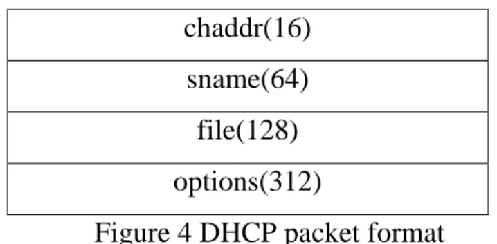
(14) frame exchange. Power Management mode shall not changes during any single frame exchange sequence.. 2.1.5 DHCP[3] DHCP stands for “Dynamic Host Configuration Protocol” and is a means for networked computers to obtain their TCP/IP networking setting from a central server.. Specifically, a DHCP server assigns IP. address and other TCP/IP configuration parameters automatically upon request from a DHCP client. DHCP is explained in further detail at RFC 1541. DHCP is an extension of BOOTP (Bootstrap Protocol), the previous IP allocation specification.. Consequently, the legacy BOOTP devices can. communicate with DHCP servers and allow DHCP request to pass cross routers running BOOTP forwarders. This level of backward compatibility make it easy for administrators to upgrade their network devices from BOOTP to DHCP as needed, without having to replace all of the clients at once or having to upgrade all of the routers. DHCP uses the client-server model and is conducted over UDP.. 2.1.5.1 DHCP Message Format DHCP uses the same packet format as BOOTP for compatibility. DHCP server can respond to BOOTP client and vice versa. Figure 4 show the packet format of DHCP header. Op(1). Htype(1). hen(1). hops(1). xid(4) Secs(2). Flags(2) ciaddr(4) yiaddr(4) siaddr(4) giaddr(4). - 14 -.
(15) chaddr(16) sname(64) file(128) options(312) Figure 4 DHCP packet format Table 1 show the description of fields in a DHCP message. Table 2 show the message types for DHCP. Field op. Description Message op code/message type 1: BOOTREQUEST, 2:BOOTRELY. htype. Hardware address type. hlen. Hardware address length. hops. Client sets to zero, optionally used by relay-agents when booting via a relay-agent Transaction ID, a random number chosen by the. xid. client, used by the client and server to associate messages and responses between a client and a server.. secs flags. Filled in by client, seconds elapsed since client started trying to boot. Flags Client. ciaddr. IP. address;filled. in. by. client. in. DHCPREQUEST if verifying previously allocated configuration parameters.. yiaddr. Your (client) IP address. IP address of next server to use in bootstrap;. siaddr. returned in DHCPOFFER, DHCPACK and DHCPNAK by server.. giaddr. Relay agent IP address, used in booting via a relay-agent.. chaddr. Client hardware address. sname. Optional server host name, null terminated string. - 15 -.
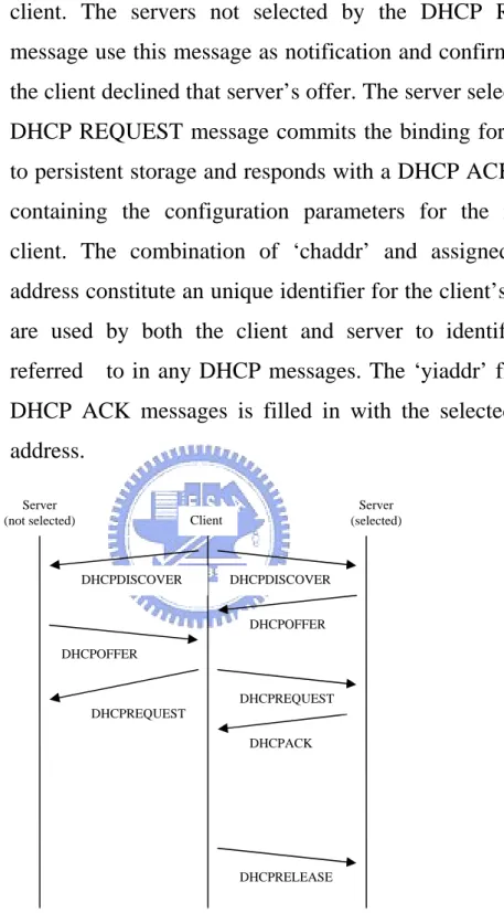
(16) Boot file name, null terminated string; “generic” file. name or null in DHCPDISCOVER, filly qualified directory-path name in DHCPOFFER.. option. Optional parameters field.. Table 1 DHCP field description. Message. Description. DISCOVER. A client broadcasts to recognize servers.. OFFER. Servers respond with proposal of parameters.. REQUEST. The client broadcasts to the preferable server. An implicit decline to others.. ACK. The server assigns an IP address.. NAK. The server rejects the request from the client. DECLINE. The client found a problem with an assigned address.. RELEASE. The client returns the assigned address before its lease expires. Table 2 DHCP message type. 2.1.5.2 Protocol flow of DHCP The following summarizes of the protocol exchanges between DHCP clients and servers, in reference to the DHCP messages described in table 2. The timeline diagram in figure 5 shows the timing relationships in a typical client-server interaction. If the client already knows its address, some steps may be omitted. I.. The client broadcasts a DHCP DISCOVER message on its local physical subnet. The DHCP DISCOVER message may include options that suggest values for the network address and - 16 -.
(17) lease duration. BOOTP relay agents may ass the message on the DHCP servers not on the same physical subnet. II. Each server may respond with a DHCP OFFER message that include an available network address in the ‘yiaddr’ filed (and other configuration parameters in DHCP options). Servers does not need to reserve the offered network address, although the protocol will work more efficiently if the server avoids allocating the offered network address to another client. The server unicasts the DHCP OFFER message to the client (using the DHCP/BOOTP relay agent if necessary) if possible, or may broadcast the message to a broadcast address (preferably 255.255.255.255) on the client’s subnet. III. The client receives one or more DHCP OFFER messages from one or more servers. The client may choose to wait for multiple responses. The client chooses one server from which to request configuration. parameters,. based. on. the. configuration. parameters offered in the DHCP OFFER messages. The client broadcasts a DHCP REQUEST message that MUST include the ‘server identifier’ option to indicate which server it has selected, and may include other options specifying desired configuration values. This DHCP REQUEST message is broadcast and relayed through DHCP/BOOTP relay agents. To help ensure that any DHCP/BOOTP relay agents forward the DHCP REQUEST message to the same set of DHCP servers that received the original DHCP DISCOVER message, the DHCP REQUEST message must use the same value in the DHCP message header’s ‘secs’ field and be sent to the same IP broadcast address as original DHCP DISCOVER message if the client receives no DHCP OFFER messages. - 17 -.
(18) IV. The servers receive the DHCP REQUEST broadcast from the client. The servers not selected by the DHCP REQUEST message use this message as notification and confirmation that the client declined that server’s offer. The server selected in the DHCP REQUEST message commits the binding for the client to persistent storage and responds with a DHCP ACK message containing the configuration parameters for the requesting client. The combination of ‘chaddr’ and assigned network address constitute an unique identifier for the client’s lease and are used by both the client and server to identify a lease referred. to in any DHCP messages. The ‘yiaddr’ field in the. DHCP ACK messages is filled in with the selected network address. Server (not selected). Server (selected). Client. DHCPDISCOVER. DHCPDISCOVER DHCPOFFER. DHCPOFFER DHCPREQUEST DHCPREQUEST DHCPACK. DHCPRELEASE. Figure 5 IP Address assigned procedure. 2.1.6 NAT[4] NAT is an acronym for Network Address Translation. It is a commonly used IP translation and mapping technology. To a typical - 18 -.
(19) home network user, it is a technology that allows one’s home network to share internet access. Using a device or piece of software that implements NAT allows an entire home network to share a single internet connection over a single legal publicly accessible IP address. A single cable mode, DSL modem, or even 56k modem could connect all the computers in your home to the internet simultaneously. Additionally, NAT keeps your home network fairly secure from hackers.. 2.2 Relation Work There are a lot of proposals to solve the packet loss when dealing with handover and to reduce the latency of handoff. They improve the handoff in many ways, such as modifying the MAC layer procedure, changing the network architecture, the network environment, and so on.. 2.2.1 Soft Handoff In [5], the authors proposed the soft handoff in the wireless system. They expect that there are more than two physical interfaces to connect with the internet. They create two modules for the MN and FA. SHIP duplicator unit runs at the SHIP-FA and is responsible for duplicating and forwarding the stream of packets of any MN experiencing a soft handoff process. The SHIP combiner unit is implemented only by MN. It combines the received descriptions of each packet and forwards the packet to the higher layer for further processing. The architecture is good for the heterogeneous network or there is a lot of hardware. Because there is a lot of hardware, it should connect with the AP or BS when it detects the AP or BS. There is no layer 2 issue. In the generic wireless LAN, there is one radio in the hardware, so it cannot use soft handoff to connect with two APs. This paper is not good for the wireless LAN, except we add more hardware in the system. - 19 -.
(20) 2.2.2 Inter Access Point Protocol In [6], IEEE defines IAPP in 802.11f. The protocol is defined for wireless LAN handoff. It must be implemented in the MN(Mobile Node), AP(Access Point), and Radius Server. When the MN starts the handoff procedure, the new AP will get the MN’s information from Radius Server when it receives the Re-association Request frame. The MN doesn’t have to exchange the information every time during handoff. IAPP is an ideal solution to solve the layer 2 handover problem.. It. reduces the handoff latency issue in layer 2, although it cannot fix the packet loss problem. IAPP does not address handoff for layer 3.. 2.2.3 Link Layer Assisted Mobile IP Fast Handoff Method over Wireless LAN Network In [7], the author proposed a network environment to fix the handoff problem. The proposed solution adds a MAC bridge between two networks. This bridge is able to detect the handoff event when the mobile node handoff.. Thereafter, the bridge will forward the packet. after the mobile node handoff. In this method, it will fix the packet loss problem in layer 3. However, there is a potential risk of packet loss in layer 2 during handoff.. 2.2.4 Fast Inter-AP Handoff Using Predictive Authentication Scheme in a Public Wireless LAN In [8], the authors proposed a fast inter-AP handoff scheme. Under this scheme, a FHR(Frequent Handoff Region) is defined. All of the APs in the FHR will get the mobile node information once a mobile node is associated with an AP. When the mobile node handoff, it does not have to exchange the message with the new AP as the new AP - 20 -.
(21) already has its information, should this AP belongs to the FHR. The scheme reduced the handoff latency because it reduces the messages to be exchanged. It doesn’t fix the packet loss problem during handoff. The scheme uses the backbone to exchange the mobile node information between APs.. However, this would create a heavy. loading in public LAN should the mobile node handoff frequently. This scheme has to select the FHR for each mobile node. It is a heavy loading for the AAA if there are a lot of mobile nodes. Our scheme uses distribution system so there is a few overhead for all of the nodes.. - 21 -.
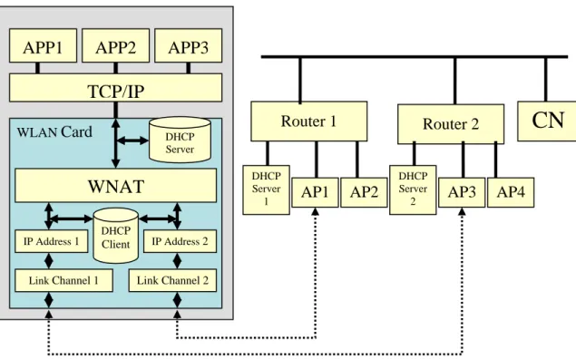
(22) Chapter 3 Layer 2 and layer 3 Semi-Handover Schemes In this section, we present the proposed semi-soft scheme in IEEE 802.11 wireless LAN and our architecture in mobile node. For simplicity of presentation, we assume that a mobile node is in the coverage of two APs during handoff. Figure 6 illustrates the author’s proposed architecture. We add some functions in the wireless LAN card. The sequence of events is as follows: 1. DHCP server: When the mobile node asks the IP address, the DHCP server will assign an IP address for it. It should be always the same IP address. 2. WNAT(Wireless NAT): It will decide which link we want to transmit the data and it will change the IP address of the packets to IP address 1 or IP address 2 (based on the link). It always transfers to the IP address (the DHCP sever assigns) when it receive a packets from the wireless. 3. DHCP client: It will try to get the new IP address when the mobile node connects with the new AP. We combine the network layer and IP layer algorithm. In network layer, when it connects with the new AP, it will trigger the DHCP client to start the IP assignment procedure. DHCP client will get the IP address for each links.. - 22 -.
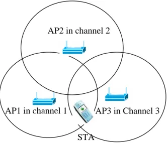
(23) APP1. APP2. APP3. TCP/IP Router 1. WLAN Card. CN. Router 2. DHCP Server DHCP Server 1. WNAT. AP1. AP2. DHCP Server 2. AP3. AP4. DHCP IP Address 1. Link Channel 1. Client. IP Address 2. Link Channel 2. Figure 6 System Architecture of mobile node. In reference to appendix 1, there are a lot of latencies occurred during handoff. We set out to address layer 2 and layer 3 latencies, with the following objectives: First, reduce the discovery time.. Second, recude the handoff time. of layer 2 and layer 3. 1. Reducing Discovery time In Figure 7, it shows a generic wireless environment, the mobile node (STA) connects to AP1 in channel 1. When it start the scanning procedure, it send a null frame with power management bit on to AP1, AP1 will change STA’s mode to doze and it will keep STA’s data in the buffer before STA change its status. STA can change its channel to scan the other channels. After the scanning, STA changes back the current channel, and then it send a null frame with the power management bit is off to AP1. AP1 changes STA’s status to awake. AP1 sends the data to STA if it keeps any data in the buffer. Based on this procedure, the STA does not lost any data from AP1 and it will keep the newest wireless information in the meantime. refer to Figure 8.) - 23 -. (please.
(24) AP2 in channel 2. AP1 in channel 1. AP3 in Channel 3 STA. Figure 7 Generic wireless environment. STA No data traffic in STA. Scan the prefer. Null data(1). AP1. Probe Request Get the information. AP3 Probe Response Active AP sends the Null data(0). AP1. Figure 8 mobile node scanning procedure. 2. The handoff time of layer 2 and layer 3 When the mobile node detects the radio signal strength of the old - 24 -.
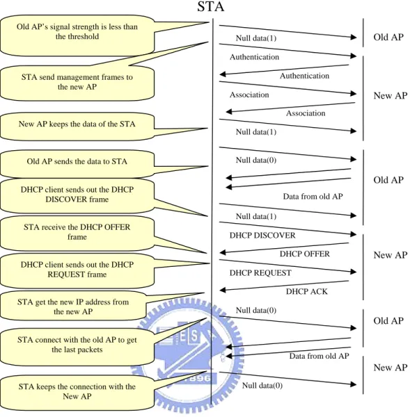
(25) AP, and find it to be less than the threshold while the radio signal strength of the new AP is increasing, then it will start the handoff procedure by initiating the following sequence of events: 1. Send a null frame with power management bit is on to the old AP, the old AP will change STA’s status to doze and it will keep the STA’s data in the buffer. 2. STA change its channel to the new AP’s channel. It sends the authentication frame to the new AP. The new AP will reply its authentication frame. 3. STA sends the association frame to the new AP. The new AP will reply its association frame. The STA is connected with the new AP. 4. STA sends a null frame with the power management bit is on to the new AP. The new AP will keep STA’s data in its buffer. 5. STA changes its channel to the old AP’s channel then send a null frame with the power management bit is off to the old AP, the old AP will send the STA’s data which it keeps in its buffer. 6. After receiving all of the data from the old AP, the STA sends a null frame with power management bit on to the old AP again, and then it triggers the DHCP client to send the DHCP DISCOVER frame. 7. When the STA receive the DHCP DISCOVER frame from the host, it sends the packet to the new AP with power management bit off. Thereafter, it will receive the DHCP OFFER from the DHCP server. 8. The DHCP client then sends the DHCP REQUEST and STA will transmit it to the new AP. - 25 -.
(26) 9. The DHCP server replies with the DHCP ACK, and then the STA will get the new IP address. The STA will record the IP address with the BSSID of the AP. 10. The STA sends a null frame with the power management bit on to the new AP, then it changes its channel to the old one. 11. The STA sends a null frame with the power management bit is off to the old AP, then it receive the data from the old AP. 12. The STA sends a null frame with the power management bit off to the new AP.. After which, it keeps the. connection with the new AP.. Please refer to Figure 9 for illustration of the series of events.. - 26 -.
(27) STA Old AP’s signal strength is less than the threshold. Old AP. Null data(1) Authentication Authentication. STA send management frames to the new AP Association. New AP Association. New AP keeps the data of the STA Null data(1) Null data(0). Old AP sends the data to STA. Old AP DHCP client sends out the DHCP DISCOVER frame. Data from old AP Null data(1). STA receive the DHCP OFFER frame. DHCP DISCOVER DHCP OFFER. DHCP client sends out the DHCP REQUEST frame. New AP. DHCP REQUEST DHCP ACK. STA get the new IP address from the new AP. Null data(0). Old AP STA connect with the old AP to get the last packets. Data from old AP. New AP Null data(0). STA keeps the connection with the New AP. Figure 9 Handoff procedure in layer 2 and layer 3. - 27 -.
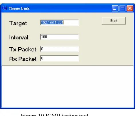
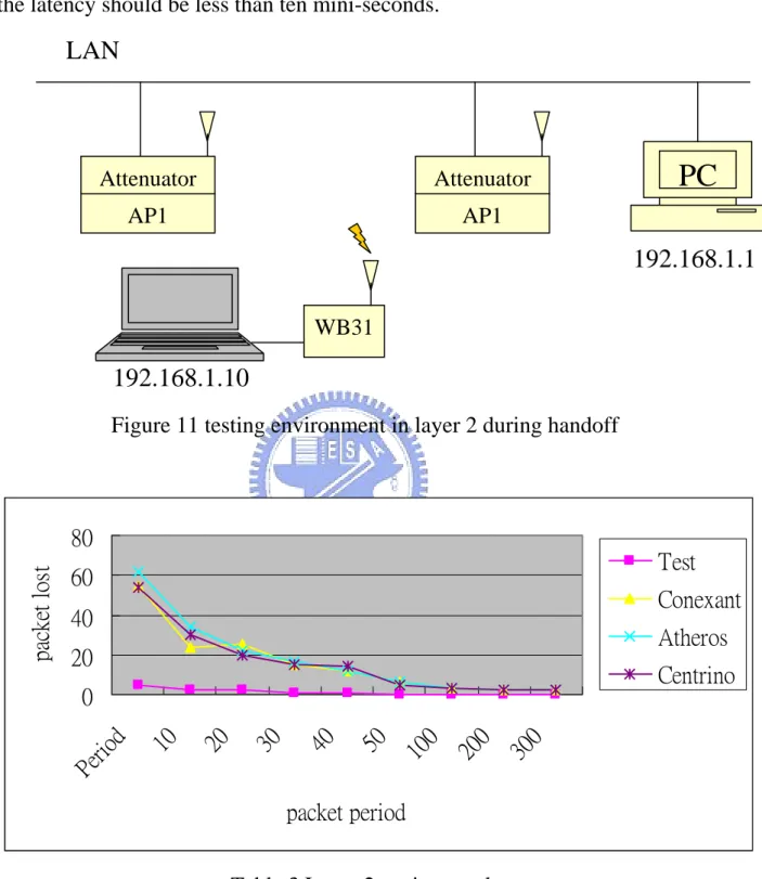
(28) Chapter 4 Implementation and Results Our semi-soft scheme is implemented in Marvell WB31 platform. This platform is a SOC (System on chip). It includes a ARM based MAC and Marvell ‘s baseband and radio. We use ECOS OS in this platform and we combine the layer 2 and layer 3 protocol in this platform. For testing, we use ICMP protocol to test the packet loss because this protocol will not retry any packets. Figure 10 shows the tool.. Figure 10 ICMP testing tool Figure 11 show the testing environment of layer 2 handoff. We use one notebook to connect with WB31 through the Ethernet. Because the radio signal strength is strong, we add the attenuator in the AP.. When we adjust the radio. power of the AP, it will simulate the movement of WB31. We start the testing tool in the notebook and setup the target address to the PC. We also test Centrino/Conexant/Atheros wireless LAN cards on the same notebook. Table 3 shows the results of our testing. Based on the results, we find the generic wireless LAN cards do the hard handoff, so they need more one hundred mini-seconds to do the handoff.. In our schemes, the handoff time is less than - 28 -.
(29) fifty mini-seconds.. Upon analysis of the results, we learnt that the latency of. our platform is created by the software and hardware limitation. If we can fix it, the latency should be less than ten mini-seconds.. LAN. Attenuator. Attenuator. AP1. AP1. PC 192.168.1.1. WB31. 192.168.1.10 Figure 11 testing environment in layer 2 during handoff. packet lost. 80. Test. 60. Conexant. 40. Atheros. 20. Centrino 30 0. 20 0. 10 0. 50. 40. 30. 20. 10. Pe r io d. 0. packet period Table 3 Layer 2 testing results Figure 12 shows the environment during layer 2 and layer 3 handoff. WB31will try to get the IP address when it connect with the new AP. Table 4 shows the results, including layer 2 and layer 3 handoffs. Based on - 29 -.
(30) the results, it is learnt that the generic wireless LAN cards implement the handoff using hard handoff.. Consequently, after layer 2 handoff, they need. more time to get the IP address.. The author’s propose solution does not need. more time to get the IP address because we get the IP address during semi-soft handoff. Subnet1 192.168.1.x. Router1. Router2 Subnet3 192.168.3.x. Subnet2 192.168.2.x. PC. Attenuator. Attenuator. Attenuator. Attenuator. AP1. AP2. AP3. AP4. 192.168.1.1. WB31. Figure 12 testing environment in layer 3 during handoff. - 30 -.
(31) Packet lost. 6 5 4 3 2 1 0. Test. 10 20 30 40 50 100 200 300 400 500 600 700 Packet period. Table 4 Layer 3 testing results. - 31 -.
(32) Chapter 5 Conclusion and Future Work Base on our testing results, we verified that our schemes and architecture is able to address the layer 2 and layer 3 handoff issues. The host doesn’t have to handle anything during handoff. We still have the layer 4 problem during handoff because some applications will handle the remote IP address. So, our schemes must co-work with the applications during IP changes. The popular schemes in layer 4 is Mobile IP or SCTP.. Mobile IP proposal requires building up a complex environment which. includes the home agent and foreign agent. SCTP is a peer to peer protocol that is based on IP layer.. These may be a good mix to combine with our. schemes.. - 32 -.
(33) Reference [1] IEEE. IEEE Standard 802.11, Part Ⅱ: Wireless LAN medium access control (MAC) and physical layer (PHY) specifications.Washington: IEEE Computer Society Press, 1999 [2] M Arunesh, S Minho, et al. An empirical analysis of the IEEE 802.11 MAC layer handoff process. http://www.cs.umd.edu/~waa/pubs/handoff-lat-acm.pdf, 2002-05 [3] R. Droms, “Dynamic Host Configuration Protocol”, IETF RFC1541, October 1993. [4] K. Egevang, “The IP Network Address Translator”, IETF RFC1631, May 1994 [5] Bechir Hamdaoui and Parameswaran Ramanathan, "A Network-Layer Soft Handoff Approach for Mobile Wireless IP-Base Systems", http://www.ece.wisc.edu/~wander/papers/JSAC04_hamdaoui.pdf [6] IEEE. IEEE Draft 802.11f/D5, Recommended practice for multi-vendor access point interoperability via an inter-access point protocol across distribution system supporting. Washington: IEEE Computer Society Press, 2002 [7]H. Yokota et al., “Link Layer Assisted Mobile IP Fast handoff Method over Wireless LAN Networks”, in Proc. MOBICOM 2002, September 2002. [8] Sangheon Pack, Yanghee Choi. Fast inter-AP handoff using Predictive-authentication scheme in public wireless LAN. http:. citeseer.ist.psu.edu/pack02fast. html, 2002-08. - 33 -.
(34) Appendix Source: A. Alimian and B. Aboba, Doc.: IEEE 802.11-04/0377r1, slide 5. . Layer. L2. IPv4 Best. IPv4 Worst Case. IPv6 Best Case. IPv6 Worst Case. Item. Case (ms). (ms). (ms). (ms). 802.11 scan. 0. 1 sec (wait for. (passive). (cached). Beacon). 0 (cached). Beacon). 20. 300. 20. 300. 4. 20. 4. 20. 20. 80. 20. 80. 750. 1200. 750. 1200. 150. 300. 150. 300. 10. 80. 10. 80. 1 sec (wait for. 802.11 scan L2. (active) 802.11 assoc/reassoc. L2. (no IAPP) 802.11 assoc/reassoc. L2. (w/ IAPP) 802.1X authentication. L2. (full) 802.1X Fast. L2. resume Fast handoff (4-way. L2. handshake only) DHCPv4 (6to4. L3. scenario only). 200. 500. 0. 0. L3. IPv4 DAD. 0 (DNA). 3000. 0. 0. L3. Initial RS/RA. 0. 0. 5. 10. 0. 0. 0. 1500. Wait for more L3. RAs. 0 (Optimistic L3. IPv6 DAD. 0. 0. DAD). 1000. L3. MN-HA BU. 0. 200. 0. 200. L3. MN-CN BU. 100. 200. 100. 200. L4. TCP adjustment. 0. Varies. 0. Varies. - 34 -.
(35)
數據
+7
相關文件
A host connecting to the outside network is allocated an external IP address from the address pool managed by NAT... Flavors of
An adaptation layer is used to support specific primitives as required by a particular signaling application. The standard SS7 applications (e.g., ISUP) do not realize that
Responsible for providing reliable data transmission Data Link Layer from one node to another. Concerned with routing data from one network node Network Layer
浮尖 浮尖 第二層 第二層 第二層 第二層(STEM (STEM (STEM (STEM學會 學會 學會 學會))))、第三層培訓 、第三層培訓
The simulation environment we considered is a wireless network such as Fig.4. There are 37 BSSs in our simulation system, and there are 10 STAs in each BSS. In each connection,
This study proposed the Minimum Risk Neural Network (MRNN), which is based on back-propagation network (BPN) and combined with the concept of maximization of classification margin
In this paper, we have studied a neural network approach for solving general nonlinear convex programs with second-order cone constraints.. The proposed neural network is based on
Taking second-order cone optimization and complementarity problems for example, there have proposed many ef- fective solution methods, including the interior point methods [1, 2, 3,
![[102-2] WNFA lab4 - A Tiny Wireless Sensor Network](data:image/gif;base64,R0lGODlhAQABAIAAAP///wAAACH5BAEAAAAALAAAAAABAAEAAAICRAEAOw==)