Manipulating terahertz wave by a magnetically
tunable liquid crystal phase grating
Chia-Jen Lin,1 Yu-Tai Li,2 Cho-Fan Hsieh,1 Ru-Pin Pan,1,* and Ci-Ling Pan2,*
1Department of Electrophysics, National Chiao Tung University, Hsinchu, Taiwan 30010, R.O.C. 2Department of Photonics and Institute of Electro-Optical Engineering, National Chiao Tung University,
Hsinchu, Taiwan 30010, R.O.C.
*Corresponding authors: [email protected], [email protected]
Abstract: This investigation demonstrates the feasibility of a magnetically
tunable liquid crystal phase grating for the terahertz wave. The phase grating can be used as a beam splitter. The ratio of the zeroth and first-order diffracted THz-beams (0.3 THz) polarized in a direction perpendicular to that of the grooves of the grating can be tuned from 4:1 to 1:2. When the THz wave is polarized in any other direction, this device can be operated as a polarizing beam splitter.
©2008 Optical Society of America
OCIS codes: (320.7080) Ultrafast devices; (230.3720) Liquid-Crystal devices;
(050.1950) Diffraction gratings; (320.0320) Tera-Hertz ; (230.1360) Beam splitters References and links
1. B. Ferguson and X.-C. Zhang, “Materials for terahertz science and technology,” Nat. Maters. 1, 26-33 (2002).
2. D. Mittleman, Terahertz Imaging, Sensing with THz radiation (Spring-Verlag, New York 2002). 3. P. H. Siegel, “Terahertz technology,” IEEE Trans. Microwave Theory Tech. 50, 910-928 (2002).
4. A. Filin, M. Stowe, and R. Kersting, “Time-domain differentiation of terahertz pulses,” Opt. Lett. 26, 2008-2010 (2001).
5. F. Garet, J. –L. Coutaz, M. Narzarov, E. Bonnet, O. Parriaux, and G. Racine, “THz time-domain spectroscopy study of grating couplers and segmented grating filters,” Digest of Joint 29th Int. Conf. on Infrared and Millimeter Waves and 12th Int. Conf. on Terahertz Electron. 181-182 (2004).
6. R. Kersting, G. Strasser, and K. Unterrainer, “Terahertz phase modulator,” Electron. Lett. 36, 1156-1158 (2000).
7. J. Chen, P. J. Bos, H. Vithana, and D. L. Johnson, “An electro-optically controlled liquid crystal diffraction grating,” Appl. Phys. Lett. 67, 2588-2590 (1995).
8. Jae-Hong Park, Chang-Jae Yu, Jinyool Kim, Sung-Yeop Chung, and Sin-Doo Lee, “Concept of a liquid-crystal polarization beamsplitter based on binary phase gratings,” Appl. Phys. Lett. 83, 1918-1920 (2003). 9. Fuzi Yang and J. R. Sambles, “Microwave liquid-crystal variable phase grating,” Appl. Phys. Lett. 85,
2041-2043 (2004).
10. F. Vita, A. Marino, V. Tkachenko, G. Abbate, D. E. Lucchetta, and F. Simoni, “Visible and near-infrared characterization and modeling of nanosized holographic-polymer-dispersed liquid crystal gratings,” Phys. Rev. E 72, art. 011702 (2005).
11. H.-Y, Wu, C.-F. Hsieh, T.-T. Tang, R.-P. Pan, and C.-L. Pan, “Electrically tunable room-temperature 2π liquid crystal terahertz phase shifter,” IEEE Photon. Technol. Lett. 18, 1488-1490 (2006).
12. C.-Y. Chen, C.-F. Hsieh, Y.-F. Lin, C.-L. Pan, and R.-P. Pan, “Liquid-crystal-based terahertz tunable Lyot filter,” Appl. Phys. Lett. 88, art. 101107 (2006).
13. J. W. Goodman, Introduction to Fourier Optics, 2nd ed. (McGraw-Hill, 1996).
14. C.-Y. Chen, C.-F. Hsieh, Y.-F. Lin, R.-P. Pan, and C.-L. Pan, “Magnetically tunable room-temperature 2π liquid crystal terahertz phase shifter,” Opt. Express 12, 2625-2630 (2004).
15. P. G. De Gennes and J. Prost, The Physics of Liquid Crystals, 2nd ed., (Oxford, New York, 1993). 16. C.-L. Pan, C.-F. Hsieh, R.-P. Pan, M. Tanaka, F. Miyamaru, M. Tani, and M. Hangyo, “Control of
enhanced THz transmission through metallic hole arrays using nematic liquid crystal,” Opt. Express 13, 3921-3930 (2005).
1. Introduction
Recently, terahertz (THz) technology and its applications have progressed rapidly [1-3]. Nonetheless, essential quasi-optic components in the THz range are relatively under-developed. Periodic structures such as gratings are commonly used to control electromagnetic waves. In the far infrared, time-domain differentiation of THz pulses was realized with a metallic grating [4]. The use of gratings as couplers and filters was also investigated [5, 6]. On the other hand, gratings with liquid-crystal-enabled functionalities have been extensively studied as spectrometers, filters, beam splitters, and holographic optical elements for visible and microwave wavelengths [7-10]. Moreover, various tunable THz devices based on nematic liquid crystals (NLC), such as phase shifters and filters that are controlled either electrically or magnetically, have been demonstrated [11,12]. This work presents for the first time a tunable liquid crystal (LC) phase grating in the THz frequency range. The diffraction effect of the grating is magnetically switchable by changing the effective refractive index of the NLC.
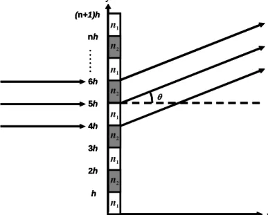
A generic binary phase grating is sketched in Fig. 1. It contains alternate sections of two materials with different refractive indices. The electric fields of electromagnetic waves that pass through materials 1, 2 and the total field E detected at an angle of θ from the incident beam can be written as,
), ( ) ( , ) ( , ) ( 2 1 0 1 sin ( ) 0 2 1 1 ( ) sin 0 1 2 2 1 1 θ θ θ θ κ κ E E E dy e e E E dy e e E E even n )h (n nh kd i n θ iky odd n )h (n nh kd i n θ iky + = = =
∑ ∫
∑ ∫
= + + = + + (1)where E0 is the amplitude of the incident electric field, θ is the diffraction angle, k is the wave
number of the electromagnetic wave in free space, h is the width of each material, d is the thickness of the grating, and n1+iκ1 and n2+iκ2 are complex refractive indices of materials 1
and 2, respectively.
Fig. 1. Schematic of a generic binary phase grating.
For an ideal phase grating, the diffraction efficiency of the m-th order diffracted wave, defined as the intensity ratio of the diffracted beam to that of the incident beam, is given by,
n1 x y h 2h 3h . . . . . . nh (n+1)h 4h 5h 6h θ n2 n1 n2 n1 n2 n1 n2 n1 n1 x y h 2h 3h . . . . . . nh (n+1)h 4h 5h 6h θ n2 n1 n2 n1 n2 n1 n2 n1 n1 x y h 2h 3h . . . . . . nh (n+1)h 4h 5h 6h θ n1 x y h 2h 3h . . . . . . nh (n+1)h 4h 5h 6h θ n2 n1 n2 n1 n2 n1 n2 n1
2 2 / 2 / ) / 2 ( 2 1
∫
− − Λ Λ Λ Λ e e dy my i iφ π (2)where φ is the y-dependent phase shift of the grating for one grating period of Λ [13]. Following Ref. 8, we can write
⎩ ⎨ ⎧ ≠ Δ = Δ = 0, if ) 2 / ( sin )] 2 / sin( ) / 2 [( , 0 if ) 2 / ( cos 2 2 2 m m m m m φ π π φ η (3)
where Δφ is the relative phase difference between two adjacent domains in the phase grating. For Δφ = (2n+1)π (n = integer), the diffraction efficiencies of the odd orders (m = ±1, ±3,
±5,…) are maximal. Equation (3) reveals that the diffraction efficiency of the 3rd order η±3 =
4.5% is nine times smaller than that of the 1st order η±1= 40.5%. Therefore, we will only
consider the 0th and 1st orders of the diffracted beam in this work. Equations (2) and (3) were used as a guide for designing parameters of the grating. Because only a finite number of grooves are fabricated instead of the infinite number of elements assumed in Eqs. (2) and (3), experimentally observed efficiencies are expected to be smaller.
2. Experimental methods
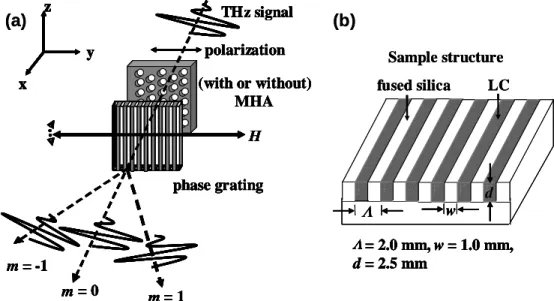
Figure 2 illustrates schematically our experimental setup and structure of the LC phase grating, which was designed such that the 1st order diffraction efficiency would be highest around 0.3 – 0.5 THz. Parallel grooves having a period of 2.0 mm, a width of 1.0 mm, and a groove-depth of 2.5 mm were fabricated on a 10.0 mm thick fused silica substrate, for which the refractive index is 1.95 in the THz frequency region (0.2 – 0.8 THz) [11]. The grooves were filled with the NLC, E7 (Merck), and sealed with a sheet of Teflon.
H THz signal m = 1 m = 0 m = -1 phase grating x y z polarization (with or without) MHA H THz signal m = 1 m = 0 m = -1 phase grating x y z x y z polarization (with or without) MHA Λ= 2.0 mm, w = 1.0 mm, d = 2.5 mm Sample structure Λ w Λ= 2.0 mm, w = 1.0 mm, d = 2.5 mm fused silica d LC
(a)
(b)
H THz signal m = 1 m = 0 m = -1 phase grating x y z polarization (with or without) MHA H THz signal m = 1 m = 0 m = -1 phase grating x y z x y z polarization (with or without) MHA Λ= 2.0 mm, w = 1.0 mm, d = 2.5 mm Sample structure Λ w Λ= 2.0 mm, w = 1.0 mm, d = 2.5 mm fused silica d LC H THz signal m = 1 m = 0 m = -1 phase grating x y z x y z polarization (with or without) MHA H THz signal m = 1 m = 0 m = -1 phase grating x y z x y z polarization (with or without) MHA Λ= 2.0 mm, w = 1.0 mm, d = 2.5 mm Sample structure Λ w Λ= 2.0 mm, w = 1.0 mm, d = 2.5 mm fused silica d LC(a)
(b)
Fig. 2. (a). Experimental setup; H: magnetic field, MHA: metallic hole array used as narrow band filter. (b) Construction of the LC phase grating; dimensions were shown.
The dimensions of the grating were designed to have the maximum range of adjustment for the beam splitting ratio at 0.3 THz. Since E7 is a birefringent material with positive diamagnetic anisotropy, the molecules tend to be aligned parallel to the direction of the applied magnetic field. The applied magnetic field in this work was ~ 1800 G, much higher than the threshold field for reorienting the LC, Hc ~ 100 G. We can thus assume that the average direction of LC molecules are reoriented parallel to the magnetic field direction. The incident THz beam was polarized along the y-direction in our setup. The refractive index of
E7 [14] could thus be switched from the value for the ordinary wave (THz field polarized perpendicular to H, no=1.58) to that for the extraordinary wave (THz field polarized parallel to
H, ne=1.71) by changing direction of the magnetic field from the z-direction to the y-direction. The corresponding imaginary indices are κo (0.01) to κe (0.007). A block of fused silica identical in dimension to that of the grating with a Teflon sheet was prepared as the reference. The data presented below, were obtained at room temperature 23±0.5°C.
A photoconductive antenna-based Terahertz time-domain spectrometer (THz-TDS) [16] was utilized to measure the 0th order diffraction spectra of the device. Briefly, the pump beam from a femtosecond mode-locked Ti:sapphire laser illuminated a dipole antenna fabricated on low-temperature-grown GaAs to generate the broadband THz signal, which was collimated and collected through the device by off-axis parabolic gold mirrors. A pair of parallel wire-grid polarizers (Specac, No. GS57204) was placed before and after the device under test. The 0th order diffracted pulse of THz radiation was coherently detected by another photoconductive antenna of the same type. In the second set of experiments, the broadband THz signal was filtered by a metallic hole array (MHA) to yield a narrow-band THz (0.3 THz) beam. The diffraction pattern of this beam by the grating with various NLC orientations was detected and mapped by a liquid-helium-cooled Si bolometer.
3. Results and discussions
In Fig. 3, we present waveforms of the 0th order diffracted THz pulses transmitted through the
phase grating for both extraordinary and ordinary waves and that of the reference (black, red, and blue curves).
Fig. 3. Temporal profiles of the 0th order diffracted THz pulses through the phase grating and that of a reference sample. The inset presented the magnified view for extraordinary and ordinary waves.
An oscillating component can be seen arriving 1.9 ps and 3.1 ps before the main pulse for extraordinary and ordinary waves, respectively. This is attributed to the propagation time difference between the waves through fused silica and LC. The calculated times, δnd/c, where δn is the difference of the refractive indices between fused silica and LC, d is the
groove depth, and c is the speed of light in vacuum, are 2.0 ps and 3.1 ps, respectively. They are very close to the experimentally observed time difference.
Applying fast Fourier transform algorithms to time domain waveforms and normalizing the diffracted signals for e-ray and o-ray with respect to that of the reference, we are able to determine the corresponding diffraction efficiencies,η, in the frequency domain (see Fig. 4). The solid and dashed lines are theoretical curves calculated using Eq. (1) for the ordinary and
35 40 45 50 55 60 65 -0.4 -0.2 0.0 0.2 0.4 0.6 0.8
TH
z
Fe
ild
(
a
.u.)
Delay Time (ps)
ref ne no 38 40 42 44 46 48 -0.2 0.0 0.2 0.4 ne no 35 40 45 50 55 60 65 -0.4 -0.2 0.0 0.2 0.4 0.6 0.8TH
z
Fe
ild
(
a
.u.)
Delay Time (ps)
ref ne no 38 40 42 44 46 48 -0.2 0.0 0.2 0.4 ne noextraordinary waves, respectively. The experimental data were in good agreement with the predictions by classical diffraction theory, i.e., Eq. (1). Figure 4 clearly demonstrated that the diffraction efficiency was highest at the frequency of 0.3 THz, according to our design. For ordinary wave at 0.3 THz, the phase difference Δφ between fused silica and E7 was close to 2π. Therefore, the transmission of the grating was higher and the diffraction efficiency was 0.37. The THz wave was mainly concentrated in the 0th order. In contrast, the phase difference
Δφ is close to π for extraordinary waves. The diffraction efficiency was 0.10 for the 0th order, because the THz wave was mostly diffracted into the 1st order. A straightforward analysis of the spectral phase was also performed. It does not shed further light on operation of the device.
0.2 0.3 0.4 0.5 0.6 0.7 0.8 0.0 0.3 0.6 0.9 η f (THz) n e n o ne (Theoretical) no (Theoretical)
Fig. 4. Diffraction efficiencies of the 0th order as a function of frequency (f). The solid and dashed lines were theoretical curves for ordinary and extraordinary waves. The open and the closed circles represented experimental result
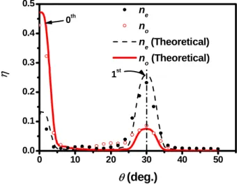
Next, a liquid-helium-cooled Si bolometer was employed to trace the angular distribution of the diffracted THz beam by the LC phase grating. In these experiments, the broadband THz pulse was filtered by the MHA (a 0.5 mm-thick aluminum plate perforated with circular holes arrayed in a triangular lattice of lattice constant s = 0.99 mm and the diameter of each hole, l = 0.56 mm) as a filter to yield a quasi-monochromatic wave centered at 0.3 THz with a line width of 0.03 THz [16]. 0 10 20 30 40 50 0.0 0.1 0.2 0.3 0.4 0.5 η 1st θ (deg.) ne no ne (Theoretical) no (Theoretical) 0th
Fig. 5. Diffraction efficiencies as a function of diffraction angle (θ) for the 0.3 THz-beam. The grating operated as a variable beam splitter for the 0th and 1st orders diffracted beams.
Figure 5 illustrated the diffracted intensity profiles of the 0.3 THz-beam polarized in the y-direction. The measured diffraction efficiencies for 0th and 1st orders were 0.43 and 0.08 for o-ray, 0.13 and 0.23 for e-o-ray, respectively. These were also in good agreement with the theoretical estimate, taking into account of the finite dimension of the grating and acceptance angle of the bolometer. The acceptance angle of ±3° associated with the detection area of the bolometer was considered and the result predicted by Eq. (1) adjusted accordingly.
A diffraction maximum was detected at θ = 30°, which corresponded to the 1st order diffracted beam that was predicted by the grating equation. As mentioned in the preceding paragraph, when the phase difference Δφ was close to 2π, most of the THz signal propagated in the direction of the 0th order diffraction if the refraction index of E7 was no. Experimentally, we found the diffraction efficiencies were 0.43 and 0.08 for the 0th and 1st orders diffracted beams, respectively. When the phase difference Δφ was close to π, the refractive index of E7 was ne and the THz wave mostly propagated as 1st order diffracted
beam. The diffraction efficiencies were 0.13 and 0.23 for the 0th and 1st orders diffracted beams, respectively. The grating thus served as a variable beam splitter. Rotating the magnetic field direction enabled the beam splitting ratio between the 0th and 1st orders diffracted beams
to be tuned from 4:1 to 1:2.
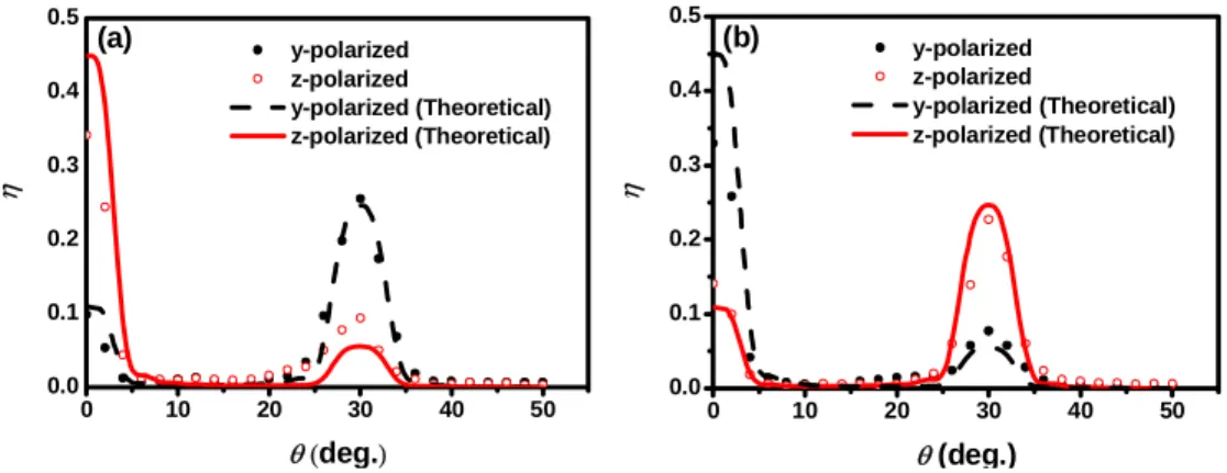
If the THz beam was linearly polarized in any other direction, the phase grating also showed the potential for operating as a switchable polarizing beam splitter. Figure 6 shows the experimental results measured using the same setup as described above as well as the theoretical curves. The polarization of the incident 0.3 THz-beam was set by rotating the wire-grid polarizer before the grating to an angle of 45° with respect to the y-direction while the magnetic field remained in the y-direction. The transmitted y-polarized THz beam propagated mostly as the 1st order diffracted beam, while the z-polarized THz wave mostly propagated as the 0th order diffracted beam. When the applied magnetic field was switched to that along the z-direction, the diffraction patterns of the above two polarized THz waves were interchanged.
0 10 20 30 40 50 0.0 0.1 0.2 0.3 0.4 0.5 η θ (deg.) y-polarized z-polarized y-polarized (Theoretical) z-polarized (Theoretical) (a) 0 10 20 30 40 50 0.0 0.1 0.2 0.3 0.4 0.5 η θ (deg.) y-polarized z-polarized y-polarized (Theoretical) z-polarized (Theoretical) (b)
Fig. 6. Polarization beam splitting using the LC phase grating. (a) Magnetic field was in the y-direction. (b) Magnetic field was in the z-y-direction.
4. Conclusions
In summary, a magnetically controlled tunable LC phase grating for manipulating the THz wave at room temperature was demonstrated. The waveform of the broadband THz wave was modified in the time-domain and the spectral transmittance could be varied in the frequency-domain. The splitting ratio of the diffracted THz-beam (0.3 THz) polarized in a direction perpendicular to that of the grooves of the grating could be tuned from 4:1 to 1:2. Additionally, when the THz wave was polarized in any other direction, this device had the potential to operate as a polarizing beam splitter.
Acknowledgments
This work was supported in part by the National Science Council grants NSC 95-2221-E-009-249, PPAEU-II and the ATU program of the Ministry of Education, Taiwan, ROC.