i
國
立
交
通
大
學
光電工程研究所
碩
士
論
文
電壓漸變式液晶透鏡於手持行動裝
置之成像系統與應用
Imaging Applications of spherical
Gradient-Driven Liquid-crystal Lenses for
Mobile Devices
研 究 生:陳禹辰
指導教授:謝漢萍 教授
黃乙白 副教授
ii
電壓漸變式液晶透鏡於手持行動裝
置之成像系統與應用
碩士研究生:陳禹辰 指導教授:謝漢萍教授
黃乙白副教授
國立交通大學 顯示科技研究所
摘要
在最近幾年的手機市場,照相變成一種基本功能,幾乎每支手機都是照相手 機,而且畫質已經漸漸追上一般數位相機。在一般相機中,光學變焦是非常炙手 可熱的一項功能。在傳統光學中,光學變焦依靠鏡組間的機械移動來改變其等效 焦長。由於空間上的限制,目前沒有光學變焦的手機鏡頭,所有手機鏡頭的變焦 都只是數位變焦。 液晶透鏡是一種可自我調變焦距的透鏡,因為其焦距可調,因此可用於小體 積的光學變焦。本研究提出一種電壓漸變式液晶透鏡,這種透鏡解決了傳統液晶 的兩大缺點—數十秒的聚焦時間與數十伏特(甚至近百伏特)的驅動電壓。電壓漸 變式液晶透鏡是一種內置電極液晶透鏡,其控制電極直接接觸液晶層。其關鍵技 術為,在控制透明電極之上鍍一層高電阻材料,這層材料可以有效地把能量留在 液晶層,讓能量不會浪費在其他地方。因為高電阻層的幫忙,電壓漸變式液晶透 鏡的驅動電壓只需要不到 4 伏特,而搭配本實驗室之前提出之過驅動方法,可以 有效地將聚焦時間縮短到 0.8 秒。 將電壓漸變式液晶透鏡搭配傳統的塑膠鏡頭組成一簡易式光學成像系統,此 成像系統印證了電壓漸變式液晶透鏡的實用性。相信假以時日,電壓漸變式液晶 透鏡可以成功應用在光學變焦系統之中。iii
Imaging Applications of spherical
Gradient-Driven Liquid-crystal Lenses for
Mobile Devices
Student: Yu-Chen Chen Advisor: Dr. Han-Ping D. Shieh
Dr. Yi-Pai Haung
Abstract
In mobile devices, camera has become a basic function today, almost every mobiles has a camera. In photography, optical zoom was eager for consumers nowadays. Optical zoom utilized mechanical movement of lens elements to change the focal length. Since the limit of space, there are no optical zoomable cameras in mobile devices.
Liquid Crystal lens is type of electrically-tunable focus lens. However, high operating voltage and slow focusing time are two of the major issues in the liquid crystal lens applications. Spherical Gradient Driven Liquid Crystal Lens (sGD-LC lens) was proposed to solve these two issues. A high-resistance layer was spin-coated above the patterned electrodes, which create a gradient distribution of electric field and preserved majority energy was applied. For a specification with 60m LC cell-gap and 2mm lens aperture, the operating voltage was reduced down to less than 4 volts for 5cm focal length, and the focusing time was dramatically improved to 0.8 seconds.
Combining with sGD-LC lens, an auto-focusing system for mobile lens application was realized in this thesis. These features made mobile devices employing LC lens feasible and practical, while LC optical zoom system is also realizable by appropriate optical design.
iv
誌謝
浪子回頭金不換,如果要我為這六年下個註解。 還記得六年前的現在正為了填寫志願而思考著,該要選擇擁有數十年歷史的大系, 還是剛創立一年的小系呢?最終的選擇是後者,單純覺得那應該會像個大家庭, 而直到現在我才知道,這是我生命中至今最重要的決定。一路走來,雖然走得跌 跌撞撞,但看著交大光電從無到有,從疏遠到親密。那是學生與老師一同努力的 結果,光電小系就像當年夢想中的大家庭。感謝六年來一起走過的光電系 97 級、 98 級、99 級。謝謝你、妳、與你們。謝謝妳,交大光電,我的母系。 我要非常感謝黃老師與謝老師,從大學做專題開始,到現在學生生涯暫時告一段 落。跟隨兩位老師的這四年,除了學習上的問題,老師也不吝於分享其他比學習 更重要的事情。在學習研究上,您們是我老師;在學習做人上,您們更是我老師。 我要特別感謝液晶組的成員們,凌嶢、博六、玉米、致維哥、該逼。一次次的開 會討論,一次次的黃光製程,我會特別懷念在奈米中心,那期待終有一天能撥雲 見日的日子。我也很開心有著一群實驗室的好夥伴,在這還是學生的最後兩年, 我們一起訂便當、一起打球。如果還有什麼遺憾,就是連續拿了好幾次的聯誼盃 亞軍吧。 最後是我的父母。謝謝你們包容這任性的孩子,容忍他從小就不好的成績與愛玩 的天性。你們是我最大的後盾。我要把這篇論文獻給你們。謝謝你們,我愛你們。v
Table of Contents
摘要 ... ii
Abstract ... iii
誌謝 ... iv
Figure Captions ... vii
List of Tables ... x
Chapter 1 ... 1
1.1 Imaging Optical System... 1
1.2.1 Tunable-Focus Lens ... 2
1.2.2 Liquid Crystal Lenses ... 3
1.3 Lens Head in Mobile Devices ... 5
1.3.1 Auto-Focusing ... 5
1.3.2 Optical Zoom ... 11
1.4 Motivation and Objectives of This Thesis ... 13
1.5 Organization of This Thesis ... 15
Chapter 2 ... 16
2.1 LC Material ... 16
2.2 Optical Properties of LC ... 16
2.3 LC Lens ... 17
2.4 Gradient-Driven Liquid Crystal lens (GD-LC lens) ... 21
2.4.1 Concept ... 21
2.4.2 Effective RC Circuit of GD-LC Lens ... 23
Chapter 3 ... 27
3.1 Fabrication Process ... 27
3.1.1 ITO Glass Substrates Cleaning ... 28
3.1.2 Lithography ... 29
vi
3.1.4 Sample Assembling... 32
3.2 Technical Challenges of Fabrication ... 33
3.2.1 Leakage of Electricity ... 34
3.2.2 Symmetric of Pattern ... 35
3.2.3 Re-Dissolved of Hi-R Layer... 36
Chapter 4 ... 37
4.1 Properties of sGD-LC Lens... 37
4.1.1 Experiment Setup... 38
4.1.2 Convex Mode and Concave Mode ... 40
4.2 Imaging System ... 41
4.2.1 Over-Drive Method ... 41
4.2.2 Imaging System Setup ... 43
4.3 Auto-Focusing ... 44
4.4 Power Consumption of AF Imaging system ... 46
Chapter 5 ... 48
5.1 MTF of AF Imaging System ... 49
5.2 LC Zoom Lens ... 51
5.2.1 Basic Theorem of Optical Zoom System ... 51
5.2.2 Simulation and System Design ... 52
5.3 Image Defects of AF Imaging System ... 54
5.3.1 Leakage of Ordinary Ray. ... 55
5.3.2 Tilt of Object Plane ... 57
5.4 Summary ... 59
Chapter 6 ... 59
6.1 Conclusion ... 59
6.2 Future Work ... 63
6.2.1 Resistance Controlling of Hi-R Layer ... 63
6.2.2 Improvement of Zoom Ratio ... 64
vii
Figure Captions
Figure 1-1 First LC lens of world proposed by Prof. Susumu Sato……….….3
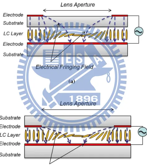
Figure 1-2 Two of the most general homogeneous LC Lenses, (a) external electrodes, and (b) internal electrodes utilizing electrical fringe field of the electrodes to generate a gradient variation in phase retardation...4
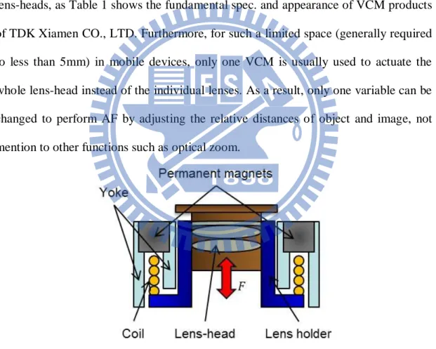
Figure 1-3 Structure of conventional VCM actuator...6
Figure 1-4 Focusing mechanism of VCM approach...7
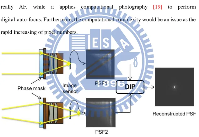
Figure 1-5 Principle of EDoF method...8
Figure 1-6 (a)The liquid lens employs the oil-water surface and electrically control the surface shape. (b) The liquid lens mechanically controlled the membrane shape to focus the light...9
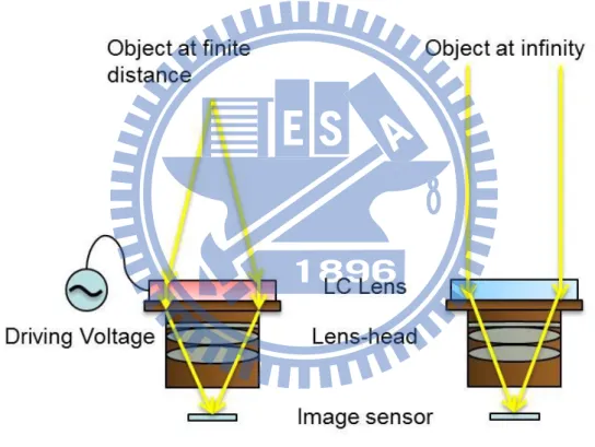
Figure 1-7 Mechanism of LC lens used for AF function in mobile device...10
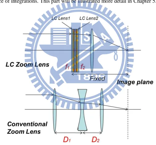
Figure 1-8 Structure of LC zoom lens and conventional zoom lens...12
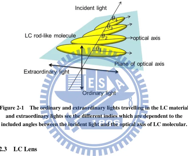
Figure 2-1 The ordinary and extraordinary lights travelling in the LC material and extraordinary lights see the different indies which are dependent to the included angles between the incident light and the optical axis of LC molecular...17
Figure 2-2 Simplest structure of LC lens……….………...………18
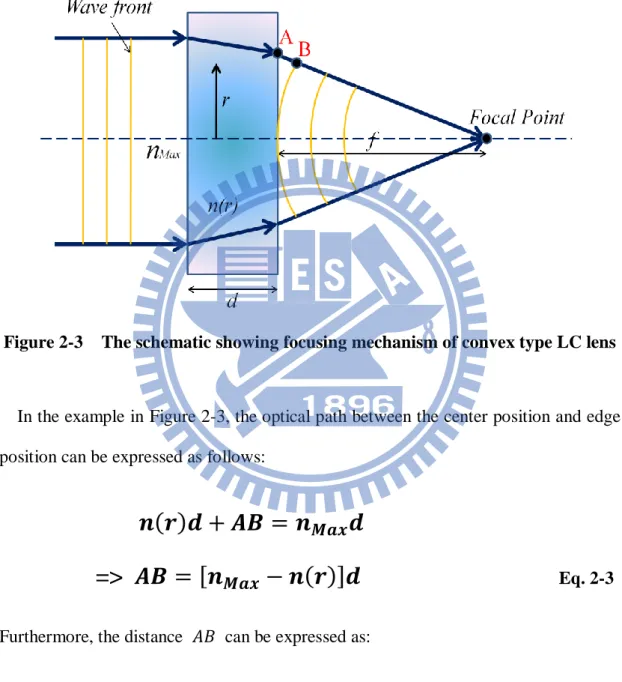
Figure 2-3 The schematic showing focusing mechanism of convex type LC lens.….19 Figure 2-4 Ideal parabolic curve function of and radius of lens aperture……..21
Figure 2-5 The testing device of LC cell with high resistance layer connected by two controlling electrodes...22 Figure 2-6 Results of interference pattern of the testing device driven by different operating voltages, (a)ΔV=3 Vrms, (b)ΔV=3.6 Vrms, and (c) ΔV=5Vrms. The LC cell was design by 60μm cell gap driven by the two controlling electrodes with 2mm
viii
separation...23
Figure 2-7 Configuration of GD-LC Lens, includes side view and section view. The structure with 2mm lens aperture and 60um anti-parallel LC cell gap was constructed by combining triple internal electrodes with the high resistance layer...24
Figure 2-8 The R-C circuit utilized to model GD-LC lens...25
Figure 2-9 The ITO pattern of cylindrical and spherical GD-LC lens……..….……..26
Figure 3-1 Flow chart of fabrication process………..………..………..28
Figure 3-2 Flow chart of cleaning process………..……..……..29
Figure 3-3 Flow chart of lithography process………..………...30
Figure 3-4 Flow chart of digging structure………..…..…….31
Figure 3-5 Section diagram of GD-LC lens………...…...……..32
Figure 3-6 Flow chart of assembling sample….………..…...…33
Figure 3-7 The un-overlapped structure………..….………..34
Figure 3-8 Interference patterns of different driving frequency depends on (a) 10Hz, (b) 1000Hz...35
Figure 3-9 Top view and the overlap area of this design………...…………36
Figure 3-10 (a) Side View of sGD-LC lens……….………36
Figure 4-1 Schematic of measurement system……….……..39
Figure 4-2 Focusing profiles of sGD-LC lens when focal length are (a)5cm, (b)7cm, (c)15cm, (d)20cm, and (e)25cm...39
Figure 4-3 The relation between voltage-frequency pairs and focal length...39
Figure 4-4 Phase retardation patterns of (a) convex and (b) concave modes by difference operating of GD-LC lens...41
ix
Figure 4-6 Real waveform of OD-method...42
Figure 4-7 The focusing process of GD-LC Lens and the conventional LC lens...43
Figure 4-8 Configuration of AF system with sGD-LC lens...44
Figure 4-9 The AF result of three distance at (a)7cm, (b)15cm, and (c)90cm...46
Figure 4-10 Power consumption of sGD-LC lens respect to focal length…..……….47
Figure 4-11 Power and volume comparison of sGD-LC lens and VCM……….……48
Figure 5-1 Measurement setup for MTF……….………49
Figure 5-2 Point spread function of the AFsystem in (a) off-state and (b) when sGD-LC lens was driven for 15cm focal length...50
Figure 5-3 The calculated MTF of the AF system with sGD-LC lens...50
Figure 5-4 Three main compositions of zoom lens……….52
Figure 5-5 Schematic diagram of LC zoom lens……….……54
Figure 5-6 Variation of lens power, K, changed by LC lens power, K1 and K2...54
Figure 5-7 Fringing patterns of (a) inferior and (b) superior sGD-LC lenses...55
Figure 5-8 Comparison of (a) no o-ray leakage at 90cm, (b) o-ray leakage at 6cm. The right-bottom corner of (b) exist a little o-ray (unfocussed ray)...56
Figure 5-9 O-ray leakage comparison of (a) inferior (b) superior sGD-LC lens…...57
Figure 5-10 The ideal and real object plane, while the real object plane is tilt respect to optical axis...58
Figure 6-1 The dramatically improvement of driving voltage and focusing time with GD-LC lens combined with Over-Drive method...61
Figure 6-2 The variation of lens power, K, when D12= 2cm...65
x
List of Tables
Table 1 The spec. list of conventional VCM...7
Table 2 Comparison of AF technologies...11
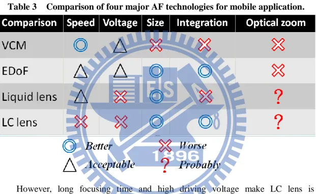
Table 3 Comparison of four major AF technologies for mobile application...14
Table 4 Comparison of focusing time and corresponding operating voltage. The result shows GD-LC Lens significantly improved the focusing time and only driven by low operating voltage...43
Table 5 Comparisons of single tunable lenses...62
Table 6 Comparison of the AF solutions after the improvements of GD-LC lens...62
Table 7 Comparison of organic material and inorganic material………..…..64
1
Chapter 1
Introduction
1.1 Imaging Optical System
Lenses are key elements of optical systems. Most conventional lenses are made of glass, polymer, or other transparent solid materials, which have a fixed focal length.
Aberrations are departures of the performance of an optical system from the predictions of paraxial optics [1]. Aberrations can be divided to two part,
monochromatic aberrations and chromatic aberration [2]. Monochromatic aberrations
can mainly be classified into spherical aberrations, astigmatism, coma, curvature of field, and distortion, which are known as Seidel aberrations. Chromatic aberration was caused by different effective refractive index of different wavelength of light. Both of them affect optical quality massively. The optical quality of a single lens is terrible since one lens has merely three variables to correct the aberrations. An optical system assembled by several different forms of lenses was needed for compensate and correct these aberrations.
An imaging optical system with a fixed effective focal length was called prime lens. To change the effective focal length of optical system continuously, a zoom lens which is a mechanical assembly of lens elements with the ability to vary its effective focal length has been developed. There are many possible designs for zoom lenses, the most complex ones having upwards of thirty individual lens elements and multiple
2
moving parts. A simple scheme for a zoom lens divides the assembly into three parts: Variator and erector and compensator [3]. Numbers of lens components and
movement of the variator and compensator make the zoom lens bulky and heavy. In mobile devices, all the components were limited by the volume. Since zoom lens is bulky and heavy, applying zoom lens system into mobile devices is unfeasible.
1.2.1 Tunable-Focus Lens
Conventional lens has superior optical performance and wildly use in many optical applications. However, the focal length of conventional lens is fixed, and focal-tunable lens are usually bulky and heavy. Focus-tunable lens with small volume and slight weight was eager for. Single tunable lens has been already existed in the nature, for example, human eyes. The human eyes tuned focus by shape-changed, as controlled by the muscles in the eye. Some technologies use similar concept of human eye, such as liquid lenses [4-5], or microfluidics lenses [6-7].
Polymer and liquid crystal (LC) are also the materials for single tunable lens. Instead of shape changing, stressed polymers and LC are refractive index changing. For current applications, LC is wildly utilized for Spatial Light Modulators (SLMs)[8-9],
the known one is Liquid Crystal Displays (LCDs) [10].The most important property of
LC molecular is that the refractive index is electrical controllable. Its stability also favors the industrial fabrications. Therefore, LCs is a unique and suitable material for single tunable lenses.
3
1.2.2 Liquid Crystal Lenses
Liquid crystal lens was first proposed by Prof. Susumu Sato in 1979[11]. A
convex and concave glass lens with surface transparent substrate was assembled to another glass substrate, and liquid crystal molecular was injected into the cavity, as shown in Figure 1-1. The LC lens was classified to inhomogeneous LC alignment and homogeneous LC alignment by Prof. Shin-Tson Wu[12-13]. The inhomogeneous LC
alignment type has a serious issue, resulting in scattered light because the LC molecular director suffers a non-uniform initial anchoring force. Therefore, only the homogeneous LC alignment type will be introduced in the following paragraphs.
Figure 1-1 First LC lens of world proposed by Prof. Susumu Sato
The simplest structure of LC Lenses is utilizing the electrical fringe field to control the orientation of LC. This structure is typically constructed by two flat substrates clipping a homogeneous LC layer. The ITO electrodes on the substrates can be patterned to yield the fringing field. In this kind of homogeneous LC Lens, the patterns of electrodes and electrical control are critical for yielding the desired phase retardation on uniform LC layer. Two of the homogeneous LC Lenses are shown in Figure 1-2 (a) and (b), structures with external and internal electrodes, both of which utilize the fringe field of the electrodes to control the phase retardation of the LC layer. The electrodes
4
are typically constructed of ITO. The difference of these two structures is the insertion of high K material (i.e. the substrate) between two ITO layers, which the function is to smooth electric field communicated to the LC layer. This kind of structure is effective, simple, and also easy for realizing spherical and cylindrical LC Lenses. In order to have the benefit of simple structure and more flexible for applications, our studies focused on this kind of LC lenses.
(a)
(b)
Figure 1-2 Two of the most general homogeneous LC Lenses, (a) external electrodes, and (b) internal electrodes utilizing electrical fringe field of the
5
1.3 Lens Head in Mobile Devices
Mobile devices has become the necessary produces for daily life’s usage in recent years, especially when communication technology is growing up fast. Lens-heads are key components in the devices, such as cell-phones, laptops, and tablet PCs. When performing functions of photography, phantom identification, computer vision, and image communications through these devices, lens-heads always play an important role to deal with the basic function of imaging. For this essential function, image quality of the lens-heads is improved to satisfy the rapid growing-up pixel numbers. Furthermore, optical designers also face the challenge to minimize the thickness of lens modules as these devices are required to be slimmer and slimmer. Not only the simple imaging function, but also technologies of auto-focusing (AF) and optical-zoom are also diligent directions for improving the image quality. In this part, four technologies of the auto-focusing will be illustrated.
1.3.1 Auto-Focusing
Voice Coil Motor (VCM)
Voice Coil Motor (VCM) is one of the approaches to perform AF in mobile devices[14-15]. The principle of VCM is the same as a loudspeaker exciting its voice
coil with a controlled current to vibrate its diaphragm. In the application of AF, the VCM actuator consists of two main parts, the fixed permanent magnets and the moving lens-holder coiled coil, as shown in Figure 1-3. To actuate a lens-head, the positive and negative Lorentz force can be yielded by different direction of driven currents. The equation illustrates the relation following:
6
(1-1)
where , , , , and Lorentz force, the number of coil, the length of coil vertical to direction of magnetic field, driven current, and magnetic flux density respectively. Moving the lens-head, VCM method can shift the image plane to the position of image sensor for focusing objects at a finite distance, as shown in Figure 1-4. Therefore, it is an effective approach to perform AF in such a limited space of mobile devices, and one of the mainstreams for current solutions for AF. However, the size of VCMs is generally larger than that of lens-heads for embedding the lens-heads, as Table 1 shows the fundamental spec. and appearance of VCM products of TDK Xiamen CO., LTD. Furthermore, for such a limited space (generally required to less than 5mm) in mobile devices, only one VCM is usually used to actuate the whole lens-head instead of the individual lenses. As a result, only one variable can be changed to perform AF by adjusting the relative distances of object and image, not mention to other functions such as optical zoom.
7
Figure 1-4 Focusing mechanism of VCM approach.
8
Extended Depth-of-field (EDoF)
Extended Depth-of-field (EDoF) is a novel computational imaging approach for extending the Depth-of-field of fixed-focus mobile lens [16-18]. Utilizing a phase
mask combined with lens-head, the system can generate similar Point Spreading Functions (PSFs) from object points within a wide range. By digital image processing (DIP), the object points can be reconstructed and imaged clearly, as the schematic shown in Figure 1-5. The PSFs captured from different distances are similar which means the field exhibiting clear images can be extended. However, EDoF method is not really AF, while it applies computational photography [19] to perform
digital-auto-focus. Furthermore, the computational complexity would be an issue as the rapid increasing of pixel numbers.
Figure 1-5 Principle of EDoF method.
Liquid lenses
Liquid lens is a kind of shape-changed lens which is used one or more fluids to generate a lens-shape refractive index. General liquid lenses are constructed by an interface between two different materials. These materials can be air-to-water or two
9
different liquid materials (ex: water-to-oil)[20-21]. Electrically or mechanically control
the shape of the interface; we can vary the lens power, and shown in Figure 1-6(a) and (b). The issues of this technology are the environmental limitations, such as gravity or low feasible range of temperature.
Figure 1-6 (a)The liquid lens employs the oil-water surface and electrically control the surface shape. (b) The liquid lens mechanically controlled the
membrane shape to focus the light.
LC Lenses
As Chapter 1.2.2 mentioned, the LC lens has unique properties such as electrically tunable focal length. Since there are no moving mechanical parts, the LC lens can be smaller and lighter than conventional tunable glass lenses. In mobile devices, the LC
10
lens can directly combine with mobile lens-module in front of the lens-head, and easily perform AF function by driving appropriate voltage to focus objects at different distances. For example, as illustrated in Figure 1-7, a conventional lens-head focuses object at infinite distance, and utilizes the LC lens applied by driving voltage to increase lens power for imaging the objects at finite distance. Rays from the object point can be parallel incident to the lens-head through the LC lens. There is no difference for the lens-head to image the object at infinity and finite distance, if the LC lens can image the finite one well. This imaging structure was also used in this study.
Figure 1-7 Mechanism of LC lens used for AF function in mobile device.
For a short summary of this section, as Table 2 shows. Since VCM has fastest focusing time and best optical quality, it is generally utilized in mobile devices now, but the volume is too big and required accuracy integration. EDoF is intrinsically DIP, so the focusing time depends on the calculation capability of driving IC. Since EDoF
11
needs only one additional phase mask, so the volume is small and low difficulty of integration. Liquid lens and LC lens are similar type of AF technology. Each of them has their own advantages and disadvantages. In this section, we do not conclude which one is better. While no matter liquid lens and LC lens, slow focusing time and high driving voltage are major issues which are needed to be solved.
Table 2 Comparison of AF technologies.
1.3.2 Optical Zoom
Optical zoom is usually performed in imaging systems to zoom the captured images in and out. By changing the effective focal length (EFL) of the imaging system, the zoom ratio can be adjusted. However, zoom lens is usually a bulky system due to the requirement of spacing for moving the lens groups. This requirement is more sensitive in mobile devices, the space and tolerance is much critical for adding this function. Therefore, digital zoom is wildly adopted for magnifying images, even though it is equals to crop and enlarge the cropped image.
In theoretical, LC lenses have the ability to change the focal length electrically without the mechanical moving. That means the optical system embedded LC Lenses
12
can change its EFL to achieving optical zoom within a constant thickness. In other words, LC lens is distinguished from the other methods which not only can perform AF but also has the potential for optical zoom simultaneously within the small spacing. The simplest approach is to utilize double LC lenses to simulate the variator and compensator of conventional zoom lenses respectively, as Figure 1-8 shows. By adjusting the focal lengths, f1 and f2, of each LC lens. The EFL of the system are varied
for corresponding zoom ratio. Rather than modifying the spacing, D1 and D2, the LC
zoom lens can maintain the minimized total thickness of the system and increase tolerance of integrations. This part will be illustrated more detail in Chapter 5..
13
1.4 Motivation and Objectives of This Thesis
In recent years, mobile devices with camera lenses are more and more popular. It is because, for current applications, the camera lenses are not only used for taking pictures but also for communicating with environments and other people. To yield high image quality and acceptance for consumers, the trends of the camera modules including high resolution, miniature size, high optical throughput, and additional functions, such as AF and optical zoom are achieving by optical designers. However, for the functions of AF and optical zoom which conventionally require mechanical movement are not easy to be realized in limited size of mobile devices. Currently, four mainstreams could achieve AF, they are VCM, EDoF, Liquid lens and LC lens. VCM is a mechanically moveable motor, which adjust position of lens heads to perform AF and can provide superior image quality, but it takes a bulky volume and suffers from integration issues. EDoF utilizes wavefront coding technology. By digital image process (DIP), a computational focusing can be restored. However, this computational method is not real AF. Liquid lens is a focal-electrically tunable type lens which utilizes electric field to control curvature of liquid surface. It could be light and compact, but the complex structure and high driving voltage make liquid lens not easy to be employed in many applications. LC lens is a new type of single tunable lens which has been wildly used in different optical applications. The electrically tunable focal-length without any mechanical movement make LC lens lighter and compacter than conventional glass lens.
Table 3 compared the advantages and disadvantages of these four technologies. The last column plays the most important role of the column. In spite of VCM is the most widely used technology and owned the best image quality nowadays, it cannot
14
achieve optical zoom since the limited space of mobiles and the volume of VCM is too big. While EDoF performed digital AF for a wild field to obtain the clear images from objects at different distance, but this technology also cannot change EFL of optical systems. Obviously EDoF is not the options of optical zoom. The liquid lens and the LC lens are both tunable-focus lens. Since liquid lens required more precision and accuracy of integration, so LC lens is the best choice to achieve optical zoom of mobile devices.
Table 3 Comparison of four major AF technologies for mobile application.
However, long focusing time and high driving voltage make LC lens is impracticable for commercial products. So naturally, the major technical challenge of LC zoom lens is to reduce the unfeasible driving voltage and shorten the impractical focusing time. While focusing time is the most important issue since no one can wait ten more seconds to take a picture. For commercial use, focusing time should be controlled less than 1sec, and the driving voltage also needed to be controlled in less than 10 Volts since high driving voltage waste unnecessary power. So our target is to exhibit a kind of LC lens which driving less than 10Volts and focusing less than 1second.
15
1.5 Organization of This Thesis
This thesis is organized as follows: In chapter 2, some basic principles and theories of LC lens will be explained, and then Gradient-Driven Liquid Crystal lens (GD-LC lens) will be introduced. In chapter 3, the fabrication process and some technical challenge of fabrication will be clearly presented this part include how to design a spherical GD-LC lens pattern. In chapter 4, the ultra-fast auto-focusing experiment will be illustrated. In chapter 5, some analysis of optical properties and the simulation results of optical zoom will be demonstrated. Finally, chapter 6 will give a short conclusion and future works.
16
Chapter 2
Basic Principles and Theories of LC Lens
2.1 LC Material
A matter has three classical states which are solid crystal, liquid, and gas. Liquid crystal (LC) is a state between liquid and solid crystal, it has both characteristics of solid crystal and liquid. For example, LC may flow like a liquid, but may be oriented like a crystal. LC can be classified into five types by optical properties: nematic phase, smetic phase, chiral phase, blue phase, and discotic phase[22]. The nematic LC was
used in this thesis.
2.2 Optical Properties of LC
LC is a birefringence material. This property causes the incident light with different polarizations meet different refractive index. For analyzing the difference of index, the light can be decomposed into two perpendicular polarized directions, one of which is parallel to the optical axis of the material and the other one is perpendicular to the plane of optical axis. The parallel one which is named ordinary light sees all the same index no matter how the included angle between the incident light and the optical axis, as shown in Figure 2-1. On the other hand, the polarization which is perpendicular to the plane of optical axis, named extraordinary light, sees the refractive index which is direction dependent. Although, the index would be varied by the included angles between the incident light and the optical axis, the effective index can be calculated by
17
Eq. 2-1
where and are the extraordinary and ordinary refractive indies respectively. is the included angles between the incident light and the optical axis, also was shown in Figure 2-1.
Figure 2-1 The ordinary and extraordinary lights travelling in the LC material and extraordinary lights see the different indies which are dependent to the included angles between the incident light and the optical axis of LC molecular.
2.3 LC Lens
Liquid crystal lens, a focal tunable optical lens made by Liquid Crystal. The simplest structure of LC lens was shown in Figure 2-2. The Liquid Crystal layer sandwiched by two ITO glass substrates. When LC lens was in off state, all LC molecular was parallel to substrate and has a uniform refractive index which is ne.
When LC lens was turned on, marginal LC molecular was effect by perpendicular electric field and turned 90 degree. The effective refractive index of central area was same as off state which is ne, but no in marginal area. A gradient distribution of
18
refractive index was obtained. Since the speed of light is depends on refractive index, the phase retardation is occurred, and the LC lens was focusing.
Figure 2-2 Simplest structure of LC lens
Effective focal length
Nematic LC material has a birefringence property including ordinary refractive index and extraordinary refractive index. When an electric field is applied to the LC cell, the LC is reoriented and its tilt angle is changed. The director is rotated and an effective refractive index has to be considered which is dependent on the degree of the LC’s tilt angle. The effective refractive index can be calculated using the following equation [23]:
Eq. 2-2
where the denotes the angle between the polarization of incident light and LC optical axis, and the and denote the refractive index for the ordinary light beam and the extraordinary light beam.
19
To derive the effective focal length in LC lens, incident polarized light is assumed to be planar wavefront. Since every point in the same wavefront should pass the same optical path, this incident planar wavefront will bend into a spherical wavefront. For example, Figure 2-3 shows how a convex type LC lens focuses light.
Figure 2-3 The schematic showing focusing mechanism of convex type LC lens
In the example in Figure 2-3, the optical path between the center position and edge position can be expressed as follows:
=>
Eq. 2-3
Furthermore, the distance can be expressed as:
Eq. 2-4
where
20
Eq. 2-5
Because the effective focal length, f, is much higher than the lens radius value, r, the Fresnel’ approximation is used as follows [24]:
Eq. 2-6
Through transposing of Eq.2-6, another representation of can be expressed as shown in Eq.2-7.
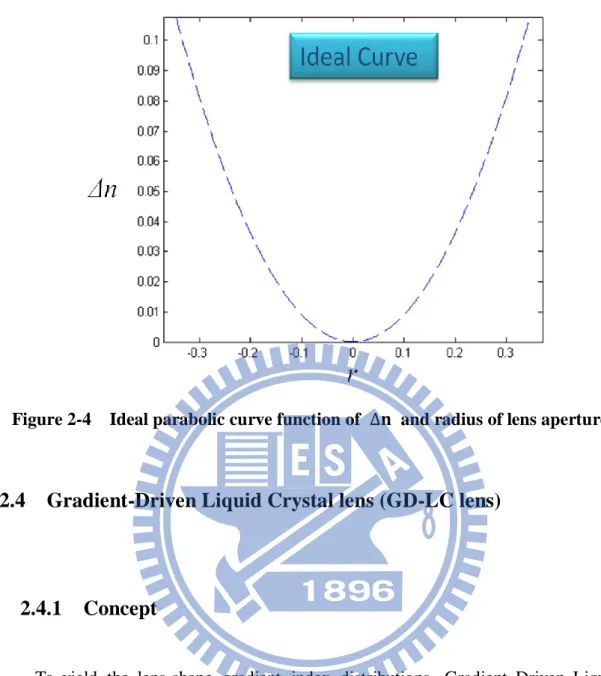
Eq. 2-7 Ideally, every part of the lens should fit the same focal point or aberrations will be observed. According to Eq.2-7, shall be a parabolic function of , as shown in Figure 2-4.
21
Figure 2-4 Ideal parabolic curve function of and radius of lens aperture
2.4 Gradient-Driven Liquid Crystal lens (GD-LC lens)
2.4.1 Concept
To yield the lens-shape gradient index distributions, Gradient Driven Liquid Crystal Lens (GD-LC Lens) was proposed to intrinsically solve the issue of high driving voltage and slow focusing. GD-LC Lens utilized a high resistance layer (high R layer) to be the internal continuous-distributed electrode to achieve low operating voltage and improve the focusing time simultaneously. The high R layer, which was spin coated on a substrate to connect two controlling electrodes. This structure generated gradient electrical distribution when applied two different operating voltages on each controlling electrode. Two of the controlling electrodes were separated by 2mm, as Figure 2-5 shows. In the investigation of spatial phase retardation, different
22
operating voltages driven at 1 kHz were applied to the right side of controlling electrode. The left side electrode was grounded to yield an initial potential difference (ΔV) between two electrodes. Different interference pattern were observed by changing operating voltage. At V=3Vrms, the interference pattern was denser on the right side, as shown in Figure 2-6 (a). This pattern indicates a convex lens can be achieved by symmetrically combining two identical structures with the same operating voltage. On the other hand, at V=5Vrms, the interference pattern was denser on the right side, as shown in Figure 2-6 (c). A concave lens also can be realized by the driving. Figure 2-6(b) shows linear phase retardation between two electrodes which is unsuitable for lens applications.
Figure 2-5 The testing device of LC cell with high resistance layer connected by two controlling electrodes.
23
(a) (b) (c)
Figure 2-6 Results of interference pattern of the testing device driven by different operating voltages, (a)ΔV=3 Vrms, (b)ΔV=3.6 Vrms, and (c) ΔV=5Vrms. The LC cell was design by 60μm cell gap driven by the two controlling electrodes
with 2mm separation.
2.4.2 Effective RC Circuit of GD-LC Lens
According to the testing results, the structure of GD-LC Lens was constructed by combining triple internal electrodes with the high resistance layer. Three controlling electrodes included two marginal controlling electrodes and a central controlling electrode. By applying the voltage on the marginal electrodes and making the central electrode grounded, GD-LC Lens was driven in convex mode. Oppositely, concave mode can be achieved by the central controlling voltage with two grounded marginal electrodes. The arbitrary electric field gradient profile was achieved by adjusting driving voltages. The structure is shown as Figure 2-7.
24
Figure 2-7 Configuration of GD-LC Lens, includes side view and section view. The structure with 2mm lens aperture and 60um anti-parallel LC cell gap was
constructed by combining triple internal electrodes with the high resistance layer.
A similar concept, LC lens with Modal Control [25], was proposed by A. F.
Naumov et al. In the research, a high resistance layer was utilized as the control electrode, and the thin LC layer was used to create a gradient electrical field. However, the numerical aperture (NA) was relatively low due to the controlling approach and the thin LC layer. This situation limited the applications in cameras which may require short focal length and large F/# to perform AF for near object and have higher optical throughput.
An R-C circuit can be used to model this structure, as show in Figure 2-8. From the circuit, following principles could be observed.
25
GD-LC lens can be voltage and frequency driving.
The resistance of the high R layer should be control in a proper range. If the resistance is chosen too low. The resistance from the hetero junction will occupied large ratio of applied voltage. On the other hand, as the resistance of the high R layer is too large, only a small ratio of current can achieve the center area if V1 is higher than V0. These two situations all result in no phase
retardation in the central area.
Extremely high frequency operation will result in smaller capacitance impedance. As a result, there is also small ratio of current pass through the high R layer to yield phase retardation.
Figure 2-8 The R-C circuit utilized to model GD-LC lens.
GD-LC lens with cylindrical structure has been developed. However, imaging optics should use spherical structure rather than cylindrical structure. Therefore, spherical GD-LC lens was proposed to apply in imaging optics. The ITO pattern was shown in Figure 2-9. Chapter 3 will illustrate how to fabricate a sGD-LC lens sample.
26
27
Chapter 3
Fabrication Process of sGD-LC Lens
In the first part of this chapter, the fabrication process of sGD-LC lens will be reported step by step. The process includes ITO glass substrates cleaning, lithography, thin film coating, and sample assembling.
In the second part of this chapter, some issues of fabrication process will be discussed, which includes how to design the spherical pattern.
3.1 Fabrication Process
The basic fabrication process is as shown in Figure 3-1. In the beginning of process, the ITO glass substrate needs to be cut into adequate size. Second, the ITO glass substrates should be cleaned since any small particle will cause fatal defect. Third is the lithography processes including multi-layer structure which contain photomask designing, spin coating of positive photoresist, UV light exposing and wet etching. Fourth, a high resistance material should be spin coated above the patterned ITO. Finally, the glass substrates, spacer, LC (E7) will be assembled as a complete sGD-LC sample.
28
Figure 3-1 Flow chart of fabrication process
3.1.1 ITO Glass Substrates Cleaning
A sGD-LC lens sample must be fabricated in clean room. While the first step that is troublesome, so cleaning ITO glass substrates should be an important thing. The purpose of cleaning is to eliminate small particles and chemical compositions above the surface. Figure 3-2 shows the flow chart of glass cleaning. A method of industrial was adopted. First of all, KG, a detergent from Yokohama Chemical Co. was diluted to de-ionized (DI) water, the ratio of KG and DI water was 1:100. Dipping the glass substrate into KG solution and oscillate 30 minutes. The purpose of this step is to remove greasy dirt and chemical compounds. Second, flushing glass substrates 5minutes with DI water, the step is for washout KG since KG is hard to clean. Third, dipping glass substrates into Acetone and oscillate 30minutes for organic compounds and KG cleaning. Fourth, pouring DI water and oscillate another 30miuntes for Acetone eliminating. Finally, the heater is used to evaporate the remaining water.
29
Figure 3-2 Flow chart of cleaning process
3.1.2 Lithography
We have already obtained a totally clean ITO glass substrate. Lithography, a process of fabricate ITO pattern what we want will be introduced. Since GD-LC lens needs jump structure in the center, the multi-layer structure must be utilize, this part will be discussed later. The flow chart of lithography is show in Figure 3-3 First, the spin coater was used to generate the uniform and thin photoresist layer on the surface of the cleaned glass substrate, while the spin speed is 1000rpm/15seconds for pre-spin and 2500rpm/25seconds for adequate thick of photoresist. A photoresist acts similarly to the sensitizer of a film in a camera since it could optically transfer the patterns of the layout from the photomask. A 90seconds soft baked should be taken, this step is for strengthen coated photoresist. Second, the UV light beam strokes the photomask which has been well-designed patterns and reacts with the chemical component of the photoresist. Third, the chemical reacted photoresist can be stripped off and remains
30
the no chemical reacted parts. Therefore, our desired patterns are generated on the photoresist after the exposures photoresist is developed. Further, the left photoresist is like a protective layer to its cover ITO part. Therefore, HCl is used to etch the ITO layer which has no photoresist covered part. Finally, stripping the left photoresist and our designed ITO pattern is generated.
Figure 3-3 Flow chart of lithography process
A central electrode is needed for concave mode of GD-LC lens, so the jump structure should be used for central electrode. Silicon Nitride (SiNx) was chosen for the insulation layer. The fabrication process of insulation layer and 2nd ITO layer are same as 1st ITO etching, so we skip the detail processes of insulation layer and 2nd ITO layer. The flow chart of these two additional layers is shown in Figure 3-4. Finally, the process of lithography was ended after etching these three layers.
31
Figure 3-4 Flow chart of digging structure
3.1.3 Thin Film Coating
Three different materials were needed to spin above the ITO glass substrate. First is photoresist which has been mention in Chapter 3.1.2. The second one is high-resistance (Hi-R) material which is the key element of GD-LC lens. The last one is polyimide which is used for alignment layer of LC.
Spin coating is a procedure used to apply uniform thin films to flat substrates. In short, an excess amount of a solution is placed on the substrate, which is then rotated at high speed in order to spread the fluid by centrifugal force.
Rotation is continued while the fluid spins off the edges of the substrate, until the desired thickness of the film is achieved. The higher angular speed of spinning obtains the thinner the film. The thickness of the film depends on the concentration of the solution and the solvent.
Hi-R layer is the most important part of sGD-LC lens. In this thesis, Clevious-P from Baytron was chosen to be the Hi-R layer. The spin speed of Hi-R layer is
32
4000rpm/30seconds to generate a 30nm thickness of Hi-R layer, the thickness was already measured by AFM. If the resistance is too low, Hi-R layer is like a conducting layer. Oppositely, if the resistance is too high, the driving voltage will increase. The resistance and driving voltage is a tradeoff, in our experiment, the appropriate value of surface resistance was chosen as ~1MΩ/□. Polyimide as an alignment layer was coated after Hi-R layer coated. Both of these two films need heating. For Hi-R layer, the function of heating is to dry it, the hot plate was set as 120℃ for 1hour. The requirement of heating for alignment layer is to harden the thin film. While the Hi-R layer is an organic material, high heating temperature should not be used. The hot plate was set as 150℃ 1.5 hour to prevent the damage of Hi-R layer. The section diagram of all thin films and substrates was shown in Figure 3-5.
Figure 3-5 Section diagram of GD-LC lens
3.1.4 Sample Assembling
The well-spin glass substrates could be assembled to GD-LC lens samples. The flow chart of the assembly process is shown in Figure 3-6. First, the roller made by woolen is used to rub the coated PI and give an arrange direction of LC. An
33
anti-parallel rubbing direction was taken for two glass substrates. Second, the spacers are placed on the substrate to support an appropriate cell gap. Furthermore, the glue is used to fix and seal one side of the LC cell for LC injecting. Third, drip the LC (E7) onto the chink of two glass substrate, the LC will drill into the gap automatically since the capillarity. Then, the UV glue is used to seal all the seams of the LC cell completely in order to prevent the LC material contact with the air. We suggest spread additional glue for ensure separation of LC and air. Finally, soldering the wires with the pattern on substrate, the LC lens is accomplished.
Figure 3-6 Flow chart of assembling sample
3.2 Technical Challenges of Fabrication
In this part, three problems which we have faced and have been solved will be illustrated. Although these problems disturbed us a while, but we learn a lot because of these problems. They are leakage of electricity, symmetric of pattern, and
34 re-dissolved of Hi-R layer
3.2.1 Leakage of Electricity
Chapter 3.1.2 explained how lithography working. The insulator SiNx was sputtered above 1st ITO layer. However, the dense of sputter coating is not high enough to insulate two ITO layer. Although chemical vapor deposition (CVD) could achieve high dense and insulate two ITO layer, but Hi-R layer which is organic compound is unable to accept high temperature. An un-overlapped structure was proposed to prevent the leakage of electricity, the pattern was shown in Figure 3-7. This design is useful for avoid leakage of electricity, however, the central connected ITO wire effected fringing field seriously, as shown in Figure 3-8 (a) and (b). The sample can just operate in low frequency (less than 60Hz) since the controlling modal in Chapter 2.4, but both the optical quality and power were still unusable.
35
Figure 3-8 Interference patterns of different driving frequency depends on (a) 10Hz, (b) 1000Hz.
According to the following results, the overlap of marginal and central electrodes was hard to avoid. Eliminating the overlap has become the most important thing. A pattern with very less overlap was designed. This pattern was not only solved the leakage but also improved the image quality, which will be illustrated in next section.
3.2.2 Symmetric of Pattern
For eliminate the effect of central connected ITO wire. A symmetric pattern was designed, as shown in Figure 3-9. The pattern has a tiny overlap area, since the small overlap area will not induce leakage of electricity. The maximum driving frequency of this design is much higher than 3.2.1 shows. Figure 3-10 (a) shows the side view of controlling electrodes of sGD-LC lens. The improvement of this design was illustrated in Figure 3-10 (b). The smooth and circular fringing pattern indicates this design is effective. A small defect of the pattern is diving frequency. When driving frequency is large than 50000 (Hz), the connected wire will influence fringing pattern. However, since the working frequency of GD-LC lens is between 100 to 10000Hz, so the variation of high frequency is unimportant.
36
Figure 3-9 Top view and the overlap area of this design
Figure 3-10 (a) Side View of sGD-LC lens. (b) Fringing pattern of this design
3.2.3 Re-Dissolved of Hi-R Layer
The surface resistance of Hi-R layer is about 1MΩ/□. But after polyimide coated, the surface resistance will drop 2 orders since the PI solvent re-direct the distribution of molecular of Hi-R layer. The dramatically decrease of resistance makes Hi-R layer as another ITO layer and generated a uniform flat fringing field. The ozone sputter which stroke ozone molecular was utilized to enhance resistance. The function of ozone sputter is to oxidize some organics on the glass substrate by brake the covalent bonds of organics, while the Clevious-P is a kind of organic. The resistance of the Hi-R layer will be enhanced with 20minutes ozone sputtering. An appropriate
37 resistance was obtained by this operation.
Chapter 4
Auto-focusing imaging system of sGD-LC Lens
Fabrication process has already demonstrated in Chap.3 In the following chapter, an extremely-fast auto-focusing imaging system will be illustrated. By combining a sGD-LC lens and a commercial lens-head, the imaging system could achieve 7cm near focus distance with merely 3.75Volts and 0.8second.
4.1 Properties of sGD-LC Lens
Before establish an auto-focusing imaging system of sGD-LC lens, the elementary properties of sGD-LC lens were needed to be measured, while including focusing profile and fringing pattern. Since sGD-LC lens is voltage and frequency controllable, every individual focal length has an appropriate voltage-frequency pair, while investigating the focusing profile could obtain adequate voltage-frequency pair. The fringing pattern is the most wildly used method for measure the phase retardation of LC cell. By evaluate the fringing pattern, we can understand the distribution of
38 refractive index inside the LC cell.
4.1.1 Experiment Setup
In the investigation of focusing profile of sGD-LC Lens in convex mode, the sGD-LC lens was placed in front of GENTEC Beamage Series CCD sensor at a distance of corresponding focal length. An incident light source was 632.8nm polarized Hi-Ne LASER. The measurement system setup was shown in Figure 4-1. The marginal controlling electrodes were driven by corresponding voltage-frequency pairs, and the central electrode was grounded and connected to the ground electrode for the driving of focal lengths from 5cm to 25cm. The focusing profiles are shown in Figure 4-2 (the top part are the 3D diagrams and bottom part are the cross sections). As the result shows, the structure of GD-LC Lens is feasible for a range of light converging as the voltage-frequency pairs were well-controlled, and the focusing could be kept to around 90% normalized intensity from 7 to 20cm. This feature was also needed for LC lenses as stable image qualities are required for different focal length of AF in imaging applications. The relations between focal lengths of GD-LC lens and the controlling voltage-frequency pairs are plotting in Figure 4-3. The control range of driving voltage was significantly reduced down to less than 5V for 5cm focal length, and the driving frequency was also controlled within 4kHz ~ 6.5kHz which is much less than 50000 (Hz) mentioned in Chapter 3.2.2. This result not only shows the improvement of driving voltage, but also indicates the range of driving was easy for general driver ICs.
39
Figure 4-1 Schematic of measurement system
Figure 4-2 Focusing profiles of sGD-LC lens when focal length are (a)5cm, (b)7cm, (c)15cm, (d)20cm, and (e)25cm.
40
4.1.2 Convex Mode and Concave Mode
The fringing pattern [26] is one of the widely used methods to measure the phase
retardation of LC cells. To evaluate the optical properties of GD-LC Lens, we investigated the phase retardation by observing the interference pattern between the ordinary and extraordinary rays passed through the lens cell under crossed polarizer. The rubbing direction of the lens cell is oriented at 45° with respect to the fast axis of the linear polarizer. Two images of GD-LC Lens driven in convex and concave modes are shown in Figure 4-4 (a) and (b) respectively. In the convex mode, as shown in Figure 4-4 (a), GD-LC Lens yielded phase retardation approximating to that of ideal curve with 1.76 mm effective lens aperture. This result was coherent to the measured data as shown in Figure 4-3, according to the following relation [27]:
where r, f, and OPD donate the aperture radius, focal length, and optical path difference between the lens center and border respectively. By changing the operation from central grounded electrode to marginal grounded electrode, GD-LC lens can be driven at concave mode to yield opposite phase retardation, as shown as Figure 4-4 (b). Therefore, the positive and negative lenses can be achieved by GD-LC lens with different operation without complicate structure or modified configurations.
41
Figure 4-4 Phase retardation patterns of (a) convex and (b) concave modes by difference operating of GD-LC lens.
4.2 Imaging System
An imaging system of sGD-LC lens was set up for investigate the possibility of commercial products. The simple design indicates that sGD-LC lens is available for auto focusing with only 5Volts and costs just 0.8s.
4.2.1 Over-Drive Method
Over-Drive method has been published of ADO Lab [28]. The focusing time of
LC lens was reduced down to less than 30% since the large pulse rotates LC molecular rapidly. In this study, the overdriving setup was shown in Figure 4-5 The control board can control the duration time of OD-pulse, after OD-pulse passed, an adequate voltage-frequency pair of stable state was allowed. The waveform was
42
detected by oscillograph which was shown in Figure 4-6. The magnitude of OD-pulse was chosen as 10Volts since overflow will happen when voltage more than 13 Volts. In this study, the OD-time was chosen as 800(ms)
Figure 4-5 Setup of OD-method
Figure 4-6 Real waveform of OD-method.
The focusing process comparison of GD-LC Lens and the conventional LC lens were recorded and shown in Figure 4-7. All the structures were designed with the same parameters, only the different configuration of controlling electrodes were compared. Compare to the conventional LC lens, it was unpractical for the conventional LC lens which focusing time required around 25sec driven by ~25Vrms stable operating. This result showed not only a feasible focusing time for commercial
43
products and many applications utilizing LC lenses, but also a dramatic improvement in the focusing time. It was because the structure of GD-LC lens benefited the efficiency of applying energy so that the focusing time could be significantly reduced with relative low operating voltage. Table 4 shows the summary of comparison between GD-LC Lens and conventional LC lens. Through the result, GD-LC Lens improved 96.8% focusing time and reduced 85.0 % operating voltage.
Table 4 Comparison of focusing time and corresponding operating voltage. The result shows GD-LC Lens significantly improved the focusing time and only
driven by low operating voltage.
Comparison LC cell gap Operating
voltage Focusing time
sGD-LC Lens 60 μm (E7) ~3.75 Vrms 0.8sec
Conventional LC Lens 60 μm (E7) ~25Vrms 25sec
Figure 4-7 The focusing process of GD-LC Lens and the conventional LC lens.
4.2.2 Imaging System Setup
To achieve an AF imaging system with sGD-LC lens, an arrangement for the system was setup. sGD-LC lens was mounted in front of a 5-mega-pixel mobile lens-head as Figure 4-8 shows. The fLC and fC indicate the focal lengths of sGD-LC
lens and the conventional lens-head To simplified the application, the object and image distances, S and S’, were set to be equal to fLCand fC respectively, so that the
44
system focal length, f, can be obtained as following:
The benefits of this design is that sGD-LC lens can be directly integrated with regular mobile lens-head without any modifications, and the focal lengths investigated in Figure 4-3 can be directly employed for corresponding object distances.
Figure 4-8 Configuration of AF system with sGD-LC lens.
4.3 Auto-Focusing
Two toys were placed in front of the AF system with 7cm and 15cm, background was placed at 90cm. The three distances were chosen according to first peak, the highest peak of focusing intensity, and the hyperfocal distance of lens-head, respectively. The operation for sGD-LC lens was switched for each object to focus, and the captured images were shown in Figure 4-9. The objects can be individually clear focused due to they were placed in different depth of focus.
For the closest object which is 7cm, the driving voltage was only 3.75Vrms with merely 0.8s focusing time. Compare Figure 4-9(a), Figure 4-9(b), an Figure 4-9(c), different objects at different focus distance are individually clear indicates that the impact of sGD-LC lens is obvious effectively.
46
Figure 4-9 The AF result of three distance at (a)7cm, (b)15cm, and (c)90cm.
4.4 Power Consumption of AF Imaging system
The power consumption of sGD-LC lens should be concerned since the energy of mobile devices was limited by the battery. The following is the basic formula of power. The power consumption can be obtained be measure the total current of sGD-LC lens and multiplied the applied voltage.
The maximum power of sGD-LC lens occurs when focal length is 5cm, as Figure 4-10 shows, while the maximum power is 0.16(mJ). This result is convincible since the shortest focal length consumed maximum voltage.
47
Figure 4-10 Power consumption of sGD-LC lens respect to focal length
The power consumption of VCM is approximate 3(mJ). Figure 4-11 compared the power consumption of sGD-LC lens and VCM. The result indicates that the power consumption of sGD-LC lens is much lesser than VCM and saved considerable energy. Figure 4-11 also compared the volume of sGD-LC lens an VCM, the volume of sGD-LC lens is much smaller than VCM since sGD-LC lens is almost a two-dimensional device. 0.04 0.06 0.08 0.1 0.12 0.14 0.16 5 6 7 8 9 10 11 12 13 14 15 16 17 18 19 20
Power(mJ)
Focal length (cm)
48
Figure 4-11 Power and volume comparison of sGD-LC lens and VCM
Chapter 5
Optical properties of AF imaging system
The image of AF imaging system shows a useable and feasible image quality. However, the analytical ability of human-eye is not as precision and accuracy as instruments. In the first part of this chapter, MTF analysis will be illustrated. The
49
second part of this chapter will demonstrate LC optical zoom system. Conventional optical zoom lens tuned the focal length by mechanical movement. This mechanism needs a large volume. Since LC lens is a kind of focal-tunable lens, it could change effective focal length of the optical system without mechanical movement. The last part of this chapter will demonstrate two major defects of AF imaging system. They are leakage of o-ray and tilt of object plane respectively. Although these two defects reduced the image quality of AF imaging system, we have proposed some explains and methods to solve them.
5.1 MTF of AF Imaging System
MTF is the most widely used index to quantify imaging resolution of an optical system [29]. To evaluate the optical performance of the AF imaging system with
sGD-LC lens. A measure system was set up as Figure 5-1 shows. A 10m-width point source was placed 150mm in front of the system. The CCD sensor was placed at 7.3mm behind the system which is the BFL of the conventional lens-head.
Figure 5-1 Measurement setup for MTF
50
5-2 (a), was observed by CCD sensor. As the sGD-LC lens was driven for 15cm focal length by corresponding voltage-frequency pairs. The point spread function (PSF) was measured by the CCD sensor, as shown in Figure 5-2 (b), and calculated to MTF by a Fourier Transfer.
In the measurement of MTF, the performance was limited by the width of the point source (10m) and the pixel size (9.3m). Theoretically, the cut-off frequency of the MTF is 50(lp/mm) corresponding to a 10m Point source. However, since the alignment deviation and defects in fabrication and imperfect driving of sGD-LC lens, the cut-off frequency of AF imaging system was damaged down to 30 (lp/mm), as shown in Figure 5-3.
Figure 5-2 Point spread function of the AFsystem in (a) off-state and (b) when sGD-LC lens was driven for 15cm focal length.
51
5.2 LC Zoom Lens
Optical zoom is a very useful design which is widely used in many camera lenses. Conventional optical zoom lens was a mechanical assembly of lens element. A true zoom lens, also called parfocal lens, is one that maintains focus distance when focal length was changed. A lens loses focus distance when change the focal length was called varifocal lens. The first commercial optical zoom lens--Zoomar 36–82mm f/2.8 was announced by Voigtländer in 1960 [30], while it is a varifocal lens. The major
advantage of zoom lens is versatile for many case, a single zoom lens can fit all-rounded. However, conventional optical zoom change focal length by mechanical movement, the structure needs additional space. The demands of mobile devices are slight, small, and thin. Because of these demands, mechanical moveable structure is impractical for mobile use. Liquid Crystal lens is a good answer for mobile zoom system. Since liquid crystal lens is a focal-length tunable lens, additional space is no need for achieve optical zoom. Without any mechanical movement, the volume of the system can be reduced, and optical zoom for mobile devices is achievable.
5.2.1 Basic Theorem of Optical Zoom System
A zoom lens can be separated to three parts as variator, compensator, and erector respectively [3]. As Figure 5-4 shows, Erector was a lens (or lens group) which is
erect whole lens, it usually fixed and standing. While variator is the key component of changing focal length, and compensator is a lens group for compensate the image shift and aberration of variator. In general case, variator and compensator are a linked-structures, one of them changing will involve the other one. The movement of
52
the Variator is linear since it decides the variance of effective focal length, and because of image shift and aberrations are non-linear changing, so the movement of compensator is non-linear.
Figure 5-4 Three main compositions of zoom lens
5.2.2 Simulation and System Design
For simplifying calculation and reduce the difficulty of design. Paraxial approximation was used for the optical system. Equation (5-1) and Equation (5-2) can be used to obtain the optical power of the zoom system and fix the imaging plane on position of image sensor.