A liquid crystal and polymer composite film for liquid crystal lenses
Yi-Hsin Lin, Hung-Shan Chen, Yu-Jen Wang, and Chia-Ming Chang
Department of Photonics, National Chiao Tung University, 1001 Ta Hsueh Rd., Hsinchu 30010,
Taiwan
*
Corresponding author: [email protected]
ABSTRACT
Liquid crystal (LC) lenses offer novel opportunities for applications of ophthalmic lenses, camera modules, pico projectors, endoscopes, and optical zoom systems owing to electrically tunable lens power. Nevertheless, the tunable lens power and the aperture size of LC lenses are limited by the optical phase resulting from limit birefringence of LC materials. Recently, we developed a liquid crystal and polymer composite film (LCPCF) as a separation layer and an alignment layer for a multi-layered structure of LC lenses in order to enlarge the polarization-independent optical phase modulation. However, the physical properties and mechanical properties of the LCPCF are not clearly investigated. In this paper, we show the mechanical and physical properties of the LCPCF. The anchoring energy of the LCPCF is comparable with the standard rubbing-induced alignment layer. The transmission efficiency is around 97% neglecting the Fresnel reflection. The surface roughness is under 2 nm by using AFM scanning. The bending strength test indicates that the LCPCF can hold the LC material with reasonable deformation. We believe this study provides a deeper insight to the LC lens structure embedded with LCPCF.
Keywords: Liquid Crystal Lens, Ophthalmic, Polarizer-free, Polymeric film
1. INTRODUCTION
Liquid crystal lens (or LC lens) has been proposed for years and also has many applications, such as mobile cameras, pico projections, holographic displays, endoscope, and ophthalmic imaging systems.[1-16] However, the challenges for the LC lens are the polarization dependency, tunable lens power, aperture size, response time, and imaging quality. To overcome the challenges, we proposed a structure of LC lens with an embedded “liquid crystal and polymer composite film” (or LCPCF). The LCPCF is not only a cell separator with optically isotropic properties, but also as a good alignment layer. Under the assistance of LCPCF, we proposed the LC lens with a double layered structure and implemented the LC lens to the ophthalmic applications.[15] Recently, we proposed a multilayered structure to overcome the limit of the aperture size which is confined by a power law.[16] The key element of multilayered structure of LC lens is LCPCF. However, the detail properties of the LCPCF have not discussed yet. In this paper, we investigate the physical properties of the LCPCF, such as the transmission spectrum, anchoring energy, thickness variation, and
surface roughness of the LCPCF. The mechanical properties, such as tensile strength and bending strength, were also studied.
2. STRUCTURE OF THE MULTILAYERED LC LENS
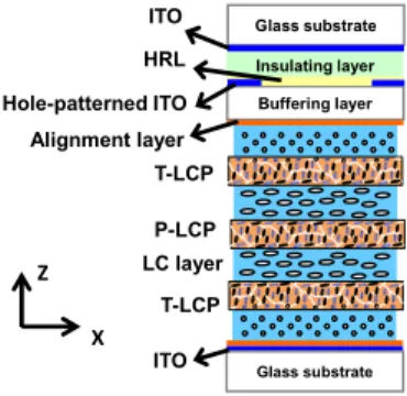
The structure of the multilayered LC lens, as depicted in Fig. 1, is composed of two planar layers of indium tin oxide (ITO) as electrodes coated on glass substrates with thickness of 0.4 mm, one hole-patterned ITO layer as another electrode with a diameter of 10 mm, an insulating layer of the polymer (NOA 81, Norland) with thickness of 35 μm, one buffering layer of glass with thickness of 400 μm, a high resistive layer (HRL) with thickness < 100 nm, two alignment layers to align LC molecules, four LC layers, and three LCPCF as separators. The HRL was made up of PEDOT-PSS (Agfa, S300) mixed with polyvinyl (PVA). After we placed the HRL mixture on the substrate with a hole-patterned electrode with a spin speed of 3500 rpm, the coated substrate was then baked at 120oC for 1 hour hard bake. The function of HRL is to assist distributing the electric fields to the entire aperture. The materials of four LC layers were nematic LC mixture of LCM-1790 (LCMatter Corp., LCM-1790, Δn= 0.4172 for λ= 589 nm at 21oC). The thickness of each LC layer was 50 μm. As to the LCPCF or polymeric layers, the LCPCF is classified as T-LCP and P-LCP according to the alignment directions of two surfaces of a film. Where T-LCP has the orthogonal alignment directions and P-LCP has parallel alignment directions.[15] The detail fabrication of LCPCFs are introduced in the next section. The LC lens can be operated as positive or negative lens depending on the electric fields. When the electric field in the central region of the aperture is higher than the rim region of the aperture, the LC lens is operated as a negative lens because the LC molecules in central region are more perpendicular to the glass substrates. On the contrary, the LC lens functions as a positive lens when the electric field in the rim is higher than the center. The reason why the LC layers are orthogonal pairs is because we need the orthogonal pair to remove the polarization dependency and off-axis performance and more pairs of orthogonal layers helps to enlarge the lens power. The detail operating principles and mechanism are introduced mathematically in another published paper of ours. [15, 16] The LC lens with multilayered structure can achieve properties of polarizer-free, large aperture size and large tunable lens power. The aperture size is no longer limited by the power law of the LC lens
ITO Hole-patterned ITO LC layer T-LCP Alignment layer ITO P-LCP HRL X Z Glass substrate Buffering layer Insulating layer Glass substrate T-LCP
3. EXPERIMENT AND RESULTS
Two kinds of cell separators or LCPCF (i.e. T-LCP and P-LCP) are introduced as follows. As depicted in Fig. 1, P-LCP is referred to the LCPCF on which both surfaces provide capability of anti-parallel alignments to LC molecules, whereas T-LCP is referred to the LCPCF on which both surfaces provide capability of orthogonal alignments. Moreover, P-LCP and T-LCP are optically isotropic because the optical axes in the bulk regions of the films are parallel to z-direction. The detailed fabrication process of P-LCP and T-LCP is described as follows. We filled nematic LC (Merck, MLC2144, Δn=0.2493 for λ= 589.3 nm at 20oC), reactive mesogen (Merck, RM257), and photoinitiator (Merck, IRG-184) at 20:79:1 wt. % ratios into the gap between two ITO glass substrates. A pair of ITO glass substrates was coated with mechanically buffered polyimide (PI) whose buffering (or rubbing) directions were either orthogonal for T-LCP or anti-parallel for P-LCP. Thereafter, the pair of ITO substrates filled with the mixture was applied with a voltage of 250 Vrms at a frequency (f) of 1 kHz and then the samples were exposed to UV light ~3 mW/cm2 for 1 hour for photo-polymerization. After photo-polymerization, we peeled off the glass substrates by a thermal releasing process and obtained T-LCP and P-LCP with thickness of 35 μm.
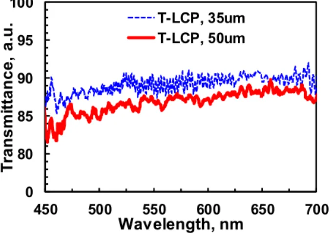
To measure the transmittance of the LCPCFs, a spectrometer (USB2000, Ocean Optics) was used to measure the transmission spectrum of the light after light passed through the LCPCFs. A collimated white light (LSH-150F, Taiwan Fiber Optics) was used as the light source. The transmission spectrums of T-LCP with thickness of 35 μm and T-LCP with thickness of 50 μm were measured. The experimental results are shown in Fig. 2. In Fig. 2, the transmission spectrum shows small dispersion in visible region. The transmittance of the T-LCP at λ=550 nm are 89.0 % for the sample thickness of 35 μm and 86.9 % for sample thickness of 50 μm, respectively. The loss of transmittances is mainly due to Fresnel reflections, scattering and absorption of the T-LCP. After removing the Fresnel reflections, the transmittances of the T-LCP (35 μm) and T-LCP (50 μm) are 96.8 % and 94.5 %, respectively. We also measured the thickness variations of the LCPCFs, where it shows about 4.2% in variation from designed thickness of 50 μm and around non-uniformity of 3.37 μm in testing areas of 900 mm2. From the experimental results, LCPCFs are highly transparent in visible region.
0 80 85 90 95 100 450 500 550 600 650 700 T ran s m it ta n c e, a. u . Wavelength, nm T-LCP, 35um T-LCP, 50um
Both of T-LCP and P-LCP can align LC molecules. The anchoring energy of the LCPCFs indicating the alignment capability is measured. To estimate the anchoring energy of the LCPCF, we adopted the response time model to analyze the LC materials under different anchoring conditions. The relations between anchoring energy (W) and the fall time (τ) of LC response can be written as: d d K
W γ τ π ⋅ ⋅ ≈ 1 ⋅ 2+ 11 2 4
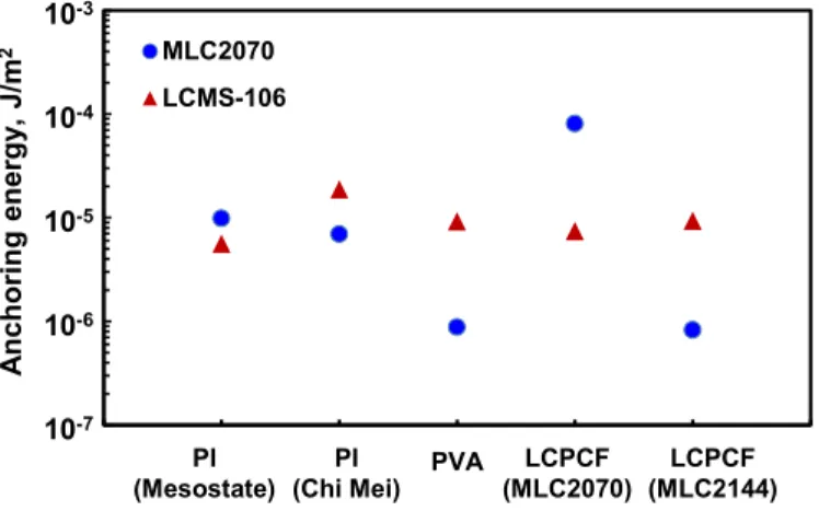
( ) , where γ1 is the rotational viscosity, d is the cell gap of the test cell, and K11 is the splay elastic constant.[17] We prepared LC cells consisting of two ITO glass substrates coated with different materials of alignment layers, such as polyimide from Mesostate International Co., Ltd, polyimide from Chi Mei Corporation, PVA (polyvinyl), LCPCFs whose one of ingredient is MLC2144(Merck), and LCPCFs whose one of ingredient is MLC2070(Merck). The LC between glass substrates coated with ITO and alignment layers is MLC2070 (from Merck) or LCMS-106 (from Liquid Crystals Materials Supplies Ltd. Co.). The rubbing directions of the LC cells with thicknesses of ~55 μm using polyimide and PVA are anti-parallel. The measured anchoring energy are shown in Fig. 3. According to Fig. 3, the anchoring energy for MLC2070 is 9.9 10× −6J/m2, 6.9 10× −6 J/m2, 8.8 10× −7 J/m2,
5
8.1 10× − J/m2, and 8.3 10× −7 J/m2 for PI (Mesostate), PI (Chi Mei), PVA, and LCPCF (MLC2070), and LCPCF (MLC2144), respectively. Meanwhile, the anchoring energy for LCMS-106 is 5.6 10× −6 J/m2, 1.9 10× −5 J/m2,
6
9.2 10× − J/m2, 7.4 10× −6J/m2, and 9.3 10× −6J/m2 for the above alignment layers in order, respectively. The measured results indicate that the anchoring energy of LCPCF is comparable to the commercial materials of the alignment layers. In addition, we also observed the anchoring energy of LCPCF varies for different kinds of nematic LC of LCPCFs. From Fig. 3, the anchoring energy of LCPCFs is larger when the ingredient composite of LC materials of the LCPCFs and LC host we would like to align are identical.
1.0E-07 1.0E-06 1.0E-05 1.0E-04 1.0E-03 0 1 2 3 4 5 6 MLC2070 LCMS-106 LCPCF (MLC2070) PI (Mesostate) PVA PI (Chi Mei) LCPCF (MLC2144) A n cho rin g en ergy , J/ m 2 10-3 10-4 10-5 10-6 10-7
Fig. 3 The measured anchoring energy of different alignment layers.
To further test the surface properties of the LCPCFs, the AFM images using Atomic Force Microscopy (AFM, high vacuum scanning probe microscope (SEIKO SPA-300HV)) and SEM (JEOL JSM-6390LV) are show in Figs. 4(a) and 4(b). As shown in Fig. 4(a) and 4(b), the surfaces of the T-LCP and P-LCP are quite smooth. The measured Root Mean Squared (or RMS) roughness of T-LCP and P-LCP is 0.99 nm and 1.77 nm, respectively. Both the surfaces of Figs. 4(a)
and 4(b) show horizontal lines parallel to the rubbing directions of the substrates before peeling process. The small roughness indicates small scattering and good optical qualities of the films. We also measured the SEM morphologies of the LCPCF, as shown in Fig. 5(a) and 5(b). The LCPCF with P-LCP configuration of 35 μm thicknesses was probed. In Fig. 5(a), the top view of the SEM shows smooth surface which is in accordance with AFM images. In Fig. 5(b), the side view of the LCPCF shows good uniformity with thickness of 30.62 μm. The surface of the LCPCF (i.e. T-LCP or P-LCP) is smooth with good uniformity and indeed a good candidate as the cell separator of LC lenses or optical devices.
Rubbing 1 2 3 4 0 5 12 3 4 05 [nm ] [μ m] [μm] 0.00 6.88 (a) Rubbing 1 2 3 4 0 5 12 3 4 05 [nm ] [μ m] [μm] 0.00 13.60 (b)
Fig. 4 AFM images of (a) T-LCP and (b) P-LCP.
30.62 μm
30.62 μm
Top view 100 nm Side view
(a) (b)
Fig. 5 SEM images of P-LCP at (a) the top view and (b) side view.
To measure the mechanical properties of the LCPCF, we adopt two methods: one is the Tensile test, and the other one is the Bending test. Tensile test is a fundamental test of a material and the testing sample is subject to a controlled tension until the testing sample is failed. The measurement setup (FastTrack 8800 Servohydraulic Test Systems) is shown in Fig. 6(a) and the films are placed between the two loads. During testing process, the elongation of the LCPCF is recorded when the external force is applied, as shown in the Load-Elongation Diagram in Fig. 6(b). The critical point shows the maximum load when the LCPCF experiences permanent deformation. We can also calculate the strain (ε) and stress (σ) by using equation
L
L
ε
=
Δ
and equation FA
σ = , where L is the initial gauge length of the LCPCF, ΔL is the change in gauge length, F is the applied force, and A is the area of LCPCF.[18] The calculated strain and stress are 0.04164 and 15.47 N/mm2, respectively. The results indicate that the modulus of elasticity (stress over strain) is ~0.372 N/mm2 for LCPCF. Comparing to rubber (0.01-1 N/mm2) and nylon (2-4 N/mm2), LCPCF could be a potential substrate
for flexible lenses and displays. The second test is the Bending test which we adopted the three-points bending test model, as shown in Fig. 6(c). The deflection of the LCPCF represents the deformation length when the LCPCF is applied with forces. The experimental result is shown in Fig. 6(d). The critical point for the LCPCF is 1.62 mm under an applied force of 0.59 N. From the experiment we can see that the LCPCF can sustain the weight of the LC layers and is a good candidate as a cell separator.
0 Elongation, mm Critical point Fixture LCP (a ) (c) 1.8 1.5 1.0 0.5 Breaking point LCP Fixture Force 0 1 2 3 4 5 Loa d , N 0 4 12 14 (b ) 8 0 1 2 3 4 Force , N Breaking point Deflection, mm Critical point Load (d )
Fig. 6 The experimental setups for (a) the Tensile test and (c) the Bending test, and the corresponding results are shown in (b) and (d).
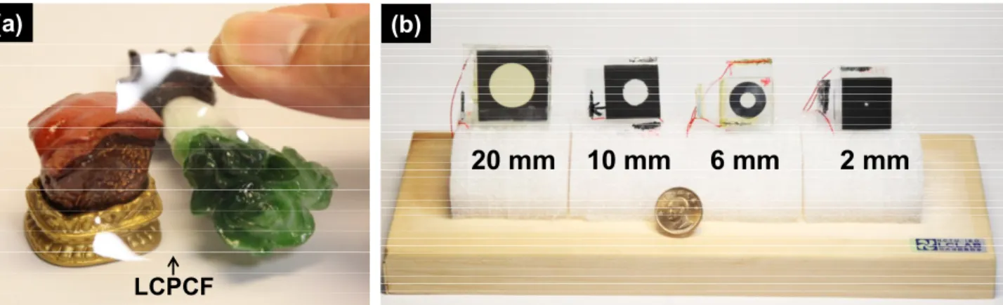
By adopting the LCPCF into our multilayered LC lens ( sample structure depicted in Fig. 1), we have developed multilayered LC lens with different aperture sizes, as shown in Fig. 7. The aperture size ranges from 2 mm to 20 mm. The tunable lens power depends on the aperture size. Now, the maximum tunable lens power we can achieve around 40 Diopter (D or 1/m) for the aperture size of 2 mm, ~ 10 D for the aperture size of 6 mm, ~ 6 D for the aperture size of 10 mm, and ~ 1.5 D for the aperture size of 20 mm.
20 mm
10 mm
6 mm
2 mm
LCPCF
(a)
(b)
4. CONCLUSION
We investigate the physical properties of the LCPCF, such as the transmission spectrum, anchoring energy, thickness variation, and surface roughness of the LCPCF. The transmittance of the LCPCF is over 95% and it shows comparable anchoring energies with other standard alignment technology. The surface roughness of the LCPCF is less than 2nm, which also indicates good optical quality with less scattering. The mechanical properties such as tensile strength and bending strength were also studied, where the LCPCF shows potential as promise candidate for future applications onLC lens, flexible displays and wearable devices. We believe LCPCF can have more photonic devices or biosensing applications.
ACKNOWLEDGMENT
This research was supported partially by Department of Natural Sciences and Sustainable Development in Ministry of Science and Technology (MOST) in Taiwan under the contract no. NSC 101-2112-M-009 -011 -MY3 and partially by Liqxtal Technology Inc.
REFERENCE
[1] M. Ye, M. Noguchi, B. Wang, and S. Sato, “Zoom lens system without moving elements realized using liquid crystal lenses,” Electron. Lett. 45, 646 (2009).
[2] Y. H. Lin, M. S. Chen, and C. H. Lin, “An electrically tunable optical zoom system using two composite liquid crystal lenses with a large zoom ratio,” Opt. Express 19, 4717-4721 (2011).
[3] M. Kawamura, M. Ye, and S. Sato, “Optical Trapping and Manipulation System Using Liquid-Crystal Lens with Focusing and Deflection Properties,” Jpn. J. Appl. Phys. 44, 6098 (2005).
[4] H. C. Lin, N. Collings, M. S. Chen, and Y. H. Lin, “A holographic projection system with an electrically tuning and continuously adjustable optical zoom,” Opt. Express 20, 27222-27229 (2013).
[5] H. C. Lin and Y. H. Lin, “An electrically tunable focusing pico-projector adopting a liquid crystal lens,” Jpn. J. Appl. Phys. 49, 102502 (2010).
[6] Y. S. Tsou, Y. H. Lin, and A. C. Wei, “Concentrating Photovoltaic System Using a Liquid Crystal Lens,” IEEE Photonics Technol. Lett. 24, 2239-2242 (2012).
[7] H. C. Lin, and Y. H. Lin, “A fast response and large electrically tunable-focusing imaging system based on switching of two modes of a liquid crystal lens,” Appl. Phys. Lett. 97, 063505 (2010).
[8] H. S. Chen, Y. J. Wang, C. M. Chang, Y. H. Lin, “A polarizer-free liquid crystal lens exploiting an embedded-multilayered structure,” Photonics Technol. Lett. (2015, in press).
[9] H. S. Chen, and Y. H. Lin, “An endoscopic system adopting a liquid crystal lens with an electrically tunable depth-of-field,” Opt. Express 21, 18079 (2013)
[10] B. Wang, M. Ye, and S. Sato, “Liquid crystal lens with focal length variable from negative to positive values,” IEEE Photonics Technol. Lett. 18, 79-81 (2006).
[11] X. Shen, Y. J. Wang, H. S. Chen, X. Xiao, Y. H. Lin, B. Javidi, “Extended depth-of-focus 3D micro integral imaging display using a bifocal liquid crystal lens,” Opt. Lett. 40, (2015, in press)
[12] H. S. Chen, Y. H. Lin, C. M. Chang, Y. J. Wang, A. K. Srivastava, J. T. Sun, and V. G. Chigrinov, “A polarized bifocal switch based on liquid crystals operated electrically and optically,” J. Appl. Phys. 117, 044502 (2015). [13] S. Sato, “Applications of liquid crystals to variable-focusing lenses,” Optical Review 6, 471-485 (1999).
[14] H. C. Lin, M. S. Chen, and Y. H. Lin, “A review of electrically tunable focusing liquid crystal lenses,” Trans. Electr. Electron Mater. 12, 234-240 (2011).
[15] Y. H. Lin, H. S. Chen, H. C. Lin, Y. S. Tsou, H. K. Hsu, and W. Y. Li, “ Polarizer-free and fast response microlens arrays using polymer-stabilized blue phase liquid crystals,” Appl. Phys. Lett. 96, 113505 (2010).
[16] Y. H. Lin, and H. S. Chen, “Electrically tunable-focusing and polarizer-free liquid crystal lenses for ophthalmic applications,” Opt. Express 21, 9428-9436 (2013).
[17] X. Nie, R. Lu, H. Xianyu, T. X. Wu, and S. T. Wu, “Anchoring energy and cell gap effects on liquid crystal response time,” J. Appl. Phys. 101, 103110 (2007).
[18] D. R. Askeland, P. P. Fulay, and W. J. Wright, The Science and Engineering of Materials, 6th Ed., Cengage Learning. Inc., America (2012).