Bidirectional colorless wired and wireless WDM-PON with improved dispersion
tolerance for radio over
fiber
L. Xu
a,⁎
, C.W. Chow
b, H.K. Tsang
a aDepartment of Electronic Engineering, The Chinese University of Hong Kong, Shatin, Hong Kong, PR China
bDepartment of Photonics and Institute of Electro-Optical Engineering, National Chiao Tung University, Hsinchu 30010, Taiwan
a b s t r a c t
a r t i c l e i n f o
Article history: Received 11 May 2010
Received in revised form 4 January 2011 Accepted 31 March 2011
Available online 24 April 2011 Keywords:
Passive optical network Signal remodulation Optical carrier suppress Subcarrier modulation
Wired and wireless access network
We propose and demonstrate a bidirectional transmission, hybrid wired and wireless access network based on subcarrier modulation (SCM) techniques. The scheme simultaneously enables the dispersion-tolerant transmission of millimeter (mm)-wave signals for use in wireless access networks, downstream baseband signals for optical wired access networks, and optical continuous-wave (CW) carriers for use in upstream data remodulations. Error-free transmissions through a 25-km length of single modefiber (SMF) for both the downstream baseband and the remodulated upstream signals are confirmed by bit-error-rate (BER) measurements. The dispersion tolerance of the radio-over-fiber (RoF) signal is assessed using numerical simulations.
© 2011 Elsevier B.V. All rights reserved.
1. Introduction
Passive optical networks (PONs) for the distribution of both high-speed wired and wireless networks may help to reduce cost for future deployment of broadband networks[1]. It is possible to consolidate the carrier frequency generation and data modulation at the head-end station of a radio-over-fiber (RoF) system. In this system, the downstream signal is distributed by conventional opticalfiber to the remote antenna units (RAUs), thus reducing the cost and complexity of the antenna sites. As a result, RoF technology is considered as one of the most promising solutions for millimeter (mm)-wave wireless signal distribution[2].
The generation and transmission of mm-wave signals are crucial in RoF systems. However chromatic dispersion can cause signal distortions if the mm-wave signal is directly modulated on the optical carrier. The double-sideband (DSB) optical mm-wave signal suffers from both fading effects (fading leads to cosine-like signal power fluctuation along the fiber) and the time-shifting of data codes[3,4]. The fading profile along a length of dispersive fiber has already been described[5–8]. And the effects of the dispersion-induced RF power fading have also been discussed [5–8]. Optical carrier suppressed (OCS) optical mm-wave signals have been proposed[3,4]to mitigate the aforementioned fading effects. However, code time shifting is severe, and distorts the signal, causing eye closure after transmission. Optical single-sideband (SSB) mm-wave signals can reduce the code
time-shifting; however the immunity depends on the generation methods[4]. Besides, wavelength-division-multiplexed (WDM) PON is a promising approach for optical wired communications in future broadband access networks. As a result, the integration of optical wired and wireless access networks into the same system is desirable. Different schemes of optical wired/wireless access networks have been demonstrated [9–12]. For example, polarization-multiplexed (PolMUX) scheme was proposed to simultaneously provide broad-band wireless and wired services [9], but the mm-wave signal suffered fromfiber dispersion seriously. Hybrid subcarrier modulation (SCM) scheme was used for wired and wireless transmission[10]. In [11], the DSB modulation scheme only allowed a low data rate because of dispersion. In[12], a remote all-optical upconversion was proposed with a local exchange unit. Recently, a RoF system supporting 2.5-Gb/s data rate on a 40-GHz mm-wave carrier has been reported[13], however, the upstream path of the system and dispersion tolerance of the mm-wave signal as well as the phase distortion due to the different path are yet to be studied.
In this paper, we propose and experimentally demonstrate a scheme for hybrid wired and wireless access networks based on SCM techniques. We generate two sidebands by OCS and modulate only one subcarrier at the head-end station. By beating the two coherent sidebands at a photodetector in the RAU, a 40-GHz mm-wave signal that carries a 10-Gb/s data is generated for broadband wireless transmission. For the wired connections in PON, the downstream baseband data can be obtained by opticalfiltering to extract the data from the downstream signal. The unmodulated optical CW-like sideband can be used for upstream remodulation. The proposed scheme therefore supports a colorless optical network unit (ONU) for
Optics Communications 284 (2011) 3518–3521
⁎ Corresponding author. Tel.: +852 26098252; fax:+852 26035558. E-mail address:[email protected](L. Xu).
0030-4018/$– see front matter © 2011 Elsevier B.V. All rights reserved. doi:10.1016/j.optcom.2011.03.085
Contents lists available atScienceDirect
Optics Communications
PON as well as RAU for ROF. Analysis using VPI TransmissionMa-kerV7.1 is also performed and compared with the experimental results.
2. Experiment and simulation
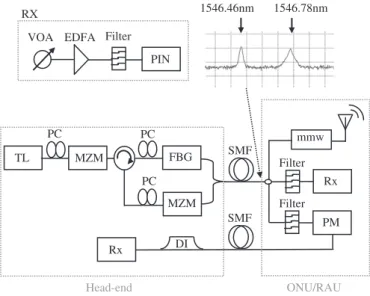
Fig.1shows the experimental setup of the proposed hybrid optical wired and wireless network. A CW signal at the wavelength of 1546.6 nm generated by a tuneable laser (HP 8168F) was launched into thefirst Mach–Zehnder modulator (MZM) to generate OCS signal. The MZM was electrically driven with a 20-GHz RF tone. By setting the DC bias to the transmission minimum of the MZM, the optical carrier was suppressed and twofirst order sidebands were generated. The frequency separation between the two sidebands was twice the modulation frequency. Hence this produced a 40-GHz optical carrier. A fiber Bragg grating (FBG) with 3-dB bandwidth of 0.1 nm transmitted one sideband at 1546.46 and reflected the other sideband at 1546.78 nm as shown inFig. 1inset, which was then obtained at the output port of the optical circulator. The reflected sideband was then modulated with 10-Gb/s (231-1 PRBS) non-return-to-zero (NRZ) data via the second MZM, which was biased at the linear transmission region. After that, the two sidebands were combined by a 3-dB coupler and launched into a 25-km single modefiber (SMF) without any dispersion compensation. Due to the optical path length difference, the phase of the two sidebands may be distorted. We measured the phase noise for the case of 5-m path length difference and compared it with the case of none path length difference as shown inFig. 2. There was a 1.2-dB variation observed. The average optical power launched into thefiber was about 0 dBm in order to avoid nonlinear effects in the opticalfiber.
At the ONU/RAU, 10% signal power was tapped out for wireless transmission. The two sidebands beat at the 40-GHz photodetector and generated a 40-GHz mm-wave signal. Numerical analysis using VPI was also performed.Fig. 3(a) shows the simulated RF spectrum when the NRZ data at the head-end station was turned OFF. Only a 40-GHz tone (generated by the coherent beating of the DSB-OCS) was observed inFig. 3(a). When the NRZ data was turned ON, other RF components around the 40-GHz tone and the 10-GHz, 20-GHz and 30-GHz tones also appeared as shown inFig. 3(b). The experimental RF spectrum when the NRZ data was ON is shown inFig. 3(c). We can see that there is a good match between the simulation and the experimental result.
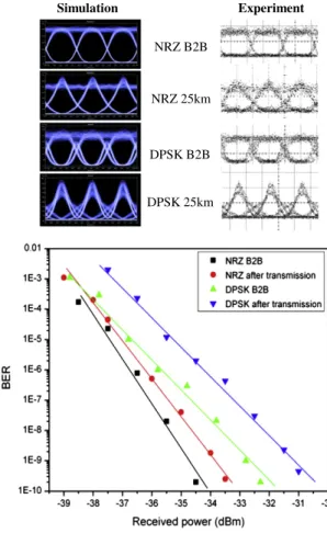
As we did not have a 40-GHz RF mixer for the wireless signal down-conversion, we measured the self-beating 10-Gb/s NRZ signal carried in the RoF signal. An electrical low pass filter with 3-dB bandwidth of 7.5 GHz was connected after the PD to obtain the 10-Gb/ s NRZ signal. Here, we also compared the dispersion tolerance (transmission in 25-km SMF without dispersion compensation) of our scheme with the conventional mm-wave signal carried by the DSB carrier in which both of the sidebands carried a 10-Gb/s signal while there was a 40-GHz separation between the two sidebands. The eye-diagrams (measured after a low-passfilter) of the conventional DSB optical mm-wave signal and the proposed SCM optical mm-wave signal are shown inFig. 4. It can be found that the SCM scheme has a higher dispersion tolerance than the conventional DSB optical mm-wave signal due to the reduction of both the fading effects and the time-shifting of data code.
For the upstream transmission, the opticalfiltered CW sideband was modulated by a phase modulator (PM) at the ONU/RAU to produce the 10-Gb/s, (231-1 PRBS) differential-phase-shift-keyed (DPSK) upstream signal. It was then launched towards the head-end receiver. Bit-error-rate (BER) and the corresponding eye-dia-grams for both downstream NRZ (square- and round-shape) and upstream DPSK (up- and down-triangle shape) were measured as shown inFig. 5 bottom. Power penalties of the downstream NRZ signal and upstream DPSK signal after 25-km SMF were 1 and 1.5 dB respectively. The corresponding simulated and experimental eye-diagrams are shown inFig. 5top. The unequal noise level in the eye-diagram comes from the amplified spontaneous emission (ASE) noise of the erbium-doped fiber amplifier (EDFA), the fiber chromatic dispersion and the unequal scale of digital communications analyzer. For the DPSK eye-diagrams, it may also come from different ports of the delay-interferometer (DI) used. We used NRZ pattern for the downstream in order to keep the receiver at ONU site simple. Although the NRZ pattern may also be used for the upstream transmission, DPSK was used for the upstream because of its potential improved receiver (Rx) sensitivity. The DI used for the upstream DPSK demodulation was located at the head-end station. An arrayed waveguide grating (AWG) can be used between the DI and the Rx, and assuming that the transmitted wavelengths at the head end are tuned to give the required phase shift in the DI, only a single DI can be used to demodulate all the upstream DPSK channels. The 40-GHz optical bandwidth is required for carrying the 40-GHz RoF signal, together with the 10-Gb/s downstream NRZ channel. Since the upstream signal is generated by modulating one of the two sidebands coming from the downstream RoF signal, no extra wavelength channel is required.
Simulation using VPI was performed to evaluate the mm-wave signal. In the simulation, a high speed photodiode followed by an
TL MZM FBG MZM SMF Rx Head-end Filter PC mmw Filter PM DI SMF Rx ONU/RAU VOA EDFA PIN RX 1546.46nm 1546.78nm PC PC Filter
Fig. 1. Experimental setup: TL = tunable laser; MZM = Mach Zehnder Modulator; FBG = Fiber Bragg Gratingfilter; SMF = single mode fiber; MMW = millimeter wave; PM = optical phase modulator; DI = Optical Delay Interferometer; and PC=polarization controller.
0 1 2 3 4 5 -87.8 -87.6 -87.4 -87.2 -87.0 -86.8 -86.6 dBc/Hz
Path length difference (m)
Fig. 2. Measured phase noise against path length difference.
3519 L. Xu et al. / Optics Communications 284 (2011) 3518–3521
electrical Bessel bandpassfilter (passband at 40 GHz, 3-dB bandwidth of 18 GHz) was used to detect the mm-wave signal (10-Gb/s data on the 40-GHz mm-wave signal). The time trace of the mm-wave signal is shown in the inset (a) ofFig. 6. In order to evaluate the mm-wave signal, BER measurements using the built-in modules of VPI were performed. The mm-wave signals were down-converted by using a RF mixer to baseband signal for back-to-back (B2B) and after the transmission of 25-km SMF without dispersion compensation.Fig. 6shows that the power penalty of the down-converted mm-wave signal was about 1 dB after the 25-km SMF transmission, showing that the proposed scheme has a
Fig. 3. RF spectrum after 25-km transmission. (a) Simulated RF spectrum when the NRZ data at the head-end station was turned OFF. (b) Simulated RF spectrum when the NRZ data is turned ON. (c) Experimental RF spectrum when the NRZ data is ON.
DSB
Proposed
Fig. 4. Eye-diagrams of the baseband signal on 40-GHz mm-wave carrier after transmission of 25-km SMF transmission using conversional DSB modulation and the proposed SCM modulation. NRZ B2B NRZ 25km DPSK B2B DPSK 25km Simulation Experiment
Fig. 5. Top: simulated and experimental eye-diagrams; Bottom: BER performance for downstream and upstream services versus received optical power; B2B: back-to-back.
-12 -11 -10 -9 -8 -7 -6 -5 -4 -3 -2 -36 -34 -32 -30 -28 -26
Received optical power (dBm)
Log (BER) B2B 25km SMF (a) (b) (c)
Fig. 6. BER of the down-converted mm-wave signals at B2B and after 25-km of SMF transmission. Inset (a) time trace of the mm-wave signal; down converted mm-wave signal eye-diagrams of (b) back to back and (c) after 25-km SMF transmission.
high chromatic dispersion tolerance for the RoF signal. The eye-diagrams of the corresponding down-converted signals were included in insets ofFig. 6.
3. Conclusion
We have demonstrated the simultaneous generation and trans-mission of the 10-Gb/s signal carried by a 40-GHz mm-wave carrier using the SCM for hybrid wired and wireless access networks with colorless ONUs. The SCM scheme has been confirmed with an improved chromatic dispersion tolerance. Upstream 10-Gb/s DPSK remodulation on the optical CW-like sideband filtered from the downstream signal has also been studied. Simulations have been performed; showcasing the proposed scheme has improved chro-matic dispersion tolerance for the RoF signal. The experiment results of both the downstream NRZ signal and upstream DPSK signal agree well with the simulations.
Acknowledgments
This work was supported in full by CUHK group research project 3110049. C. W. Chow would like to acknowledge NSC— 98-2221-E-009-017-MY3 and 99-2622-E-009-013-CC2.
References
[1] Z.S. Jia, J.J. Yu, G. Ellinas, G.K. Chang, J. Lightw. Technol. 25 (2007) 3452. [2] M. Weiß, M. Huchard, A. Stöhr, B. Charbonnier, S. Fedderwitz, D.S. Jäger, J. Lightw.
Technol. 26 (2008) 2424.
[3] J. Yu, M.F. Huang, Z. Jia, T. Wang, G.K. Chang, IEEE Photon. Technol. Lett. 20 (2008) 478.
[4] J. Ma, J. Yu, C. Yu, X. Xin, J. Zeng, L. Chen, J. Lightw. Technol. 25 (2007) 3244. [5] E. Vourc'h, B. Della, D. Le Berre, D. Herve, IEEE Trans. Microw. Theory Tech. 50
(2002) 3009.
[6] R. Hofstetter, H. Schmuck, R. Heidemann, IEEE Trans Microw. Theory Tech 43 (1995) 2263.
[7] U. Gliese, S. Norskov, T.N. Nielsen, IEEE Trans. Microw. Theory. Tech. 44 (1996) 1716.
[8] G.H. Smith, D. Novak, Z. Ahmed, IEEE Trans. Microw. Theory Tech. 45 (1997) 1410. [9] J.Q. Li, K. Xu, Y.J. Wen, S.N. Fu, M. Tang, P. Shum, J. Wu, J.T. Lin, Optics Comm. 281
(2008) 2806.
[10] S.H. Fan, H.C. Chien, Y.T. Hsueh, A. Chowdhury, J.J. Yu, G.K. Chang, IEEE Photon. Technol. Lett. 21 (2009) 1127.
[11] J.J. Yu, Z.S. Jia, T. Wang, G.K. Chang, IEEE Photon. Technol. Lett. 19 (2007) 140. [12] L. Xu, C.W. Chow, H.K. Tsang, IEEE Trans. Microw. Theory Tech. 58 (2010) 3136. [13] A. Wiberg, P. Perez-Millan, M.V. Andres, P.A. Andrekson, P.O. Hedekvist, IEEE
Photon. Technol. Lett. 17 (2005) 1938.
3521 L. Xu et al. / Optics Communications 284 (2011) 3518–3521