In conclusion, an integrated tapped delay line structure consisting of a coplanar waveguide transmission line with Schottky diode peak detector taps has been fabricated. The structure was driven with two pulse compressor circuits producing two 20pS pulse trains. The relative phases of the two inputs were determined from the position along the struc- ture of the collision event as captured by the hold capacitors. Shifts of 1 pS in the trigger input signal were easily detectable during steady state testing of the structure. Improvements in the current resolution should be possible with better pulse compression circuits yielding greater slew rates for input pulses and reduced dispersion due to tap discontinuities by further distribution of the taps along the line. Finally, when coupled with external processing circuitry the C P P D should be capable of picosecond resolution detection of trigger events in one-shot or in steady state.
A c k n o w l e d g m e n t : This work has been supported by DARPA under contract # “14-87-C-0363.
A. BLACK E. OZBAY B. A. AULD D. M. BLOOM
Edward L. Ginrton Laboratory Stanford University Stanford, C A 94305-4085, U S A References
21s June 1991
STEPHENSON, P. s.: ‘Frequency and time interval analyzer measure- ment hardware’, Hewlett-Packard J., 1989,40, (I), pp. 3 5 4 1 CHU, U. e., ALLEN, M. s., and FOSTER, A. s.. ‘Universal counter resolves picoseconds in time interval measurements’, Hewlett- Packard J . , 1979,29, (12), pp. 2-11
SKOLNICK, M. I.: ‘Receivers, displays, and duplexers’, in ‘Intro- duction to radar systems’ (McGraw-Hill Book Company, New York, 1980). Chap. 9
RODWELL, M. I., BLOOM, D. M., and AULD, B. A . : ‘Nonlinear transmis- sion line for picosecond pulse compression and broadband phase modulation’, Electron. Lett., 1987, 23, (3). pp. 109-1 10
MADDEN, e. J., MARSLAND, R. A., RODWELL, M. J , and BLOOM, U. M . : ’Hyperabrupt-doped GaAs nonlinear transmission line for picose- cond shock-wave generation’, Appl. Phys. Lett., 1989, 54, ( I I ) , pp. 101 9-1021
ELECTRO-OPTIC SAMPLING
OF
OPTOELECTRONICALLY PHASE- LOCK ED 10.OGHz MICROWAVE SIGNALS USING S E M I C 0 N D U C T 0 R LASER DIODES
Indexing t e r m Optical measurement, Lasers and laser appli- cations, Photoconducting devices. Phase-locked loops. Electro- optics. Semiconductor lasers
I0.0GHz microwave signals optoelectronically phase locked by a laser-diode-based GaAs : Cr photoconductive harmonic mixer (A = 0.81 pm) have been measured noninvasively using the electro-optic sampling technique with a gain-switched InGaAsP laser diode (1 = 1.3pm).
The electro-optic sampling (EOS) technique’.’ has been shown to be a very powerful tool for measurement of electrical waveforms noninvasively at internal nodes of discrete elec- tronic devices and integrated circuits. Compact laser-diode- based EOS systems have also been demonstrated by several groups r e ~ e n t l y . ~ In these systems, i t is essential that phase coherence or time synchronisation is maintained between the optical probe pulses and the continuous wave (CW) micro- wave waveform to be measured. Recently, Li e t al.6 demon-
strated optical phase locking of microwave signals up to 1.3 G H z by intermixing microwave signals with the harmonics of the optical probe pulse using the electro-optic effect in
GaAs microstrip circuits. The signals were then displayed using the photoconductive sampling technique.’,” This novel technique is potentially useful for diagnostics of millimetre wave integrated circuits (MMICs) up t o l 0 0 G H z at the wafer level. In a previous Letter,’ we demonstrated optoelectronic phase locking of microwave signals up to 12.01 GHz using a laser-diode-based GaAs : Cr photoconductive harmonic mixer. In this Letter, we report for the first time electro-optic sampling of 10.0 GHz optoelectronically phase-locked micro- wave signals using semiconductor laser diodes.
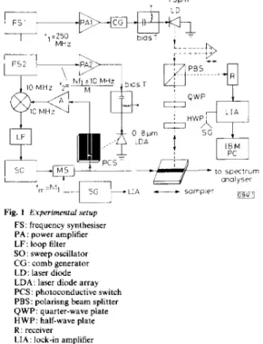
Our experimental apparatus is shown in Fig. 1. It consists of an optoelectronic phase-locked loop (OEPLL) and an
Fig. 1 Experimental setup FS: frequency synthesiser PA: power amplifier LF: loop filter SO: sweep oscillator C G : comb generator LD: laser diode LDA: laser diode array PCS: photoconductive switch PBS: polarisng beam splitter QWP: quarter-wave plate HWP: half-wave plate R: receiver LIA: lock-in amplifier
electro-optic sampling system. Two electronically phase- locked synthesisers were used t o gain switch a laser diode array (LDA, Spectra Diode Laboratories, model SLD-2410, I. = 0.81 pm) at f 2 and a n InGaAsP laser diode (LD, Toshiba,
model TOLD-300, I = 1.3pm) at fi, respectively. In the OEPLL, a free running signal at
f,
from a microwave sweep oscillator (HP8620C), simulating the monolithic device, was used to bias a GaAs : Cr switch with 10pm gap and inter- mixed with the appropriate harmonic component of the elec- trical pulses generated by l00ps optical pulses from the LDA illuminating the switch. The signal at the output port of the switch was amplified by a low-noise 26dB-gain amplifier and mixed with the 10 MHz reference signal of the frequency syn- thesiser (HP8657A) at f z . The detected error signal was used to phase lock the sweep oscillator which operates as a voltage- controlled oscillator (VCO) via a loop filter. In the present experiment, f i = 250 MHz,f,
= Nfl, and f z = (Nfl f IOMHz)/M, where M , N are integers. Fig. 1 IS the instrument-limited spectrum of the 10.0 G H z optoelectroni- cally phase-locked signal, exhibiting minimal sidebands.This signal was either amplitude modulated or chopped with a microwave switch at 1.OkHz and sent to the EOS also shown in Fig. 2. We used the standard reflection-mode probing geometry. A train of 30ps optical pulses from the gain-switched and phase-locked 1.3pm L D was sent through a polarising beam splitter (PBS), a quarter-wave plate (QWP)
* wu, H.-H., CHANG, c.-s., and PAN, c.-L.: ’Optical phase-locking of
microwave signals up to 12GHz by laserdiode-based GaAs : Cr
photoconductive harmonic mixer’, submitted to Electron. Lett., 1991
and a half-wave plate (HWP) and focused on the ground plane of a GaAs microstrip transmission line used as the
-20 -3 0 -LO -50 -60 - 70 E m TI IO 00000311 frequency, GUz
Fig. 2 Specrrum oJ 10.0 G H z optoelecrronically phase-locked signal
Resolution BW = l00Hz Frequency span = 500 Hz/division Amplitude scale = lOdB/division
sampler. The microwave signal changes the polarisation of the reflected probe beam which passes back through the lens and the waveplates. The probe pulses were then directed by the beamsplitter to a G e photodiode and processed by a lock-in amplifier. Several cycles of the 10,OGHz signal were observed as the optical probe pulses were scanned across the micro- wave waveform by employing an optical delay line. This is shown in Fig. 3. It is worth noting that the microwave signal
2 WEINGARTEN, K . J., RODWELL, M. J. w., and BLOOM, D. M.: ‘Picose- cond optical sampling of GaAs integrated circuits’, IEEE J . Quanrum Electron., 1988, QE24, pp. 198-220
NEES, J., and MOUROU, G . : ‘Noncontact electro-optic sampling with a GaAs injection laser’, Electron. L e f t . , 1986, 22, pp. 918-919 WIESENFELO, J. M., and JAIN, R. K . : ‘Direct optical probing of inte- grated circuits and high speed devices’, in MARCUS, R. B. (Ed.): ‘Measurements of high speed signals in solid state devices, semi- conductors and semimetals’ (Academic press, 1990), Vol. 28, pp.
221-334 (and references therein)
TAKAHASHI, R., and KAMIYA, T.: ‘Application of a diode laser ampli- fier to an ultrafast desktop electrooptic sampling system’. 1990
Topical Meeting on Optical Amplifiers, Monterey, CA, USA, paper WC4
mixing optical and microwave signals in GaAs microstrip circuits for phase-locking applications’, IEEE Trans., 1990, hflT-38, pp.
I9241 931
Li, M. G., HUANG, s.-L. L., LEE, c. H., and HUNG, H.-L. A . : ‘Display of microwave waveform via a low frequency replica using an optical phase-locking and sampling technique’. 1991, Topical Meeting on Picosecond Electronics and Optoelectronics, Salt Lake City, Utah, USA, paper WB2-1
HUNG, H.-L. A., LI, M. G., HUANG, s.-L. L., and LEE, c.-H.: ‘Character- ization of microwave integrated circuits using an optical phase- locking and sampling system’. 1991 Int. Microwave Symp., Boston, MA, USA
3
4
5
6 LI, M. G., CHAUCHARO, E. A., LEE, C. H., and HUNG, H.-L. A . : ‘hler-
7
8
INEXACT M A T C H ASSOCIATIVE M E M O R Y CELL
Indexinq terms: Memories. Parallel processing
time delay,lO psldlvl51or ‘C9. 3 Fig. 3 10.0 GHz microwaue signal probed by electro-optic sampling
0 experimental data
~ 10.0GHz sinusoid
can be synchronously probed electro-optically by the 1.3pm LD without offset, i.e. ,fm = N f i , in our scheme.
In summary, we have demonstrated electro-optic sampling of I 0 . 0 G H r optoelectronically phase-locked microwave signals using semiconductor laser diodes. One potential appli- cation of this technique is for the characterisation of MMICs at the wafer level.
A c k n o w l e d g m e n t : This work was partially supported by the National Science Council of the Republic of China under grant NSCSO-0417-E-009-05.
H.-H. W U 24rh June 1991
C.-S. CHANG
C.-L. PAN
Inst. of Electro-opt. Eng. and C t r . Jar Telecom. Res National Chiao Tung University
Hsinchu. Taiwan 300, Republic of China References
I VALOMANIS J. A . : ‘Electro-optic measurement techniques for pico- second materials, devices and integrated circuits: in MARCUS, R. B. (Ed.): ‘Measurements of high speed signal in solid state devices, semiconductors and semimetals’ (Academic Press, 19901, Vol. 28.
pp. 136219
A new associative memory cell is described and analysed using SPICEMI. The CMOS cell uses current summation to compute, in parallel, Hamming distances between the search key and each word in the memory. For 32 bit words, SPICE simulations of a 2pm process show a delay of 4ns/bit for Hamming distances less than three.
I n t r o d u c t i o n : The first uses of associative memories were in system architectures to improve the translation table lookup process in the cache memory.’ The improvement is the result of the parallelisation of an exact match of a search key t o all words stored in the translation buffer memory. An exact match, B bits in length, can be expressed as
i = 1
where S , is the value of the ith bit of the search key,