A Novel Fluorene-Triphenylamine Hybrid That is a Highly Efficient
Host Material for Blue-, Green-, and Red-Light-Emitting
Electrophosphorescent Devices**
By Ping-I Shih, Chen-Han Chien, Fang-Iy Wu, and Ching-Fong Shu*
1. Introduction
Organic light-emitting diodes (OLEDs) are being investi-gated widely for their potential applications within full-color flat-panel displays.[1]Among these devices, the use of phospho-rescent emitters has stimulated the development of efficient heavy metal-containing electroluminescent guest systems.[2,3] The ability of these phosphorescent dyes to harvest both singlet and triplet excitons can, theoretically, increase the internal effi-ciency of devices up to 100 %.[4–6] In these phosphorescent OLEDs, the triplet emitters are normally used as emitting guests in a host material to reduce the self-quenching asso-ciated with the relatively long excited state lifetimes of triplet emitters and triplet-triplet annihilation; consequently, the choice of host materials is of vital importance for the prepara-tion of efficient phosphorescent OLEDs. The carbazole-based molecule 4,4′-bis(9-carbazolyl)-2,2′-biphenyl (CBP) [glass tran-sition temperature (Tg) = 62 °C][7]has been used frequently as a
host material in green- and red-emitting phosphorescent de-vices—even though the triplet energy of CBP (2.56 eV) is low-er than that of the genlow-eral blue triplet emittlow-ers (> 2.62 eV), resulting in an inefficient energy transfer from host to guest.[8]
To overcome this obstacle, structurally modified host mole-cules, such as 1,3-bis(9-carbazolyl)benzene (mCP), which has a higher-value ET(2.90 eV), have typically been utilized to
fabri-cate blue-emitting OLEDs; bis[(4′,6′-difluorophenyl)pyridina-to-N,C2′]iridium(III) picolinate (FIrpic; ET= 2.65 eV) is the
most popular choice for the dopant.[8]Although mCP possesses a suitable triplet energy, its relatively low thermal and morpho-logical stability [glass transition temperature (Tg)= 60 °C][7]
may hinder its application as a host material in OLEDs. In at-tempts to overcome these problems and realize efficient blue-emitting devices, several carbazole derivatives have been pre-pared, but their syntheses often suffer from drawbacks such as complicated reaction conditions and moderate to low yields.[9,10]
In this paper, we describe the facile synthesis of a novel fluo-rene/triarylamine hybrid (tris[4-(9-phenylfluoren-9-yl)pheny-l]amine, TFTPA)—through a simple one-step reaction from commercially available starting materials—and its superior characteristics that make it suitable for use as a host material in full-color phosphorescent devices. The design of TFTPA was based on triphenylamine and fluorene both possessing large triplet energy gaps (3.04 and 2.95 eV, respectively).[11,12]
Be-cause the triphenylamine unit is connected to the sp3 -hybrid-ized carbon atom at the C-9 position of the fluorene moiety, which serves as a spacer to block extended p-conjugation,[13] the conjugation length and triplet energy of each individual building block in the resulting composite should remain essen-tially unperturbed. In addition, the 3D cardo structure of sub-stituted fluorene derivative should improve the system’s rigid-ity and hinder any unwanted aromatic p-stacking interactions, resulting in an amorphous material possessing enhanced mor-phological stability. More importantly, we expected that the
–
[*] Prof. C.-F. Shu, P.-I. Shih, C.-H. Chien, Dr. F.-I. Wu
Department of Applied Chemistry, National Chiao Tung University Hsinchu, 300 Taiwan (ROC)
E-mail: [email protected]
[**] We thank the MOE ATU Program and the National Science Council for financial support. Our special thanks go to Professor C.-H. Cheng for his support and cooperation during the preparation and charac-terization of the light-emitting devices.
TFTPA (tris[4-(9-phenylfluoren-9-yl)phenyl]amine), a novel host material that contains a triphenylamine core and three
9-phe-nyl-9-fluorenyl peripheries, was effectively synthesized through a Friedel-Crafts-type substitution reaction. Owing to the presence of its sterically bulky 9-phenyl-9-fluorenyl groups, TFTPA exhibits a high glass transition temperature (186 °C) and is morphologically and electrochemically stable. In addition, as demonstrated from atomic force microscopy measurements, the aggregation of the triplet iridium dopant is significantly diminished in the TFTPA host, resulting in a highly efficient full-color phosphorescence. The performance of TFTPA-based devices is far superior to those of the corresponding mCP- or CBP-based devices, particularly in and red-emitting electrophosphorescent device systems. The efficiency of the FIrpic-based blue-emitting device reached 12 % (26 cd A–1) and 18 lm W–1at a practical brightness of 100 cd m–2; the Ir(piq)2acac-based
red-emit-ting device exhibited an extremely low turn-on voltage (2.6 V) and a threefold enhancement in device efficiency (9.0 lm W–1) relative to those of reference devices based on the CBP host material.
FULL
sterically hindered phenyl-substituted fluorene peripheries of
TFTPA would alleviate the triplet-triplet annihilation and
con-centration quenching arising from strong bimolecular interac-tions of the phosphor at high doping levels,[14,15] leading to
highly efficient phosphorescent devices.
2. Results and Discussion
2.1. SynthesisAs illustrated in Scheme 1, the acid promoted Friedel-Crafts-type substitution reaction of triphenylamine (TPA) with 3 equivalents of 9-phenyl-9-fluorenol in 1,4-dioxane solution in the presence of trifluoromethanesulfonic acid at 80 °C for 3 h
afforded TFTPA as a crude white product. This reaction pro-ceeded smoothly through protonation of 9-phenyl-9-fluorenol, generating a transitory carbocation,[16–18]which in turn
under-went Friedel–Crafts-type electrophilic substitution very effi-ciently and exclusively at the electron-rich para carbon atom(s) of the TPA phenyl groups. After cooling, the precipitate was filtered, washed with acetone, and purified through repeated vacuum sublimation to give pure TFTPA (72 %). It is notewor-thy that this overall yield is much higher than that reported for other effective host materials, and that our present preparation method was performed under mild reaction conditions in the absence of expensive noble-metal catalysts. Moreover, because this protocol does not require chromatographic purification of the product, it seems to be suitable for large-scale production. The product TFTPA was characterized using1H and13C NMR spectroscopy, elemental analysis, and high-resolution mass spectrometry.
2.2. Properties
TFTPA exhibits very high thermal stability;
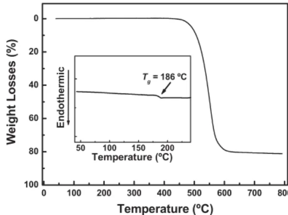
thermogravimet-ric analysis (TGA) performed under a nitrogen atmosphere re-vealed that the onset decomposition temperature was 430 °C, followed by 5 % weight loss at 491 °C. During differential scan-ning calorimetry (DSC) measurements, TFTPA existed in a glassy state after rapid cooling from the melt (at ca. 400 °C) and underwent a glass transition at a relatively high
tempera-ture (Tg= 186 °C). The higher value of Tgfor TFTPA, with
re-spect to those of mCP (Tg= 60 °C) and other carbazole
ana-logues,[7,9,10] is presumably the result of its higher molecular weight and the presence of its rigid fluorene peripheries.[19]
Consequently, TFTPA forms an amorphous glass that is more stable than that of common host materials and, therefore, it is more promising—in terms of its thermal stability—for applica-tion within OLEDs. Figure 1 displays the TGA thermogram and DSC curve of TFTPA. Because of its excellent thermal and morphological stability, we could use vacuum deposition to prepare homogeneous, stable amorphous thin films of TFTPA. Atomic force microscopy (AFM) measurements indicated that
an evaporated film of TFTPA possessed a uniform surface that did not undergo any morphological changes when annealed at 120 °C for 40 h under a nitrogen atmosphere; the root-mean-square surface roughness of this annealed film was very narrow (only 0.32 nm). On the other hand, annealing of a film of mCP, of which the root-mean-square surface roughness was 0.33 nm before annealing, induced the degradation of the surface mor-phology.
We used cyclic voltammetry, with ferrocene as the internal standard, to examine the electrochemical behavior of TFTPA. As indicated in the inset of Figure 2, TFTPA exhibits a revers-ible oxidation process with an oxidation potential (E1/2) of
0.46 V. In contrast, the oxidation process of the pristine TPA is irreversible; this phenomenon can be attributed to the electro-chemical dimerization of TPA through the active para posi-tions.[20]These electrochemical results reveal that the encapsu-lation of TPA with peripheral fluorene moieties at all three of its para-phenyl positions efficiently blocks the electrochemical-ly active sites of TPA and imparts enhanced electrochemical stability.
Figure 2 displays the room-temperature absorption and photoluminescence (PL) spectra of TFTPA recorded from a dilute dichloromethane solution and as a solid film on a quartz substrate. The two strong absorption bands at ca. 267 and
HO
N + N
TFTPA
dioxane CF3SO3H
Scheme 1. Synthesis of TFTPA
0 100 200 300 400 500 600 700 800 100 80 60 40 20 0 50 100 150 200 Temperature (ºC) Endothermic Tg = 186 ºC W e ight L o s s es (% ) Temperature (ºC)
Figure 1. TGA thermogram of TFTPA recorded at a heating rate of
20 °C min–1. Inset: DSC trace of TFTPA recorded at a heating rate of
20 °C min–1.
P
310 nm arose mainly from the absorptions of the fluorene moi-eties and the TPA core, respectively. The TFTPA film exhib-ited PL in the near-UV region with a peak at 377 nm, which was slightly red-shifted (ca. 4 nm) when compared with that obtained from the dichloromethane solution. The small spec-tral shift in the solid state spectra suggests that any intermolec-ular interactions are weak,, i.e., they were restrained effectively by the bulky fluorene peripheries. The fluorescence quantum yield in dilute cyclohexane solution was 0.07 [using 9-phenyl-9H-carbazole (Uf= 0.33) as the reference].[21]Figure 2 also
de-picts the phosphorescence spectra of TFTPA measured from a frozen 2-methyltetrahydrofuran matrix at 77 K. The highest-energy 0–0 phosphorescent emission located at 2.89 eV was used to calculate the triplet energy gap of TFTPA, giving a val-ue higher than that reported for the common triplet blval-ue-emit- blue-emit-ter FIrpic (2.62 eV). Using host mablue-emit-terials that possess high triplet energies is a provision for effective confinement of the triplet excitons on the guest and, consequently, for prevention of back energy transfer between the host and dopant mole-cules.[8,22,23]In this case, the triplet energy of TFTPA is
suffi-ciently high to serve as a decent host for short-wavelength dop-ants, such as FIrpic, and other long-wavelength dopants.
2.3. Electroluminescence Properties of LED Devices
To evaluate the utility of TFTPA as a host material, we fabri-cated blue-, green-, and red-electrophosphorescent device sys-tems using FIrpic, Ir(ppy)3, and Ir(piq)2acac as emitters,
re-spectively, co-evaporated with the host material TFTPA. The typical multilayer architecture consisted of indium tin oxide (ITO)/4,4′-bis[N-(1-naphthyl)-N-phenylamino]biphenyl (NPB) (30 nm)/TFTPA: X (X = 7–21) wt % of dopant (40 nm)/1,3,5-tris(N-phenylbenzimidazol-2-yl)benzene (TPBI) (40 nm)/ Mg:Ag (100 nm)/Ag (100 nm); the fabrication of these EL de-vices—through sequential vapor deposition of the materials onto ITO glass under vacuum (3 × 10⁻⁶Torr)—and their
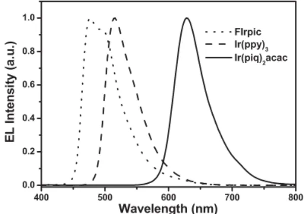
char-acterization were similar to techniques we have reported pre-viously.[24]In these devices, NPB and TPBI were employed as the hole-transporting layer (HTL) and the electron-transport-ing layer (ETL), respectively. For comparison, we also fabri-cated the corresponding blue-emitting control devices using mCP as the host material and FIrpic as the dopant at different doping concentrations (7 and 21 wt %). Figure 3 presents the EL characteristics of the three different color devices (R-G-B); the blue, green, and red emissions originated from the FIrpic, Ir(ppy)3, and Ir(piq)2acac triplet emitters, respectively. The
CIE coordinates of these devices were located at (0.17, 0.37) for the blue-emitting device, (0.26, 0.66) for the green-emitting device, and (0.68, 0.32) for the red-emitting device.
Figure 4a displays the dependence of the voltage (V) on the current density (I) and brightness (L) for the blue-emitting de-vices containing various FIrpic concentrations. These dede-vices exhibit rather low turn-on voltages (ca. 3 V, corresponding to a brightness of 1 cd m–2), with the operating voltages being duced slightly as the doping concentration increased. With re-spect to the doping concentration (from 7 to 21 wt %), the brightness of these devices improved as the concentration of the dopant (FIrpic) increased; the peak brightness of the 21-wt %-doped blue-emitting device reached as high as 70 394 cd m–2at 13 V (650 mA cm–2). According to the plots of
external quantum efficiency and power efficiency versus cur-rent density (Fig. 4b), the device efficiency improved dramati-cally when the dopant concentration increased from 7 to 21 wt %. The maximum external quantum efficiency (max. gext) and maximum power efficiency (max. gp) of the 21-wt
%-doped blue-emitting device were 13.1 % (29.4 cd A–1, 2.29 mA cm–2) and 18.1 lm W–1, respectively. These values are
much higher than those of the control device (mCP doped with 21 wt % FIrpic), which displayed values of max. gextand max.
gpof 6.7 % and 6.3 lm W–1, respectively. Note that the
efficien-cies of our TFTPA-based devices at a practical brightness of 100 cd m–2 remained above 12 % (26 cd A–1) and 18 lm W–1,
which are among the highest levels ever reported for blue
elec-300 400 500 600 0.0 0.2 0.4 0.6 0.8 1.0 0.0 0.2 0.4 0.6 0.8 1.0 0.0 0.3 0.6 -1.0 -0.5 0.0 0.5 1.0 Potential(V vs.Fc/Fc+) Cur ren t(uA ) Wavelength (nm) PL i ntensi ty ( a u ) Abs. i ntensi ty ( a u)
Figure 2. Room-temperature UV-vis absorption and PL spectra of TFTPA
in dilute dichloromethane solution (solid lines) and in the solid state (dotted lines); 77 K phosphorescence spectra of TFTPA in 2-methyltetrahy-drofuran solution (dashed line). The inset displays the cyclic voltammo-gram of TFTPA in CH2Cl2solution.
400 500 600 700 800 0.0 0.2 0.4 0.6 0.8 1.0 Wavelength (nm) E L Intens ity (a. u .) FIrpic Ir(ppy)3 Ir(piq)2acac
Figure 3. EL spectra of the blue-, green-, and red-emitting devices
incorpo-rating FIrpic, Ir(ppy)3, and Ir(piq)2acac as emitters, respectively,
co-evapo-rated with the host material TFTPA; the applied potential was 9 V.
FULL
P
trophosphorescent devices;[9,10,22,25] even when the brightness was increased up to 1000 cd m–2, the corresponding power effi-ciency remained above 16 lm W–1. Table 1 lists
the key characteristics of these phosphorescent devices.
In contrast to the TFTPA-based devices, the device efficiency of the control mCP-based de-vices improved only slightly as the dopant con-centration increased; the performance of the 7 wt % FIrpic-doped mCP device exhibited val-ues of max. gext and max. gp of 6.7 % and
4.3 lm W–1, respectively, which are quite compar-able to those of the 21-wt %-doped device. This phenomenon may be attributed to triplet-triplet annihilation and concentration quenching arising from strong bimolecular interactions of the phos-phor at high doping levels when mCP was used as the host material.[2,4,26]In the case of TFTPA, we speculate that the degree of aggregation between the triplet emitters may have been reduced signif-icantly; consequently, self-quenching of the iri-dium phosphor was effectively restrained in the
TFTPA-based devices. Figure 5 presents AFM
topographic images of 21-wt %-FIrpic-doped films prepared using TFTPA and mCP as host materials. The topographic im-age of the TFTPA-based film indicates that no phase separa-tion occurred; the root-mean-square surface roughness of this blend was 0.33 nm. In contrast, the mCP-based film displayed some hill-like patterns; its root-mean-square surface roughness was 0.63 nm (0.33 nm for the neat film, vide ante), which is al-most twice that of the TFTPA blend. These AFM images sug-gest that the rigid cardo structure of TFTPA may provide an almost ideal stabilizing environment in which the phosphores-cent emitters are isolated and dispersed homogeneously. Therefore, self-quenching arising from aggregation was almost negligible in the TFTPA host, with the resultant blue-emitting devices yielding a greater improvement in device efficiency at high dopant levels than did the mCP-based devices.
Figure 6a displays the dependence of the voltage (V) on the current density (I) and brightness (L) for the green-emitting devices at various doping levels of the green emitter Ir(ppy)3.
Again, the driving voltage reduced remarkably when the dop-ing concentration was increased from 7 to 21 wt %. This result is similar to that of the blue-emitting device system described above. In addition, we also observed a gradual improvement in the brightness as the concentration of Ir(ppy)3increased.
Figur-e 6b displays thFigur-e Figur-extFigur-ernal quantum Figur-efficiFigur-ency and powFigur-er Figur- effi-ciency plotted against the current density of these Ir(ppy)3
-based devices incorporating TFTPA as the host. The perfor-mance of these devices improved upon increasing the Ir(ppy)3
concentration. The maximum values of gext and gpof the
21-wt %-doped device were 12.0 % (44.1 cd A–1, 11.5 mA cm–2) and 21.0 lm W–1, respectively; these efficiency characteristics are comparable to those of the Ir(ppy)3-based devices
incorpo-rating CBP as the host material at the optimized dopant con-centration (ca. 7 wt %) and with a similar device configura-tion.[27]
Figure 7 provides the current–voltage–brightness (I–V–L) characteristics, external quantum efficiencies, and power
effi-0 2 4 6 8 10 12 14 16 18 0 100 200 300 400 500 600 700 800 900 1000 Current D e n s ity (m A cm -2 ) Voltage (V) 100 1000 10000 100000 FIrpic ( 7 %) FIrpic (14 %) FIrpic (21 %) B rightne s s ( c d m -2 ) 0 20 40 60 80 100 120 140 160 180 200 0.1 1 10 E x tern a l Q u an tum E ffi cien cy (% ) 0.1 1 10 100 FIrpic ( 7 %) FIrpic (14 %) FIrpic (21 %) Po w e r E fficien cy ( lm W -1 )
Current Density (mA cm-2)
(a)
(b)
Figure 4. a) Current density (open symbols) and brightness (solid
sym-bols) plotted as a function of the voltage and b) the external quantum effi-ciency and power effieffi-ciency plotted with respect to the current density for the FIrpic-doped TFTPA devices at various doping concentrations.
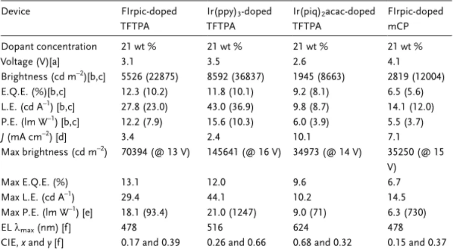
Table 1. Summary of device performance.
Device FIrpic-doped TFTPA Ir(ppy)3-doped TFTPA Ir(piq)2acac-doped TFTPA FIrpic-doped mCP Dopant concentration 21 wt % 21 wt % 21 wt % 21 wt % Voltage (V)[a] 3.1 3.5 2.6 4.1 Brightness (cd m–2)[b,c] 5526 (22875) 8592 (36837) 1945 (8663) 2819 (12004) E.Q.E. (%)[b,c] 12.3 (10.2) 11.8 (10.1) 9.2 (8.1) 6.5 (5.6) L.E. (cd A–1) [b,c] 27.8 (23.0) 43.0 (36.9) 9.8 (8.7) 14.1 (12.0) P.E. (lm W–1) [b,c] 12.2 (7.9) 15.6 (10.3) 6.0 (3.9) 5.5 (3.7) J (mA cm–2) [d] 3.4 2.4 10.1 7.1 Max brightness (cd m–2) 70394 (@ 13 V) 145641 (@ 16 V) 34973 (@ 14 V) 35250 (@ 15 V) Max E.Q.E. (%) 13.1 12.0 9.6 6.7 Max L.E. (cd A–1) 29.4 44.1 10.2 14.5
Max P.E. (lm W–1) [e] 18.1 (93.4) 21.0 (1247) 9.0 (71) 6.3 (730)
EL kmax(nm) [f ] 478 516 624 478
CIE,x and y [f ] 0.17 and 0.39 0.26 and 0.66 0.68 and 0.32 0.15 and 0.37
[a] Recorded at 1 cd m–2. [b] Recorded at 20 mA cm–2. [c] The data in parentheses were
re-corded at 100 mA cm–2. [d] Current density at the brightness of 1000 cd m-2. [e] The data
in parentheses were the corresponding brightness (cd m-2). [f ] At 9 V.
P
ciencies of the Ir(piq)2acac-based
red-emitting devices. Similar to the behavior of the green-emitting devices, increasing the dopant concentration significantly re-duced the turn-on voltage, accompanied by a large enhancement in efficiency. The 21-wt %-doped device exhibited the high-est performance with an extremely low turn-on voltage (ca. 2.6 V); the maximum values of gext and gp reached as high as
9.6 % (10.2 cd A–1, 2.75 mA cm–2) and
9.0 lm W–1, respectively. We note that the peak power efficiency of the TFTPA-based device was approximately three times higher than that of the CBP-based devices (ca. 3 lm W–1) at the optimized
dopant concentration (ca. 7 wt %).[28] Furthermore, our red-emitting devices exhibited a much reduced degree of effi-ciency roll-off at high brightness. The ex-ternal quantum efficiency and power effi-ciency of our 21-wt %-Ir(piq)2acac-doped
Figure 5. AFM topographic images (tapping mode) of the 21 %-FIrpic-doped a) TFTPA and
b) mCP films. Films were vapor-deposited onto silicon wafers under vacuum.
0 2 4 6 8 10 12 14 16 18 20 22 24 0 100 200 300 400 500 600 700 800 900 1000 10000 100000 Ir(ppy)3( 7 %) Ir(ppy)3 (14 %) Ir(ppy) 3 (21 %) Voltage (V) Br ig htn ess (cd m -2 ) Current Density ( m A cm -2 ) 0 20 40 60 80 100 120 140 160 180 200 0.1 1 10 Ir(ppy)3 ( 7 %) Ir(ppy) 3 (14 %) Ir(ppy)3 (21 %) Ext e rnal Qu a n tu m Eff ici en c y (% ) 0.1 1 10 100
Current Density (mA cm-2)
Power Ef fi ci ency ( lm W -1 ) (b) (a)
Figure 6. a) Current density (open symbols) and brightness (solid
sym-bols) plotted as a function of the voltage and b) the external quantum effi-ciency and power effieffi-ciency plotted as a function of the current density for the Ir(ppy)3-doped TFTPA devices at various doping concentrations.
0 2 4 6 8 10 12 14 16 18 0 100 200 300 400 500 600 700 800 900 1000 1100 Ir(piq) 2acac ( 7 %) Ir(piq) 2acac (14 %) Ir(piq) 2acac (21 %) Voltage (V) B rightness (cd m -2 ) C u rr ent D e n s ity (m A cm -2 ) 100 1000 10000 100000 0 20 40 60 80 100 120 140 160 180 200 0.1 1 10 E x te rnal Qu ant u m Eff ici e ncy (% ) 0.1 1 10 100 Ir(piq) 2acac ( 7 %) Ir(piq)2acac (14 %) Ir(piq)2acac (21 %)
Current Density (mA cm-2)
Pow e r Eff ici ency (l m W -1 ) (a) (b)
Figure 7. a) Current density (open symbols) and brightness (solid
sym-bols) plotted as function of the voltage and b) the external quantum effi-ciency and power effieffi-ciency plotted as a function of the current density for the Ir(piq)2acac-doped TFTPA devices at various doping concentrations.
FULL
P
TFTPA device at 100 cd m–2 were 9.3 % and 8.8 lm W–1, re-spectively; when we increased the brightness of this device up to the order of 1 × 10³cd m–2, the corresponding EL efficiencies remained above 9.2 % and 6.6 lm W–1, respectively, which are
among the best reported to date for red-emitting electrophos-phorescent devices based on Ir(piq)2acac and its
ana-logues.[29–31]
According to the I–V curve characteristics of the above three different color (R-G-B) device systems, an increase in the dop-ant concentration led to a decreasing drive voltage. This phe-nomenon indicates that the charges may be injected directly to the dopant molecules at high doping concentrations; these moi-eties then serve as an additional channel to transport charges by hopping between the dopant sites, with TFTPA acting as an inert host matrix.[5,32–35]In addition, when the dopant concen-tration is increased, the opportunity for carrier recombination at the dopant emitters might also increase, leading to a higher device efficiency. Consequently, we speculate that the pro-nounced enhancement of the device power efficiency at high doping concentrations arose from two contributing factors: the increased luminous efficiency and the lowered driving voltage. More importantly, the excellent performances of these blue-, green-, and red-emitting devices were obtained from simple de-vice architectures, which make them very attractive for com-mercial applications.
3. Conclusions
We have developed a facile synthetic route for the prepara-tion of a novel host material, TFTPA, which contains a TPA core with three 9-phenyl-9-fluorenyl groups attached at its per-ipheries. This one-step Friedel–Crafts-type reaction is not only simple but, because of the use of inexpensive reactants and mild operating conditions, it is also cost effective. Using this synthetic strategy, TFTPA can be produced readily on a large scale. Owing to the presence of the sterically bulky 9-phenyl-9-fluorenyl groups, TFTPA exhibits a high glass transition tem-perature (186 °C) and is morphologically and electrochemically stable. AFM measurements suggested that the aggregation of the triplet iridium dopant was depressed significantly when
TFTPA was used as the host. As a result, self-quenching is
ef-fectively reduced leading to highly efficient phosphorescent de-vices at high dopant concentrations (optimized at 21 wt %). The performance of the TFTPA-based devices is far superior to those of the corresponding mCP- or CBP-based devices, par-ticularly in the blue- and red-emitting electrophosphorescent device systems. The efficiencies of the blue-emitting device reached 12 % (26 cd A–1) and 18 lm W–1at a practical bright-ness of 100 cd m–2; these values are among the highest ever re-ported for blue electrophosphorescent devices. In addition, the red-emitting device exhibited an extremely low turn-on voltage (2.6 V) and a threefold enhancement in the power efficiency (9.0 lm W–1) relative to those of reference devices based incor-porating CBP as the host material. As well as yielding highly efficient full-color phosphorescence, our present approach should be attractive for the development of commercial
appli-cations because the simple device structure promises low-cost manufacturing.
4. Experimental
General Procedures:1H and13C NMR spectra were recorded on a Bruker-DRX 300 (300 MHz) spectrometer. Mass spectra were ob-tained using a Finnigan/Thermo Quest MAT 95XL mass spectrometer. Differential scanning calorimetry (DSC) was performed using a Seiko Exstar 6000DSC instrument operated at heating and cooling rates of 20 and 40 °C min–1, respectively. Samples were scanned from 30 to 420 °C, cooled to 0 °C, and then heated again to 420 °C; the glass transition temperature (Tg) was determined from the second heating scan.
Ther-mogravimetric analysis (TGA) was undertaken using a DuPont TGA 2950 instrument. The thermal stability of the samples under a nitrogen atmosphere was determined by measuring their mass loss while heating at a rate 20 °C min–1. UV-vis spectra were measured using an HP 8453 diode-array spectrophotometer. PL spectra were obtained using a Hita-chi F-4500 luminescence spectrometer. Cyclic voltammetry (CV) mea-surements were performed using a BAS 100 B/W electrochemical ana-lyzer operated at a scan rate of 100 mV s–1; the samples were dissolved in anhydrous CH2Cl2containing 0.1Mtetrabutylammonium
hexafluo-rophosphate (TBAPF6) as the supporting electrolyte. The potentials
were measured against an Ag/Ag+(0.01
MAgNO3) reference electrode,
using ferrocene as the internal standard. Atomic force microscopy measurements were performed in the tapping mode under ambient conditions using a Digital Nanoscope IIIa instrument.
Tris[4-(9-phenylfluoren-9-yl)phenyl]amine (TFTPA): CF3SO3H
(1.64 g, 10.9 mmol) was added dropwise at 25 °C under a nitrogen at-mosphere to a solution of triphenylamine (1.00 g, 4.08 mmol) and 9-phenyl-9-fluorenol (3.26 g, 12.6 mmol) in 1,4-dioxane (50 mL). The mixture was stirred under nitrogen at 80 °C; as the reaction proceeded, a white precipitate appeared because of the insolubility of TFTPA. After 3 h, the mixture was cooled to room temperature; the precipitate was filtered, washed with acetone (2 × 25 mL), and dried to provide a crude product, which was purified by repeated (two times) vacuum sublimation to yield ultrapure TFTPA as a white solid (3.9 g, 72.0 %).
1H NMR (CDCl 3, 300 MHz): d 7.79 (d, J = 7.5 Hz, 6H), 7.36–7.45 (m, 12H), 7.23–7.33 (m, 21H), 7.05 (d, J = 8.6 Hz, 6H), 6.89 (d, J = 8.6 Hz, 6H). 13C NMR (CDCl 3, 75 MHz): d151.3, 146.0, 145.8, 140.0, 139.7, 128.8, 128.1, 128.0, 127.6, 127.4, 126.5, 126.2, 123.5, 120.1, 64.9. HRMS [M + H]+: calcd. for C75H52N 966.4101, found 966.4106. Anal. Calcd.
for C75H51N: C, 93.23; H, 5.32; N, 1.45. Found: C, 92.91; H, 5.46; N,
1.40.
Received: February 14, 2007 Revised: April 11, 2007 Published online: August 28, 2007
–
[1] T. Fuhrmann, J. Salbeck, MRS Bull. 2003, 28, 354.
[2] M. A. Bado, D. F. O’Brien, Y. You, A. Shoustikov, S. Sibley, M. E. Thompson, S. R. Forrest, Nature 1998, 395, 151.
[3] S. Lamansky, P. Djurovich, D. Murphy, F. Abdel-Razzaq, H. E. Lee, C. Adachi, P. E. Burrows, S. R. Forrest, M. E. Thompson, J. Am.
Chem. Soc. 2001, 123, 4304.
[4] N. J. Turro, Modern Molecular Photochemistry, University Science Books, Sausalito, CA 1991.
[5] C. Adachi, M. A. Baldo, M. E. Thompson, S. R. Forrest, J. Appl.
Phys. 2001, 90, 5048.
[6] Y. Kawamura, K. Goushi, J. Brooks, J. J. Brown, H. Sasabe, C. Ada-chi, Appl. Phys. Lett. 2005, 86, 071 104.
[7] M. H. Tsai, Y. H. Hong, C. H. Chang, H. C. Su, C. C. Wu, A. Mato-liukstyte, J. Simokaitiene, S. Grigalevicius, J. V. Grazulevicius, C. P. Hsu, Adv. Mater. 2007, 19, 862.
[8] R. J. Holmes, S. R. Forrest, Y.-J. Tung, R. C. Kwong, J. J. Brown, S. Garon, M. E. Thompson, Appl. Phys. Lett. 2003, 82, 2422.
P
[9] S.-J. Yeh, M.-F. Wu, C.-T. Chen, Y.-H. Song, Y. Chi, M.-H. Ho, S.-F. Hsu, C. H. Chen, Adv. Mater. 2005, 17, 285.
[10] M.-H. Tsai, H.-W. Lin, H.-C. Su, T.-H. Ke, C.-C. Wu, F.-C. Fang, Y.-L. Liao, K.-T. Wong, C.-I. Wu, Adv. Mater. 2006, 18, 1216.
[11] K. Brunner, A. van Dijken, H. Borner, J. J. A. M. Bastiaansen, N. M. M. Kiggen, B. M. W. Langeveld, J. Am. Chem. Soc. 2004, 126, 6035.
[12] T. F. Palmer, S. S. Parmar, J. Photochem. 1985, 31, 273. [13] C.-L. Chiang, C.-F. Shu, Chem. Mater. 2002, 14, 682.
[14] H. Z. Xie, M. W. Liu, O. Y. Wang, X. H. Zhang, C. S. Lee, L. S. Hung, S. T. Lee, P. F. Teng, H. L. Kwong, H. Zheng, C. M. Che, Adv.
Mater. 2001, 13, 1245.
[15] S. Chew, C. S. Lee, S. T. Lee, P. Wang, J. He, W. Li, J. Pan, X. Zhang, H. Kwong, Appl. Phys. Lett. 2006, 88, 093 510.
[16] T. Ohta, K. Shudo, T. Okamoto, Tetrahedron Lett. 1983, 24, 71. [17] K.-T. Wong, Z.-J. Wang, Y.-Y. Chien, C.-L. Wang, Org. Lett. 2001, 3,
2285.
[18] P.-I. Shih, C.-L. Chiang, A. K. Dixit, C.-K. Chen, M.-C. Yuan, R.-Y. Lee, C.-T. Chen, E. W.-G. Diau, C.-F. Shu, Org. Lett. 2006, 8, 2799. [19] K. Katsuma, Y. Shirota, Adv. Mater. 1998, 10, 223.
[20] E. T. Seo, R. F. Nelson, J. M. Fritsch, L. S. Marcoux, D. W. Leedy, R. N. Adams, J. Am. Chem. Soc. 1966, 88, 3498.
[21] N. Nijegorodov, P. V. C. Luhanga, J. S. Nkoma, D. P. Winkoun,
Spec-trochim. Acta Part A 2006, 64, 1.
[22] S. Tokito, T. Iijima, Y. Suzuri, H. Kita, T. Tsuzuki, F. Sato, Appl. Phys.
Lett. 2003, 83, 569.
[23] I. Tanaka, Y. Tabata, S. Tokito, Chem. Phys. Lett. 2004, 400, 86. [24] F.-I. Wu, P.-I. Shih, M.-C. Yuan, A. K. Dixit, C.-F. Shu, Z.-M. Chung,
E. W.-G. Diau, J. Mater. Chem. 2005, 15, 4753.
[25] P. A. Vecchi, A. B. Padmaperuma, H. Qiao, L. S. Sapochak, P. E. Bur-rows, Org. Lett. 2006, 8, 2799.
[26] M. A. Baldo, C. Adachi, S. R. Forrest, Phys. Rev. B 2000, 62, 10 967. [27] M. A. Baldo, S. Lamansky, P. E. Burrows, M. E. Thompson, S. R.
For-rest, Appl. Phys. Lett. 1995, 75, 4.
[28] Y. J. Su, H. L. Huang, C. L. Li, C. H. Chien, Y. T. Tao, P. T. Chou, S. Datta, R. S. Liu, Adv. Mater. 2003, 15, 884.
[29] A. Tsuboyama, H. Iwawaki, M. Furugori, T. Mukaide, J. Kamatani, S. Igawa, T. Moriyama, S. Miura, T. Takiguchi, S. Okada, M. Hoshino, K. Ueno, J. Am. Chem. Soc. 2003, 125, 12 971.
[30] C. H. Yang, C. C. Tai, I. W. Sun, J. Mater. Chem. 2004, 14, 947. [31] X. Yang, D. C. Müller, D. Neher, K. Meerholz, Adv. Mater. 2006, 18,
948.
[32] Y. L. Tung, S. W. Lee, Y. Chi, L. S. Chen, C. F. Shu, F. I. Wu, A. J. Carty, P. T. Chou, S. M. Peng, G. H. Lee, Adv. Mater. 2005, 17, 1059. [33] Y. Y. Noh, C. L. Lee, J. J. Kim, J. Chem. Phys. 2003, 118, 2853. [34] R. J. Holmes, B. W. D’Andrade, S. R. Forrest, X. Ren, J. Li, M. E.
Thompson, Appl. Phys. Lett. 2003, 83, 3818.
[35] Y. L. Tung, L. S. Chen, Y. Chi, P. T. Chou, Y. M. Cheng, E. Y. Li, G. H. Lee, C. F. Shu, F. I. Wu, A. J. Carty, Adv. Funct. Mater. 2006,
16, 1615.