Shot noise of quantum ring excitons in a planar microcavity
Y. N. Chen, D. S. Chuu, and S. J. ChengDepartment of Electrophysics, National Chiao-Tung University, Hsinchu 300, Taiwan
共Received 25 July 2005; revised manuscript received 5 September 2005; published 1 December 2005兲
Shot noise of quantum ring共QR兲 excitons in a p-i-n junction surrounded by a microcavity is investigated theoretically. Some radiative decay properties of a QR exciton in a microcavity can be obtained from the observation of the current noise, which also gives extra information about one of the tunnel barriers. A different noise feature between the quantum dot 共QD兲 and QR is pointed out, and may be observed in a suitably designed experiment.
DOI:10.1103/PhysRevB.72.233301 PACS number共s兲: 71.35.⫺y, 73.63.⫺b, 73.50.Td, 42.50.Pq
Since Purcell proposed the idea of controlling the sponta-neous emission rate by using a cavity,1 the enhanced and inhibited SE rate for the atomic system was intensively in-vestigated in the 1980s2 by using atoms passed through a cavity. In semiconductor systems, the electron-hole pair is naturally a candidate to examine the spontaneous emission. Modifications of the SE rates of the quantum dot 共QD兲,3 quantum wire,4 or quantum well5 excitons inside the micro-cavities have been observed experimentally.
Interest in measurements of shot noise spectrum has risen owing to the possibility of extracting valuable information not available in conventional dc transport experiments.6With the advances of fabrication technologies, it is now possible to embed the QDs inside a p-i-n structure7 such that the electron and hole can be injected separately from opposite sides. This allows one to examine the exciton dynamics in a QD via electrical currents.8 On the other hand, it is now possible to fabricate the ring-shaped dots of InAs in GaAs with a circumference of several hundred nanometers.9 Opti-cal detection of the Aharonov-Bohm effect on an exciton in a single quantum ring共QR兲 was also reported.10
Based on the rapid progress of nanotechnologies, it is not hard to imagine that the QR can be incorporated in a p-i-n junction surrounded by the microcavity. Examinations of the dynamics of the QR excitons by the electrical currents can be realized. We thus present in this work the nonequilibrium calculations of such a device. Current noise of QR excitons in a planar microcavity is obtained via the MacDonald formula11and is found to reveal some characteristics of the restricted environment, i.e., the density of states of the con-fined photons.
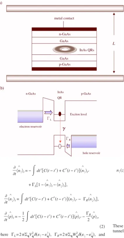
The model. Consider now a QR embedded in a p-i-n
junc-tion as shown in Fig. 1. Both the hole and electron reservoirs are assumed to be in thermal equilibrium. For the physical phenomena we are interested in, the Fermi level of the
p共n兲-side hole 共electron兲 is slightly lower 共higher兲 than the
hole共electron兲 subband in the dot. After a hole is injected into the hole subband in the QR, the n-side electron can tunnel into the exciton level because of the Coulomb inter-action between the electron and hole. Thus, we may intro-duce the three ring states; 兩0典=兩0,h典, 兩↑典=兩e,h典, and 兩↓典=兩0,0典, where 兩0,h典 means there is one hole in the QR, 兩e,h典 is the exciton state, and 兩0, 0典 represents the ground state with no hole and electron in the QR. One might argue
that one cannot neglect the state兩e,0典 for real device since the tunable variable is the applied voltage. This can be re-solved by fabricating a thicker barrier on the electron side so that there is little chance for an electron to tunnel in advance. Moreover, the charged exciton and biexcitons states are also neglected in our calculations. This means a low injection limit is required in the experiment.7
Derivation of a master equation. We can now define the
ring-operators nˆ ⬅兩↑典具↑兩, n↑ ˆ ⬅兩↓典具↓兩, pˆ⬅兩↑典具↓兩, s↓ ˆ↑
⬅兩0典具↑兩, sˆ ⬅兩0典具↓兩. The total Hamiltonian H of the system↓ consists of three parts; H0 关ring, photon bath Hp, and the electron 共hole兲 reservoirs Hres兴, HT 共ring-photon coupling兲, and the ring-reservoir coupling HV
H = H0+ HT+ HV, H0=↑n ∧ ↑+↓n ∧ ↓+ Hp+ Hres, HT=
兺
k 共Dkbk†p ∧ + Dk*bkp ∧ †兲 = p∧X + p∧†X†, Hp=兺
k kbk†bk, HV=兺
q 共Vqcq † s ∧ ↑+ Wqdq † s ∧ ↓+ c.c.兲, Hres=兺
q q↑cq†cq+兺
q q↓dq†dq. 共1兲 In the above equation, bkis the photon operator, Dk is the dipole coupling strength, X =兺kDkbk†
, and cq and dq denote the electron operators in the left and right reservoirs, respec-tively. The couplings to the electron and hole reservoirs are given by the standard tunnel Hamiltonian HV, where Vqand Wqcouple the channels q of the electron and the hole reser-voirs. If the couplings to the electron and the hole reservoirs are weak, then it is reasonable to assume that the standard Born-Markov approximation with respect to these couplings is valid. In this case, one can derive a master equation from the exact time evolution of the system. The equations of motion can be expressed as共cf. Ref. 12兲
PHYSICAL REVIEW B 72, 233301共2005兲
t具n ∧ ↑典t= −
冕
dt⬘
关C共t − t⬘
兲 + C*共t − t⬘
兲兴具n ∧ ↑典t⬘ +⌫L关1 − 具n ∧ ↑典t−具n ∧ ↓典t兴, t具n ∧ ↓典t=冕
dt⬘
关C共t − t⬘
兲 + C*共t − t⬘
兲兴具n ∧ ↑典t⬘−关⌫R具n ∧ ↓典t兴, t具p ∧ 典t= − 1 2冕
dt⬘
关C共t − t⬘
兲 + C *共t − t⬘
兲兴具p∧典 t⬘− ⌫R 2 具p ∧ 典t, 共2兲 where ⌫L= 2兺qVq2␦共↑−q↑兲, ⌫R= 2兺qWq2␦共↓−q↓兲, and =↑−↓ is the energy gap of the QR exciton. Here,C共t−t
⬘
兲⬅具XtXt⬘ †典0is the photon correlation function, and de-pends on the time interval only. We can now define the Laplace transformation for real z,
C共z兲 ⬅
冕
0 ⬁ dte−zteitC共t兲, n↑共z兲 ⬅冕
0 ⬁ dte−zt具n ∧ ↑典tetc., z⬎ 0, 共3兲 and transform the whole equations of motion into z space,n↑共z兲 = − 关C共z兲 + C*共z兲兴n↑共z兲/z +⌫L z 关1/z − n↑共z兲 − n↓共z兲兴, n↓共z兲 = 关C共z兲 + C*共z兲兴n↓共z兲/z −⌫R z n↓共z兲, p共z兲 = −1 2关C共z兲 + C *共z兲兴p共z兲/z −⌫R 2zp共z兲. 共4兲 These equations can then be solved algebraically, and the tunnel current from the hole- or electron-side barrier
I ∧ R= − e⌫R具n ∧ ↓典t, I ∧ L= − e⌫L关1 − 具n ∧ ↑典t−具n ∧ ↓典t兴 共5兲 can then be obtained by performing the inverse Laplace transformation on Eqs.共4兲.
Shot noise spectrum. In a quantum conductor in
nonequi-librium, electronic current noise originates from the dynami-cal fluctuations of the current being away from its average. To study correlations between carriers, we relate the exciton dynamics with the hole reservoir operators by introducing the degree of freedom n as the number of holes that have tunneled through the hole-side barrier13and write
FIG. 1. 共Color online兲 共a兲 Schematic descrip-tion of a QR inside a p-i-n juncdescrip-tion surrounded by a planar microcavity with length L. 共b兲 Energy-band diagram of a QR in the p-i-n junction.
BRIEF REPORTS PHYSICAL REVIEW B 72, 233301共2005兲
n˙0共n兲共t兲 = − ⌫Ln0共n兲共t兲 + ⌫Rn↓共n−1兲共t兲,
n˙↑共n兲共t兲 + n˙↓共n兲共t兲 = 共⌫L−⌫R兲n0共n兲共t兲. 共6兲 Equation共6兲 allows us to calculate the particle current and the noise spectrum from Pn共t兲=n0共n兲共t兲+n↑共n兲共t兲+n↓共n兲共t兲 which gives the total probability of finding n electrons in the col-lector by time t. In particular, the noise spectrum SIR can be calculated via the MacDonald formula.14 In the zero-frequency limit, the Fano factor can be written as
F⬅ SIR共= 0兲 2e具I典 = 1 −
冏
A共z兲⌫L⌫R关A共z兲 + 2共⌫L+⌫R兲兴 兵A共z兲⌫R+⌫L关A共z兲 + 2⌫R兴其2冏
z=0 , 共7兲 where A共z兲⬅C共z兲+C*共z兲.Results and Discussions. From Eq.共7兲, one knows that the
noise spectrum of the QR excitons depends strongly on
C共z兲, which reduces to the radiative decay rate ␥ in the Markovian limit. The exciton decay rate␥ in a microcavity can be obtained easily from the perturbation theory and is given by ␥= e 2ប m2c d
冕
兩H0 共1兲 ⫻共q⬘
兲兩2q⬘
冉
兺
kz⬘ ␦共 − c冑
q⬘
2+ kz⬘
2兲冑
kz⬘
2+ q⬘
2 兩⑀q⬘k z ⬘·兩2冊
dq⬘
, 共8兲 whereis the ring radius, d is the lattice spacing, H0共1兲is the Hankel function,⑀q⬘kz
⬘is the polarization of the photon, and is the dipole moment of the QR exciton.15The summation of the integer modes in the kz
⬘
direction is determined from the boundary conditions of the planar microcavity.The radiative decay rate␥of a QR exciton inside a planar microcavity is numerically displayed in the inset of Fig. 2. The tunneling rates,⌫L and⌫R, are assumed to be equal to 0.1␥0and␥0, where␥0共⬃1/1 ns兲 is the decay rate of a QR
exciton in free space. Also, the planar microcavity is as-sumed to have a Lorentzian broadening at each resonant mode共with broadening width equal to 1% of each resonant mode兲.16 As the cavity length is shorter than one half the wavelength of the emitted photon共L⬍0/ 2兲, the decay rate is inhibited because of the cut-off frequency of the cavity. When the cavity length exceeds some multiple wavelength, it opens up another decay channel for the quantum ring exciton and turns out that there is an abrupt enhancement on the decay rate. Such a singular behavior also happens in the decay of one dimensional quantum wire polaritons inside a microcavity.16 This is because the ring geometry preserves the angular momentum of the exciton, rendering the forma-tion of exciton-polariton in the direcforma-tion of circumference. This kind of behavior can also be found in the calculations of a Fano factor as demonstrated by the solid line in Fig. 2. Comparing to the zero-frequency noise of the QD excitons 共dashed line兲, the Fano factor of the QR excitons shows the “cusp” feature at each resonant mode.
Another interesting point is that below the lowest resonant mode共L=0/ 2兲, both the solid and dashed curves have a dip in the Fano factor. It is not seen from the radiative decay rate. To answer this, we have plotted Eq.共7兲 in Fig. 3 as a func-tion of the decay rate␥. Keeping ⌫R unchanged, the solid, dashed, and dashed-dotted lines correspond to the electron-side tunneling rate ⌫L= 0.01␥0, 0.5␥0, and 0.1␥0, respec-tively. As can be seen, the Fano factor has a minimum point at␥=⌫L⌫R共⌫L+⌫R兲/共⌫L2+⌫R2兲. Comparing this with the inset of Fig. 2, one immediately knows that when the cavity length is increased to0/ 2, the abruptly increased decay rate will cross the minimum point and result in a dip in Fig. 2. Fur-thermore, in the limit of⌫RⰇ⌫L, the minimum point can be approximated as␥⬇⌫L. This means by observing the dip in the Fano factor of Fig. 2, the magnitude of the electron-side tunneling rate⌫Lcan be obtained.
To further understand the difference between the QD and QR excitons, Fig. 4 illustrates the shot noise as a function of energy gap. In plotting the figure, a perfect planar micro-cavity is assumed for convenience. As can be seen, the shot noise of the QD excitons shows the plateau feature 共solid line兲 with the increasing of , while it is a zigzag behavior
FIG. 2. Fano factor as a function of cavity length L. The vertical and horizontal units are关SI
R共0兲兴/共2eI兲 and 0/ 2, respectively. The
inset shows the radiative decay rate of a QR exciton in a planar microcavity.
FIG. 3. Fano factor as a function of the decay rate for different electron-side tunneling rate⌫L= 0.01␥0共solid line兲, 0.05␥0共dashed
line兲, and 0.1␥0共dashed-dotted line兲. The hole-side tunneling rate is fixed共⌫R=␥0兲.
BRIEF REPORTS PHYSICAL REVIEW B 72, 233301共2005兲
共gray-dashed and dashed-dotted lines兲 for the QR excitons. This is because the decay rate of the QD exciton in a micro-cavity is given by16 ␥dot⬀
兺
nc e2ប m2c2L关共/បc兲 2−共n c/L兲2兴兩⑀q⬘k z ⬘·兩2, 共9兲 where is the step function, and the summation is over the positive integers. Therefore, when the energy gap is tuned above some resonant mode of the cavity, the decay rate is a constant before the next decay channel is opened. On the other hand, however, one knows that the decay rate for the QR exciton is not a constant between two resonant modes. This explains why the decay property for QR exciton is dif-ferent from that for the QD exciton under the same photonic environment, and the difference may be distinguished by the shot noise measurements. From the experimental point ofview, different dependences on are easier to be realized since it is almost impossible to vary the cavity length once the sample is prepared. A possible way to observe the men-tioned effects is to vary around the discontinuous points and measure the corresponding current noise.
A few remarks about the ring radius should be mentioned here. One should note that we do not give the specific value of the ring radius in our model. Instead, a phenomenological value about the free space decay rate␥0is used. The magni-tudes of the tunnel rates are set relative to it. In general, the changing of radius will certainly affect the shot noise. For example, because of the exciton-polariton共super radiant兲 ef-fect in the direction of circumference, an increasing of ring radius will enhance the decay rate. In addition, the dipole moment of the QR exciton is also altered because of the varying of the wave function. All these can contribute to the variations of the decay rate and shot noise. In our previous study,15 we have shown that the decay rate is a monotonic increasing function on radius if the exciton is coherent in the quantum ring, i.e., free of scattering from impurities or imperfect boundaries. The dashed-dotted line in Fig. 4 shows the result for doubled free-space decay rate, i.e., ␥0→2␥0. Although the noise is increased, the zigzag feature remains unchanged.
In conclusion, we have derived in this work the nonequi-librium current noise of QR excitons incorporated in a p-i-n junction surrounded by a planar microcavity. Some radiative decay properties of the one-dimensional QR exciton can be obtained from the observation of shot noise spectrum, which also shows extra information about the electron-side tunnel-ing rate. Different noise features between the QD and QR are pointed out, and deserve to be tested with present technolo-gies.
This work is supported partially by the National Science Council, Taiwan under Grant Nos. NSC 94-2112-M-009-019 and NSC 94-2120-M-009-002.
1E. M. Purcell, Phys. Rev. 69, 681共1946兲.
2P. Goy et al., Phys. Rev. Lett. 50, 1903共1983兲; G. Gabrielse and
H. Dehmelt, ibid. 55, 67共1985兲; R. G. Hulet et al., ibid. 55, 2137共1985兲; D. J. Heinzen et al., ibid. 58, 1320 共1987兲.
3J. M. Gerard et al., Phys. Rev. Lett. 81, 1110共1998兲; M. Bayer et al., ibid. 86, 3168共2001兲; G. S. Solomon et al., ibid. 86, 3903
共2001兲.
4C. Constantin et al., Phys. Rev. B 66, 165306共2002兲.
5G. Bjork et al., Phys. Rev. A 44, 669共1991兲; K. Tanaka et al.,
Phys. Rev. Lett. 74, 3380共1995兲.
6C. W. J. Beenakker, Rev. Mod. Phys. 69, 731 共1997兲; Y. M.
Blanter and M. Buttiker, Phys. Rep. 336, 1共2000兲.
7Z. Yuan et al., Science 295, 102共2002兲; G. Kießlich et al., Phys.
Rev. B 68, 125331共2003兲.
8Y. N. Chen et al., Phys. Rev. B 69, 245323共2004兲.
9R. J. Warburton et al., Nature共London兲 405, 926 共2000兲. 10M. Bayer et al., Phys. Rev. Lett. 90, 186801共2003兲. 11D. K. C. MacDonald, Rep. Prog. Phys. 12, 56共1948兲.
12T. Brandes and B. Kramer, Phys. Rev. Lett. 83, 3021共1999兲; Y.
N. Chen et al., ibid. 90, 166802共2003兲.
13Actually, the total current noise should be expressed in terms of
the spectra of particle currents and the charge noise spectrum:
SI共兲=aSI
L共兲+bSIR共兲−ab
2S
Q共兲, where a and b are
capaci-tance coefficient共a+b=1兲 of the junctions. Since we have as-sumed a highly asymmetric set up 共aⰆb兲, it is plausible to consider the hole-side spectra SIR共兲 only.
14R. Aguado and T. Brandes, Phys. Rev. Lett. 92, 206601共2004兲. 15Y. N. Chen and D. S. Chuu, Solid State Commun. 130, 491
共2004兲.
16Y. N. Chen et al., Phys. Rev. B 64, 125307共2001兲.
FIG. 4. Fano factor of QD共solid line兲 and QR 共gray dashed line兲 excitons as a function of energy gap. The vertical and horizontal units are关SIR共0兲兴/共2eI兲 and 2hc/0, respectively. The dashed-dotted
line represents that if the free-space decay rate of the QR exciton is enhaced by a factor of 2共␥0→2␥0兲, the shot noise is also enhanced.
BRIEF REPORTS PHYSICAL REVIEW B 72, 233301共2005兲