國立交通大學
資訊學院 資訊學程
碩士論文
一個無線區域網路上
之高效率
媒體串流輪詢
機制
A Highly Efficient Polling Scheme for Media
Streaming on Wireless LANs
研 究 生 : 宋朝宗
指導教授 : 陳耀宗 教授
一個無線區域網路上之高效率媒體串流輪詢機制
A Highly Efficient Polling Scheme for Media
Streaming on Wireless LANs
研 究 生 : 宋朝宗
Student : Chao-Tsung Sung
指導教授 : 陳耀宗
Advisor : Yaw-Chung Chen
國 立 交 通 大 學
資訊學院 資訊學程
碩 士 論 文
A Thesis
Submitted to College of Computer Science National Chiao Tung University in partial Fulfillment of the Requirements
for the Degree of Master of Science
in
Computer Science August 2007
Hsinchu, Taiwan, Republic of China
一個無線區域網路上之高效率媒體串流輪詢機制
學生 : 宋朝宗 指導教授 : 陳耀宗 教授 國立交通大學 資訊學院 資訊學程摘 要
IEEE 802.11e標準是為了增進無線區域網路上的語音和多媒體服務品質(QoS)而制 定。它在HCF控制型通道存取(HCCA)模式中提出一個參考排程器來管理輪詢的順序。然 而,這個排程器在大量多媒體資料傳輸負荷下,可能會大大的降低傳輸量及增加延遲時 間,這是因為它所使用的輪詢機制可能造成一些不必要的傳輸額外負擔。為了要減少傳 輸時間的延遲以及輪詢的額外負擔,在這篇論文中,我們提出了一個高效率輪詢機制來 提升HCCA模式的服務品質。這個輪詢機制是基於每個工作站下一次被預估輪詢的時間的 間隔,因此我們提出的策略是每次都以最早預估資料抵達時限的工作站為優先,以改善 原先輪流輪詢機制可能遇到被輪詢的工作站無資料可送時,所造成頻寬的浪費。同時, 由於一個無線存取點所支援工作站的數量是有限的,我們利用了最直接的線性搜尋方式 以找出下一個被輪詢的目標,如此大大地降低了實作上的複雜度。此外,為了可以更正 確地偵測出工作站的資料流間隔,這個新的機制利用工作站回傳的資料訊框中QoS欄 位,讓混合式協調者可以更準確的調整下次輪詢的時間。而且新的機制亦會根據語音資 料的特性,動態地調整傳輸資料流的服務間隔。從模擬的結果可以清楚的看到,我們所 提出的方法與標準802.11e輪詢方式相比可以有效地減少傳輸延遲時間與抖動率,並提 升整體傳輸量。 關鍵詞 : 無線區域網路,服務品質,混合協調機制,HCF 控制型通道存取,線性搜尋。A Highly Efficient Polling Scheme for Media
Streaming on Wireless LANs
Student: Chao-Tsung Sung Advisor: Yaw-Chung Chen Degree Program of Electrical Engineering and Computer Science
National Chiao Tung University
Abstract
IEEE 802.11e specification was established for improving the quality of service (QoS) issues in voice and multimedia over wireless LANs (WLANs). In the HCF Controlled Channel Access (HCCA) mode, it offered a reference scheduler that maintains a polling list. However, under a high load of multimedia transmissions, this reference scheduler may encounter decreasing of throughput and increasing of latency. This is because the polling scheme it used usually causes some overhead in doing unnecessary polling. In order to reduce access delays and polling overhead, as well as to improve the throughput of the channel, in this thesis, we proposed a highly efficient polling scheme to provide better QoS in the HCCA mode. Our polling scheme is based on the intervals in estimated polling time of each traffic stream, for the reason, our strategy is to poll the station with earliest-due-date-first discipline, instead as in the round-robin polling of reference scheduler. Our scheme minimizes the waste of bandwidth when the polled stations have no data frame to send. In the mean time, due to the limited number of client stations under the coverage of an access point, we use the linear search to find the next target to be polled, so that the implementation complexity is greatly reduced. Besides, for precisely detecting the dataflow interval for traffic steams, we use the QoS control field of data frame sent from stations, Hybrid Coordinator (HC) could use this collected information to adjust the estimated polling time. Further, our scheme could dynamically adjust the service interval of voice transmission according the characteristics of voice flow. The simulation results show that our proposed scheme can reduce transmission
latency and jitter as well as total throughput in comparing with the reference polling scheme in the IEEE 802.11e standard.
誌 謝
這篇論文的完成,首先我最想感謝的是我的指導教授 陳耀宗老師,在這兩年的研 究所生涯,由於其豐富的學術涵養以及熱心的指導,使我獲益良多;還有多媒體實驗室 的學長學弟們,感謝你們在這些日子的指教與協助,這段日子將是我美好的回憶。最後, 我要感謝的是我的家人,由於你們的默默支持與鼓勵,使我能夠堅持完成這篇論文。謝 謝你們。Table of Contents
中文提要
... iAbstract... ii
誌謝
... ivList of Figures... vi
List of Tables... vii
Chapter 1 Introduction...…. 1
Chapter 2 Background and Related Work...…. 5
2.1 Review of IEEE 802.11 MAC... 5
2.1.1 Distributed Coordination Function... 6
2.1.2 Point Coordination Function... 7
2.2 Introduction to IEEE 802.11e... 9
2.2.1 Enhanced Distributed Channel Access (EDCA)…... 9
2.2.2 The procedure of QoS flow setup…... 12
2.2.3 HCF Controlled Channel Access (HCCA)…... 13
2.3 Comparison between WLAN MACs... 16
2.4 Multimedia traffic attributes………... 17
2.5 Related Works... 18
Chapter 3 Proposed Scheme... 20
3.1 Main Architecture... 21
3.2 Structure of Polling List... 23
3.2.1 The format of Polling List…... 23
3.2.2 The maintenance of Polling List…... 25
3.3 Polling Mechanism... 26
3.3.1 Highly Efficient Polling Scheme... 28
3.3.2 Dynamic adjustment of estimated polling time... 30
3.4 Silence Detection Handling…….……... 31
Chapter 4 Simulations and Numerical Results... 36
4.1 Simulation model... 36
4.2 Simulation results... 37
4.2.1 Throughput... 37
4.2.2 Access Delay... 40
4.2.3 Delay jitter……... 40
Chapter 5 Conclusion and Future Work... 42
References... 44
List of Figures
Figure 2.1: IEEE 802.11 MAC architecture……….………... 5
Figure 2.2: DCF transmission scheme…………... 6
Figure 2.3: DCF timing sequence... 7
Figure 2.4: PCF timing sequence…………... 8
Figure 2.5: IEEE 802.11e MAC architecture…... 9
Figure 2.6: Reference implementation model of EDCA... 10
Figure 2.7: IFS relationship and related terms………... 11
Figure 2.8: TSPEC element format……….…………... 12
Figure 2.9: The sequence of message occurring at a traffic stream setup... 13
Figure 2.10: An example of 802.11e beacon interval used in HCCA…………... 14
Figure 3.1: Architecture of the proposed scheme………... 22
Figure 3.2: IEEE 802.11e reference RR polling scheme…………... 28
Figure 3.3: The HEP polling scheme…………... 30
Figure 3.4: An issue of start time of estimated polling…………... 30
Figure 3.5: The frame generating procedure of QSTA…..………... 31
Figure 3.6: Proposed talk-spurt and silence detection method…..………... 33
Figure 3.7: The effect in using proposed silence handler..………... 33
Figure 3.8: The effect in using proposed silence handler with fast-recover method... 34
Figure 4.1: The simulation topology... 36
Figure 4.2: The relationship of total throughput and network load... 38
Figure 4.3: Throughput against network size of RR, and two types of HEP schedulers.. 39
Figure 4.4: Average access delay of time sensitive traffics against number of QSTA... 40
Figure 4.5: Delay jitter between packets in RR polling scheme... 41
Figure 4.6: Delay jitter between packets in proposed scheme... 41
List of Tables
Table 1.1: The IEEE 802.11 family... 2
Table 2.1: The mapping between user priority and AC... 10
Table 2.2: QoS frames... 16
Table 2.3: Speech Codec standards... 17
Table 3.1: The comparison of polling schemes….…………...………..…………... 22
Table 3.2: The format of proposed polling list….…………...………..…………... 23
Table 4.1: Simulation parameters... 37
Table 4.2: Average throughput between two polling schemes….…………..…………... 39
List of Equations
Equation (1) ... 6 Equation (2) ... 11 Equation (3) ... 15 Equation (4) ... 26 Equation (5) ... 40Chapter 1
Introduction
Recently, several wireless communication protocols, such as WLAN, WiMAX, UWB, and Bluetooth were proposed for various applications. Among these protocols, the IEEE 802.11 WLAN is the most popular that provides wireless communication services. Wireless LAN (WLAN) supports high bandwidth with characteristics of easy installation and low cost, so it spreads quickly.
The IEEE 802.11 standard [1] is a large family, shown in Table 1.1. The original version was established by IEEE in 1997. In that time, it just supported 1 and 2Mbps transmission rates through three types of PHY medium, infrared (IR), frequency hopping spread spectrum radio (FHSS), and direct sequence spread spectrum radio (DSSS). The IEEE 802.11 provides two access functions in MAC sub-layer – Point Coordination Function (PCF) and Distributed Coordination Function (DCF). The PCF is a centralized mechanism, where a point coordinator (PC) sends CF-Poll frames to stations and allows it contention freely to transmit frames. The DCF is based on the carrier sense multiple access with collision avoidance (CSMA/CA) mechanism and allows the stations contend for the medium. In 1999, two extended standards were approved by IEEE working group. One is 802.11b that is based on DSSS, operating in 2.4 GHz with data rate up to 11Mbps; the other is 802.11a which is based on orthogonal frequency-division multiplexing (OFDM) and working in 5.4G with data rate up to 54Mbps. In 2003, 802.11g standard extends the data rate of 802.11b to 54Mbps. In recent years, the 802.11n standard even could support more than 100Mbps data rate through the Multiple Input Multiple Output (MIMO) technology.
Table 1.1: The IEEE 802.11 family [28]
Standards Description
IEEE 802.11 THE WLAN STANDARD was original 1 Mbit/s and 2 Mbit/s, 2.4 GHz RF and IR standard (1997), all the others listed below are Amendments to this standard, except for Recommended Practices 802.11F and 802.11T.
IEEE 802.11a 54 Mbit/s, 5 GHz standard (1999, shipping products in 2001) IEEE 802.11b Enhancements to 802.11 to support 5.5 and 11 Mbit/s (1999) IEEE 802.11c Bridge operation procedures; included in the IEEE 802.1D standard
(2001)
IEEE 802.11d International (country-to-country) roaming extensions (2001) IEEE 802.11e Enhancements: QoS, including packet bursting (2005) IEEE 802.11F Inter-Access Point Protocol (2003) Withdrawn February 2006
IEEE 802.11g 54 Mbit/s, 2.4 GHz standard (backwards compatible with b) (2003) IEEE 802.11h Spectrum Managed 802.11a (5 GHz) for European compatibility
(2004)
IEEE 802.11i Enhanced security (2004) IEEE 802.11j Extensions for Japan (2004)
IEEE 802.11k Radio resource measurement enhancements (proposed - 2007?) IEEE 802.11m Maintenance of the standard; odds and ends. (ongoing)
IEEE 802.11n Higher throughput improvements using MIMO (multiple input, multiple output antennas) (September 2008)
IEEE 802.11o (reserved and will not be used)
IEEE 802.11p WAVE - Wireless Access for the Vehicular Environment (such as ambulances and passenger cars) (working - 2009?)
IEEE 802.11q (reserved and will not be used, can be confused with 802.1Q VLAN trunking)
IEEE 802.11r Fast roaming Working "Task Group r" - 2007?
IEEE 802.11s ESS Extended Service Set Mesh Networking (working - 2008?) IEEE 802.11T Wireless Performance Prediction (WPP) - test methods and metrics
Recommendation (working - 2008?)
IEEE 802.11u Interworking with non-802 networks (for example, cellular) (proposal evaluation - ?)
IEEE 802.11v Wireless network management (early proposal stages - ?) IEEE 802.11w Protected Management Frames (early proposal stages - 2008?) IEEE 802.11x (reserved and will not be used, can be confused with 802.1x Network
Access Control)
The Voice over IP (VoIP) becomes a popular internet application in recent years. Some products, such as MSN or Skype, are able to support better voice quality over the wired networks. The popularity of VoIP is due to its convenience and low cost. User could use their laptop to make calls instead of using the expensive cell phones. For these reasons, some statistics shows that the number of residential VoIP users may rise from three million at 2005 to 27 million by the end of 2009 [14].
To support the mobility, VoIP and WLAN techniques are now combined as VoWLAN, which may become an alternative to the traditional public switched telephone network (PSTN). However, the VoWLAN needs to face a lot of challenges to support a good voice quality as wired LAN, such as large interference, low bandwidth, high loss rates, bursts of frame loss, long latency, and jitter. However, the original IEEE 802.11 WLAN standard has been mainly designed for data applications and does not provide any QoS support for multimedia applications.
In order to improve the current IEEE 802.11 MAC protocol for supporting multimedia applications with QoS requirements, IEEE 802.11e standard [1] has been proposed to improve these real-time issues. IEEE 802.11e standard offered a new access function, Hybrid Coordination Function (HCF), which contains Enhanced Distribution Channel Access (EDCA) and HCF Control Channel Access (HCCA). EDCA is combined with DCF, and HCCA is the enhancement of PCF. Besides, IEEE 802.11e also offered some optional functions to achieve the goal of provisioning high quality services for real-time traffic, such as Direct Link Protocol (DLP) and Block Acknowledgement. However, 802.11e is still unable to provide satisfactory QoS for various real-time applications. In EDCA, when a lot of STAs try to contend for the medium in the same time, the frame collisions rate may be high, and the real-time traffic may not be sent before the delay bound. In our study, we think that HCCA is more suitable for real-time transmissions than these access functions mentioned above.
polling scheme called round-robin polling. In the research [5], it shows the HCCA polling overhead and its negative effect on the QoS provisioning of real-time applications. In [3] [4] [7], they show that an effective polling scheme can enhance the performance, and assure the QoS of real-time applications.
In this thesis, we focus on the reference scheduler of HCCA. We proposed a new polling scheduler called Highly Efficient Polling (HEP) scheme. HEP is designed for improving the channel utilization and transmission latency of the reference scheduler. HEP is based on the interval in estimated polling time of traffic streams, so our strategy is to poll the QSTAs with earliest-due-date-first, instead of round-robin polling scheduler offered by 802.11e. In the meantime, due to the limited number of client stations under the coverage of an access point, we use the linear search to find the next target to be polled, so that the complexity of implementation is greatly reduced. Next, for precisely detecting the dataflow interval of traffic streams, HEP enhances the QoS control field of data frame sent from QSTAs. Then, HC could use these collected information to estimate the next polling time much precisely. By these two methods, we can reduce certain overhead caused by unsuccessful polling. Further, HEP uses a simple mechanism to detect the silence-spurt and talk-spurt of voice conversation, then HC adjusts the estimated polling time according to the status of polled stations.
The rest of this paper is organized as follows. In Chapter 2, we describe the background and related works for media traffic on WLAN with 802.11 MAC protocol and 802.11e EDCA and HCCA protocol. At the last section of Chapter 2, we address the issue of origin HCCA polling scheme and multimedia application requirements. In Chapter 3, we discuss our proposed adaptive polling scheme in detail. In Chapter 4, we analyze the result of simulation based on our proposed scheme. Finally, we conclude the thesis in chapter 5.
Chapter 2
Background and Related Work
First of all, we introduce the IEEE 802.11 MAC, including Distributed Coordination Function (DCF) and Point Coordination Function (PCF). Next, we will review the MAC mechanism in IEEE 802.11e standard, including Enhanced Distributed Channel Access (EDCA) and HCF Controlled Channel Access (HCCA). Furthermore, multimedia traffic attributes and WLAN channel capacity issues will be addressed. In the remaining sections, we will discuss the related research issues for improving QoS.
2.1 Review of IEEE 802.11 MAC
IEEE 802.11 standard specifies two different medium access control (MAC) mechanisms for WLAN: the basic access mechanism, called Distributed Coordination Function (DCF) based on CSMA/CA, and the centrally-controlled access mechanism, called Point Coordination Function (PCF) based on polling scheme. We will introduce these two access mechanisms in the following sections. Figure 2.1 shows the IEEE 802.11 MAC architecture.
Figure 2.1: IEEE 802.11 MAC architecture. [2]
2.1.1 Distributed Coordination Function
The Distributed Coordination Function (DCF) is the fundamental mechanism to access the medium in the IEEE 802.11 MAC. The main technology of DCF is Carrier Sense Multiple Access with Collision Avoidance (CSMA/CA) scheme with binary slotted exponential back-off, as shown in Figure 2.2.
Figure 2.2: DCF transmission scheme [2].
The CSMA/CA mechanism is working as follows: Before transmitting a frame, a station shall use the carrier sense function to determine the medium state. If the medium is idle for a DCF Inter-Frame Space (DIFS) interval, the station could send out the frame immediately. Meanwhile, if an other station is sending the frames, the station needs to wait until the channel is free. In Figure 2.2, we can find that if the station detected the medium busy, it needs to defer its transmission and starts back-off procedure to avoid collision. The length of the back-off period is determined by the following equation:
Back-off time = random [0; contention window (CW)] × slot time (1)
At the first transmission attempt, CW is set to a minimum value, CWmin (minimal contention window). CW is doubled after a unsuccessful transmission until it reaches CWmax
(maximum contention window). The back-off time is decremented when the medium is sensed idle. Once the back-off time reaches zero, the station gets the right to access the medium. If two or more stations finish the back-off countdown procedure simultaneously, they may start to send frames in the same time. Unfortunately, a collision will occur. In this situation, the sender will not receive an ACK from the receiver. After a time period ACKtimeout, the sender assumes that a collision or some failure happened. For this reason, the stations need to do back-off process again to schedule a retransmission.
Figure 2.3: DCF timing sequence.
2.1.2 Point Coordination Function (PCF)
Beside the DCF, IEEE 802.11 also offered an optional access mechanism method, PCF for supporting “contention-free” services. This scheme is often used to transmit the real-time frames. The PCF scheme shall work on an infrastructure wireless networks, it is because that the point coordinator (PC) should be implemented on an access point (AP). The AP manages the access to the medium in the contention free period (CFP) by polling stations sequentially.
When the PCF mode is used, medium access time will be divided into periodical beacon intervals. The beacon intervals are consisting of two parts, the contention free period (CFP) and the contention period (CP). In a CP, STAs need to contend for the medium for transmitting their frames. While in a CFP, a PC maintains a poll list which recoded the information of registered stations and polls each of them according to the order in the list. When a station is being polled, it starts to transmit frames after a SIFS (see Figure 2.4). For the sake of channel utilization, during the CFP the AP shall use appropriate data subtypes based on the following rules:
Data + CF-Poll, Data + CF-ACK + CF-Poll, CF-Poll, and CF-ACK + CF-Poll shall only be sent by an AP.
Data, Data + CF-ACK, Null, and CF-ACK may be sent by an AP or by the CF-Polled STAs.
Figure 2.4: PCF timing sequence.
The time period for an AP to generate beacon frames is called target beacon transmission time (TBTT). Usually, PCF uses a round-robin polling based scheduler to poll each station sequentially according to the order of the polling list, but priority-based polling mechanisms can also be used if different QoS levels are requested by different stations.
2.2 Introduction of IEEE 802.11e
There are two MAC access mechanisms provided by the IEEE802.11. However, both of these two mechanisms do not distinguish different services for different traffic streams. In other words, IEEE 802.11 does not support Quality of Service (QoS) requirement. For solving this problem, the IEEE 802.11 Working Group E has proposed a new MAC function, called HCF (Hybrid Coordination Function). The IEEE 802.11e MAC architecture is shown in Figure 2.5.
Figure 2.5: IEEE 802.11e MAC architecture [1].
HCF mainly offers two new access methods, one is contention-based mechanism called Enhanced Distributed Channel Access (EDCA) and the other is a contention-free mechanism called HCF Controlled Channel Access (HCCA). These two mechanisms will be introduced in the following sections.
2.2.1 EDCA (Enhanced Distributed Channel Access)
them is whether they can support QoS or not. EDCA provides differentiated, distributed channel access for packets with eight different user priorities ranged from zero to seven. In EDCA mode, packet traffics are classified into four different FIFO queues (see Figure 2.6), named Access Categories (ACs). By the way, one or more user priorities are mapped to one Access Category (AC). The mapping between eight user priorities and ACs is shown in Table 2.1. Figure 2.6: Reference implementation model of EDCA. Table 2.1: The mapping between user priority and AC.
User Priority AC Designative
(Informative)
Priority 1 AC_BK Background lowest
2 AC_BK Background 0 AC_BE Best Effort 3 AC_VI Best Effort 4 AC_VI Video 5 AC_VI Video 6 AC_VO Voice
7 AC_VO Voice highest
IEEE 802.11e proposed the use of different Inter-Frame Spaces (IFSs) according to different ACs. Every AC behaves as a virtual station with its own parameter set, including
arbitration inter-frame space (AIFS), minimum contention window size (CWmin), maximum contention window size (CWmax) and TXOP duration, to differentiate the traffic. These parameters are announced by the QAP periodically via beacon frames. Instead of using DIFS, EDCA uses Arbitration IFS (AIFS). The value of AIFS is determined by Equation (2).
AIFS = AIFSN × aSlotTime + SIFS (2) Where the value of AIFS Number (AIFSN) is an integer greater than zero and is depending on each AC. Besides, the values of aSlotTime and SIFS are defined in the physical layer.
The IFS relationship and related terms is shown in Figure 2.7. It shows that the AC with the smallest AIFS will have the highest priority. Because each AC can be viewed as a virtual station, an AC with higher priority has larger chance to access the medium than those with lower priority ACs. However, the back-off timers of different ACs in a station may reach zero at the same time, this leads to virtual collision. If a virtual collision occurred, it can be resolved by sending the packet with higher priority. But the packet with lower priority is considered as encountering a collision, thus the corresponding AC needs to double its contention window. That is, after a success transmission, the contention widow of corresponding AC is reset to CWmin. However, the contention window is doubled after each unsuccessful transmission.
IEEE 802.11e EDCA is proposed for supporting QoS and it provides differentiated, distributed channel access for packets with different priorities. However, the resetting mechanism of contention window may cause large variations of contention window size, and increase the probability of collisions, especially in the situation of heavy traffic.
2.2.2 The procedure of QoS flow setup
The Traffic Specification (TSPEC) is used to describe the traffic characteristics and the QoS requirements of a traffic stream. The main purpose of the TSPEC is to reserve resources within the HC and modify the HC’s scheduling behavior. It also allows other parameters associated with the traffic stream to be specified, these include a traffic classifier and acknowledgment policy [1]. TSPEC contains the information such as nominal MSDU size, maximum MSDU size, minimum service interval, maximum service interval, data rate, delay bound and so on. A maximum required service interval (RSI) refers to the maximum duration between the start of successive TXOPs that can be tolerated by the requesting applications. This information is useful to set up a QoS connection. The format of TSPEC is shown in Figure 2.8.
Figure 2.8: TSPEC element format [1].
When a new QoS flow is created, QSTA uses ADDTS request with TSPEC to request an admission of the QoS flow. The QAP replies with an ADDTS response to the QSTA regarding
whether the request is admitted or not into this QIBSS. Figure 2.9 shows the sequence of messages occurring at a traffic stream setup. The QAP will put this traffic stream into its polling list and poll it periodically in HCCA mode. After the transmission of traffic stream is ending up, QSTA uses the DELTS request to inform the HC to remove this traffic stream from its polling list.
Figure 2.9: The sequence of messages occurring at a traffic stream setup [1].
2.2.3 HCCA (HCF Controlled Channel Access)
The HCCA is a centralized access mechanism controlled by the Hybrid Coordinator (HC), it resides in the QoS Access Point (QAP), and it can be viewed as an extension of PCF in which polling is only allowed during contention free period (CFP); but in HCCA mode, QAP can poll stations during either CFP and contention period (CP). Each QoS station (QSTA) may have up to eight established Traffic Streams; a traffic stream is characterized by a Traffic Specification (TSPEC) which is negotiated between a QSTA and a QAP. Mandatory fields of the TSPEC include: Mean Data Rate, Delay Bound, and Nominal PDU Size. For all established streams the QAP is required to provide a service that is compliant with the negotiated TSPEC under controlled operating conditions. 802.11e compliant stations must be
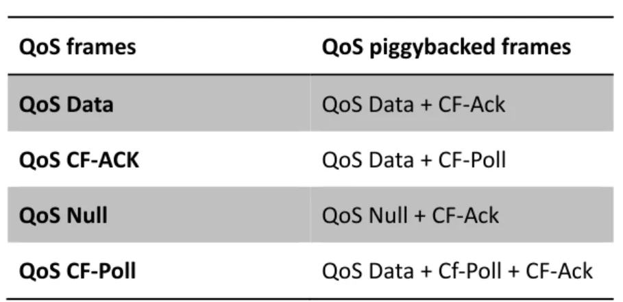
able to process the additional frames which are reported in Table 2.2. Table 2.2: QoS frames. QoS frames QoS piggybacked frames QoS Data QoS Data + CF‐Ack QoS CF‐ACK QoS Data + CF‐Poll QoS Null QoS Null + CF‐Ack QoS CF‐Poll QoS Data + Cf‐Poll + CF‐Ack
Figure 2.10 shows an example of IEEE 802.11e beacon interval used in HCCA. During a beacon interval, a QAP is allowed to start several contention-free bursts called Controlled Access Phases (CAPs). A CAP is a time interval during which the QAP may either transmit MSDUs of established downlink traffic streams or poll one or more QSTAs by specifying the maximum duration of the transmission opportunity (TXOP). A QSTA is never allowed to exceed the TXOP limit imposed by the QAP, including inter-frame spaces and acknowledgments. If a polled QSTA has no data to send, then the QSTA responds with a QoS-Null frame.
Figure 2.10: An example of 802.11e beacon interval used in HCCA.
Upon receiving a TSPEC, the HC invokes it scheduler in order to perform admission control and scheduling. The admission control function is used to determine whether resources are available to serve the requested TSPEC; and the scheduling function is used to determine the manner the HC will poll traffic streams so as to satisfy their QoS requirements. As a result of this operation, the HC may decide to accept, reject or propose an alternative TSPEC to the requesting QSTA.
In IEEE 802.11e sample HCCA scheduler [1], the schedule for an admitted stream is calculated in two steps. The first step is to calculate the scheduled SI. In the second step, the HC would calculate the TXOP duration with scheduled SI for the streams.
The calculation of the scheduled service interval is done in two steps. First, the scheduler calculates the minimum, SImin, of all maximum SIs (MSI) for all admitted traffic streams.
Second, the scheduler chooses a value that is a sub-multiple of beacon interval and is smaller than SImin. This value is the scheduled SI for all admitted TSs.
The next procedure is the calculation of the TXOP duration for an admitted traffic stream. First, the HC calculates the number of MSDUs that arrived with the mean data rate during the SI by ρi i i SI N L ⎡ × ⎤ = ⎢ ⎥
⎢ ⎥, where ρi is the mean data arrival rate for streams i and Li is the nominal MSDU size of stream i. Then the HC calculates the TXOP duration as the maximum of time to transmit Ni frame with rate Ri and time to transmit one maximum size MSDU with
transmission rate Ri by i max i i ,
i i N L M TXOP O O R R ⎛ × ⎞ = ⎜ + + ⎟
⎝ ⎠ , where O is the overhead of transmission.
When a new traffic stream requests registration, the admission control process can be done in three steps. The HC needs to use above two formulas to calculate the values of Ni and
TXOPi after first two steps. Finally, the HC determines whether the stream can be admitted
1 n cp new i i T T TXOP TXOP SI = SI BI − +
∑
≤ , (3) Where TXOPnew is the calculated TXOP duration of the new stream and the second term, isthe sum of TXOP durations of existed streams, BI indicates the beacon interval and Tcp is the
time used for EDCA traffic. Moreover, the HC needs to ensure that it doesn’t allocate TXOP durations that exceed dot11CAPlimit. This algorithm ensures that a new incoming traffic stream doesn’t occupy all the remaining time period.
2.3 Comparison between WLAN MACs
In the previous sections, we know that there are two types of MAC access functions in WLAN. One is contention-based, such as DCF and EDCA; the other is poll-based which includes PCF and HCCA.
The advantage of contention-based access functions is that they are adaptive to the migration in the network condition and are suitable for high load of traffic. Another advantage is the simplicity in implementation. The complexity of contention-based access function is lower than the poll-based access functions due to its distributed access characteristics. However, this kind of access function has some disadvantages. For example, when multiple transmissions contend for the same channel, the problems of collision and hidden-node may be encountered. The random back-off mechanism is another problem for provisioning QoS, it can’t guarantee QoS for real-time traffic.
On the other hand, there are several advantages in using poll-based mechanism; one is eliminating the hidden-node problem; another one is QoS guarantee, this is due to the characteristics of contention-free and centralized-based mechanism. Here the channel utilization is much better than that of contention-based functions because of the reduction of back-off time overhead and collision problem. However, the implementation complexity of
poll-based functions is higher than contention-based functions. And the poll-based functions need to be implemented in the infrastructure wireless networks. The overhead of polling is also an issue in using poll-based access functions.
2.4 Multimedia traffic attributes
In this section, we will introduce the QoS traffic attributes such as number of frames per second (fps), frame duration and required bandwidth.
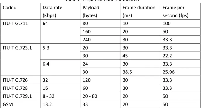
In implementation, VoIP traffic generally can be classified into two types. One is the variable bit rate (VBR), with which the codec generates VoIP packets while in talking; the other is constant bit rate (CBR), with which the codec generates VoIP packets whether the user is talking or not. CBR codec generates VoIP packets in the fixed interval. In the Table 2.3, we can see that VoIP packets feature some characteristics: high transmission interval and small payload size. Also an interesting point is that the different VoIP codec may use the different transmission frequencies.
Table 2.3: Speech Codec standards Codec Data rate (Kbps) Payload (bytes) Frame duration (ms) Frame per second (fps) ITU‐T G.711 64 80 10 100 160 20 50 240 30 33.3 ITU‐T G.723.1 5.3 20 30 33.3 30 45 22.2 6.4 24 30 33.3 30 38.5 25.96 ITU‐T G.726 32 120 30 33.3 ITU‐T G.728 16 60 30 33.3 ITU‐T G.729.1 8 ‐ 32 20 ‐ 80 20 50 GSM 13.2 33 20 50
In a common video data flow, the frame generation of codec is 30 fps (frame per second) with NTSC format. It means that the receivers need to handle more than 30 packets from video source per second. Generally speaking, the sensitivity of delay for a video is lower than that for a voice, therefore the priority of transmission for the video is lower than the voice. Some of video applications are Constant Bit Rate (CBR), but for the sake of video quality, some video applications use Variable Bit Rate (VBR).
2.5 Related Works
According our survey, most of existing EDCA enhanced schemes, such as CWmin, TXOP duration, persistence factor, and AIFSN were trying to adjust the parameters of EDCA. In [22] and [23], authors are trying to tune the CWmin. In [22], it offered an Adaptive EDCF scheme. The QAP tunes the CW sizes for different classes after receiving the average collision rate measures from different QSTAs. The study in [23] recommends using different values of CWmin and CWmax for different priorities, in which higher priority has lower CWmin and CWmax values than those in lower priorities. Some adaptive schemes were proposed to change the persistence factor (PF), the study in [24] proposes a method based on the back-off increase function. In the original DCF, the CW is multiplied by a PF of 2 after each collision. The method in this work is that the higher priority traffic has a lower PF. In
[25], it suggests a way that adapts CW according to channel conditions and adjusts its value depending on the network utilization rather than generating a new random CW.
About HCCA, the reference scheduler of 802.11 task group assumes that all types of traffic are constant bit rate (CBR), so the queue length increases linearly according to the constant application data rate. However, many real-time applications, such as video, are variable bit rate (VBR) traffic. Hence, the basic HCCA scheduler is not suitable for VBR
traffic. Some improvements are offered in works [8] and [15]. Fair Hybrid Coordination Function (FHCF) [8] scheme tries to address VBR traffic by adjusting the TXOP of each flow using queue length estimations. In [15], it offers a bound-based earliest due date (SETT-EDD) scheduling algorithm and uses the additional information from applications. The SET-EDD scheduler also takes into account the impact of link adaptation. Regarding the survey of polling scheme, we found some polling methods are trying to find a mechanism in HCCA to avoid unnecessary polling in order to reduce the polling overhead [7]. Some works [3] [5]
were trying to change the polling order for the VoIP traffic according to the state of traffic streams.
Chapter 3
Proposed Scheme
In the previous chapter, we know that the DCF and EDCA are neither effective nor efficient to support delay-sensitive voice traffic. It is because their contention-based nature and binary exponential back-off mechanism can’t guarantee the delay bound of multimedia packet transmissions. For this reason, in order to guarantee the delay requirement of time-sensitive services, the HCCA function is preferred for real-time applications in WLAN, in which the AP polls each voice source periodically. The IEEE802.11e standard proposes a reference HCCA scheduler that is efficient for the traffic flows with strict CBR characteristics. However, lots of applications such as VoIP, and video which have VBR characteristics and the reference scheduler could not adapt to this kind of traffic.
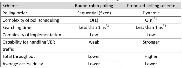
In this chapter, we propose a highly efficient polling (HEP) scheme based on HCCA to provide better QoS in wireless LAN. This proposed scheme is used to eliminate the problem of polling overhead, access latency, jitter and utilization of channel. The HEP scheme operates on the MAC layer in the AP to manage the polling schedule. Table 3.1 shows the comparison of our proposed polling scheme with round-robin polling scheme.
Table 3.1: The comparisons of polling schemes.
Scheme Round‐robin polling Proposed polling scheme Polling order Sequential (fixed) Dynamic
Complexity of poll scheduling O(1) O(n)*1 Searching time Less than 1 µs*2 Less than 1 µs*2 Complexity of implementation Low Low Capability for handling VBR
traffic
weak Stronger Total throughput Lower Higher Average access delay Lower Lower
*1: n is the number of traffic stream *2: based on n < 100
The HEP scheme is fully compatible with current 802.11e MAC, that is, it works on both HCCA and EDCA modes. Further, the HEP scheme takes not only the real-time but also the non-real-time traffic streams into consideration. HEP will put the time-sensitive streams into HCCA mode and put other non-real-time streams into EDCA mode. Hence, the guarantee of QoS for real-time streams can be realized.
Besides the EDCA mode, HEP can also support bi-directional communications in HCCA mode. When the polled stream is determined, the HC would check the queue of download stream. If download queue of real-time stream is available, HC will send QoS data with CF-Poll to the corresponding QSTA; otherwise, the HC will only send a QoS CF-Poll to QSTA. Moreover, the HC could also send data to the QSTAs after the polling procedure as long as the CAP is not over.
3.1 Main Architecture
The proposed HEP scheme maintains a polling list for keeping the information of traffic streams. The elements of polling list will be introduced in Section 3.2.1. HEP consists of three parts, Polling Order Selector (POS) module, Estimated Time Management (ETM) module, and Silence Handler (SH) module.
The POS module is responsible for choosing the suitable entry from the polling list, and to determine TXOP duration for traffic stream. When CFP or CAP starts, the POS module needs to query the next polling station information from the polling list, and send its decision to the frame sending module to poll the selected QSTA.
the MAC identifies the frame type as data, it needs to decode the extended QoS control field, and send an event message to ETM module. The ETM module will adjust the estimated polling time of traffic stream according to the value specified in the extended QoS control field of the data frame.
Moreover, if the HC’s MAC receives a QoS-Null frame from stations, it shall send an event message to inform the SH module. The SH module is responsible for identifying the status of stations. If SH module continues to receive the QoS-Null events and no data frame is received after a specified number of CAPs, it will consider the station as in silence state. Then, SH module will update the estimated polling time in the polling list to a larger interval.
Figure 3.1 shows the architecture of our proposed scheme on HC. Frames arriving at MAC are classified first in order to be served by EDCA or HCCA, if a frame was classified to be served by HCCA, it should be en-queued into the appropriate transmission queue.
3.2 Structure of Polling List
In order to implement our highly efficient polling scheme, we defined a new data structure for the Polling-List. For efficiency consideration, we establish the Polling List with an array, instead of link-list data structure. Moreover, due to the limited number of client stations, we use the linear search to find the next target to be polled, so that the implementation complexity is greatly reduced. In the following sections, we will explain the necessary elements and the maintenance of the proposed polling list.
3.2.1 The format of Polling List
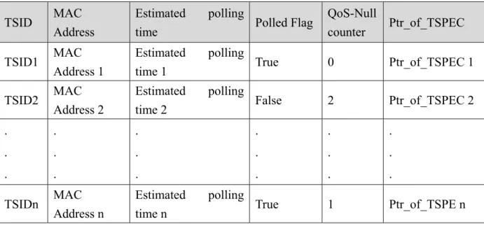
The IEEE 802.11e sample scheduler uses the round-robin strategy as polling scheme, it is only recorded the information of TSPEC for each traffic streams. However, the number of elements it used is not suitable for implementing our scheme. For the reason, we need to define a new structure of polling list (see Table 3.2). After proposed polling list is built, the new polling scheme can use this polling list to determine the polling sequence.
Table 3.2: The format of proposed polling list. TSID MAC
Address
Estimated polling
time Polled Flag
QoS-Null
counter Ptr_of_TSPEC TSID1 MAC
Address 1
Estimated polling
time 1 True 0 Ptr_of_TSPEC 1 TSID2 MAC
Address 2
Estimated polling
time 2 False 2 Ptr_of_TSPEC 2 . . . . . . . . . . . . . . . . . . TSIDn MAC Address n Estimated polling
The elements of proposed polling list are explained in the following section:
TSID (Integer (0..7)): The traffic stream identifier field is used to identify the traffic stream with a particular number. The TSID is assigned by the layer above the MAC. By the way, different QSTAs may use the same TSID. Hence, the TSID and MAC address fields will be combined to specify an unique entry in polling list. (Note: The value of TSID greater than 7 in our design is used for downstream transmissions.)
MAC Address (Octet string (6)): The MAC address of the QSTA.
Estimated polling time (Float): The estimated polling time is calculated by HC for each traffic stream. When a CAP starts, the HC will choose the earliest one to be polled as the candidate traffic stream.
Polled Flag (Boolean): This flag is used to decide whether the traffic stream has been polled or not. We assume that a traffic stream could be polled at most once during a CAP. QoS-Null counter (Integer (0..2)): This counter is used to record the number of QoS-Null frame received from each traffic stream. The new scheme could use this field to determine the status of traffic stream.
Ptr_of_TSPEC (pointer): The field records the pointer linked to TSPEC table of registered traffic streams.
Moreover, the default value of QoS-Null counter element is set to zero, it will be incremented by one every time HC founds that the polled traffic stream replies with a QoS-Null frame. After a successful data frame transmission, the element will be reset to zero. When the value of this element is greater than or equal to two, the HC will consider the traffic stream as in silence state and extend the polling interval for the traffic stream.
3.2.2 The maintenance of Polling List
There are four actions for the polling list: Add a new entry:
If a traffic stream is authenticated after the procedure of admission control, the scheduler will create a new entry for authenticated traffic stream.
Delete an existed entry:
An active traffic stream becomes inactive following a traffic stream deletion process triggered by QSTA or HC. It also becomes inactive following a traffic stream timeout detected by the HC. When an active traffic stream becomes inactive, its information recorded in
polling list will be removed.
Query the next polling traffic stream:
When CFP or CAP starts, the HC needs to query the port list for finding the entry with earliest-due-date first policy. Then, the HC will send the QoS-Poll to the station according to the selected information.
Update the entry:
¾ Upon receiving a QoS-Null frame from the specified traffic stream, the HC should check QoS-Null counter in the poll list. If the counter is larger than the specified value, it will be reset to zero; otherwise, it will be increased by one.
¾ When receiving a QoS Data frame from the specified traffic stream, the HC shall reset the QoS-Null counter in the polling list.
3.3 Polling Mechanism
The polling based scheduler starts to poll a new traffic stream at its service start time which is registered in the accepted TSPEC. The service start time is defined in TSPEC means the first time this traffic stream needs the QoS-Poll from HC for transferring the data frame. To ease the implementation, the original HCCA or PCF function tend to poll all accepted traffic streams in a contention-free period (CFP). So, these two functions may start to poll the stations before their service start time. It will increase the overhead of polling because these traffic streams may not be ready to send data frames. In order to avoid this problem, the HC should start to poll those traffic streams exactly at its specified service start time when new traffic streams are accepted.
In our proposed scheme, when a traffic stream has been polled, the HC estimated the next time to poll this stream by adding the maximum service interval defined in TSPEC specified for this frame. Unlike the reference scheduler, we use adaptive polling interval for each traffic stream. The proposed scheme uses the maximum service interval as estimated service interval instead of minimum service interval in order to avoid the overhead of unnecessary polling. The estimated polling time is calculated as following formulas:
1st estimated-polling-timei = service-start-timei (defined in TSPEC),
2nd estimated-polling-timei = 1st estimated-polling-time + MSIi ,
…
Nth estimated-polling-timei = (N-1)th estimated-polling-timei + MSIi, (4)
,Where estimated-polling-timei means the estimated time at which the traffic stream i will be
polled; MSIi is the maximum service interval specified in TSPEC for the traffic stream i.
scheduler. Before the HC sends the QoS-Poll frames to the registered traffic streams, it needs to detect the state of channel first. If the channel is busy, the HC should wait for the channel to become free; if the channel is detected free, the HC still needs to wait for PCF Inter-frame Space (PIFS); then, if the channel idle has been lasting a PIFS, the HC will get the right to send CF-Poll frame by assigning the TXOPs to the polled traffic stream. All of the HCs and the polled stations will exchange frames with ACK, data, CF-end and so on after an interval of SIFS.
If the polled station finishes its transmission before the assigned TXOP duration expires, it will send a QoS-Null frame to the HC. When the HC got the QoS-Null frame from polled station, it goes to poll the next station immediately. If all the stations had been polled before the end of CAP duration, the HC may transmit downstream packets if any or send the CF-End frame to all stations and back to EDCA mode. The HC may alos poll the QSTAs with piggyback method in the HCCA, such as QoS Data + CF-ACK + CF-Poll, QoS Data + CF-Poll and so on.
Generally speaking, there is a clock residing in intelligent network equipments. In the application of scheduler, this clock is an important component. When the HC assigns a TXOP for the traffic stream, it need to wait for a period same as TXOP duration; and the polled station can transmit its data frame by using assigned TXOP. In the time-stamp based polling, the time synchronization between the HC and the station seems more important. We take the service start time defined in TSPEC as an example, if the clock in the QAP is not synchronized with the station and the clock in station is earlier than the one in the HC, then the HC will be delayed in polling the station. This is because that the actual service start time has been shifted, according to the formula 3.1, all the succeeding estimated service polling time would be shifted, too. For this reason, we suggest that the timer need to be synchronized through some mechanism, such as SNTP or other time protocols. Throughout this thesis, we assume that the time is synchronized between the HC and the stations.
3.3.1 Highly Efficient Polling Scheme
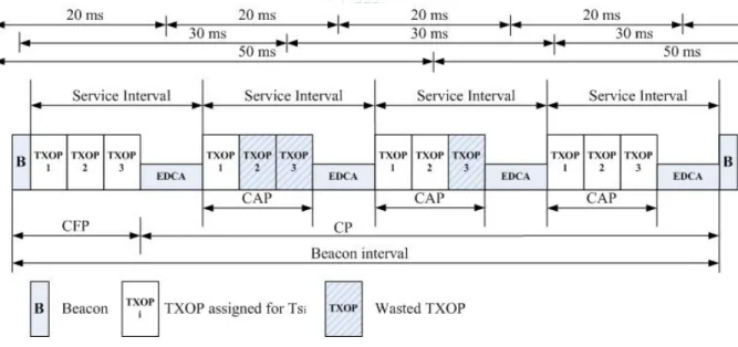
In IEEE 802.11e reference scheduler of HCCA mechanism, the HC chooses the smallest service interval among all maximum service intervals of registered traffic streams as the working service interval. For example, there are three registered traffic streams, traffic stream 1, traffic stream 2, and traffic stream 3 whose maximum service intervals are 20 ms, 30 ms and 50 ms, respectively. Then, the HC will choose the 20 ms as its working service interval. By the way, the HC will start a controlled access phase (CAP) duration after each working service interval.
Figure 3.2: IEEE 802.11e reference RR polling scheme.
Figure 3.2 shows an example using the IEEE 802.11e reference round-robin polling scheme. In this case, there are three traffic streams which need to be polled for transmission based on HCCA function. The traffic stream 1 requests a maximum polling interval of 20 ms that equals to the duration its codec generates the frames. Traffic stream 2 requests a maximum polling interval of 30 ms and traffic stream 3 requests a maximum polling interval
of 50 ms. The beacon interval in this example is 80ms. The HC will choose 20 ms as the working service interval to start contention-free periods (CFPs) or CAPs. After the beacon duration, HC will start the CFP and poll the QSTAs one by one. After all the QSTAs have been polled, it will enter EDCA period till its end. It might be an issue of this mechanism: In 2nd and 3rd service period, the polls QSTA 3 do not make sense; also in 2nd service period, the poll for QSTA2 will be useless. These unnecessary polls will cause extra polling overheads and decrease the utilization of channel. Moreover, the polling order of reference scheduler is fixed, so it may cause a high delay jitter.
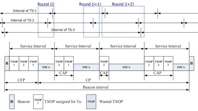
These two problems are resolved in our proposed Highly Efficient Polling (HEP) scheme. Figure 3.3 shows the HEP polling scheme. In this figure, we assume the schedule SI is same as the reference scheduler. When CAP starts, the HC needs to query the polling list for selecting next polling target with earliest-due-time-first strategy. We take round 1 as an example, the estimated polling time of stream-1 and stream-2 matched the polling condition, but the estimated polling interval of stream-3 is not in the round 1. According to our proposed polling scheme, the HC would not poll the stream-3 because it considers this poll as unnecessary polling. Next, the HC would poll the stream-2 because the estimated polling time of stream-2 is earlier than stream-1. In this example, we can notice the problems of polling overhead and delay-jitter could be improved by our scheme.
Figure 3.3: The HEP polling scheme.
3.3.2 Dynamic adjustment of estimated polling time
For reducing the latency of polling, we need to precisely estimate the time that media codec generates a frame. If we use the traffic stream registered time as the start time of the traffic stream, it may cause a large difference between the estimated polling time and actual queueing time (see Figure 3.4). For solving this problem, we propose an optional mechanism, which could be implemented on both QAP and QSTAs.
Figure 3.4: An issue of start time of estimated polling.
In IEEE 802.11e standard, it adds a so-called “QoS control field” for the transmission of QoS related information. In our scheme, we would make use of the reserved parts in QoS
control field for transmitting information HEP needs.
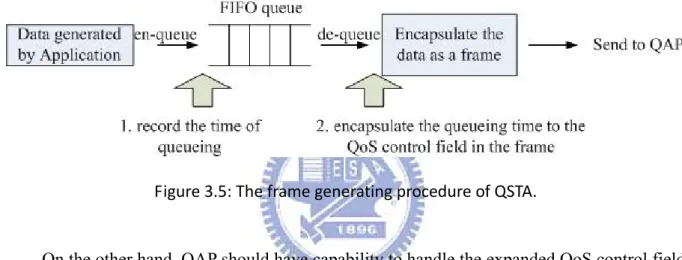
On the one hand, the QSTA needs to do an expansion in FIFO queue. When codec sends a data to FIFO queue for transmission, it needs to record the time of data arrival, which can be considered as equivalent to the data generation time. After the QSTA got the CF-Poll frame from HC, the MAC layer handler of QSTA encapsulates the value of queueing time into the QoS control field of the sending frame. The queueing time is equal to dequeue time minus enqueue time. The modified procedure of a QSTA is shown in Figure 3.5.
Figure 3.5: The frame generating procedure of QSTA.
On the other hand, QAP should have capability to handle the expanded QoS control field of frames from QSTAs. When the QAP receives the data frame from the QSTAs, it fetches the time information from frame and updates the estimated polling time to its Polling List.
Through this mechanism, HC could more precisely estimates the appropriate polling time of traffic stream. Moreover, HC can dynamically adjust the estimated polling time after receiving a frame from QSTAs. For this reason, the difference between actual en-queue time and estimated en-queue time can be shortened, and the delay latency can be reduced.
3.4 Silence Detection Handling
suppression technique to reduce bandwidth consumption. We consider the alternation of talk-spurt and silence of voice traffic streams, and the HC only tries to poll those QSTAs in the talk-spurt state. There are two key points to be considered in using silence suppression technique. The first one is how to determine the state of QSTA; the other one is to detect the time that a silent traffic stream comes back to talk state.
Generally speaking, it is not easy for HC to know the exact starting time and end of talking time. For this reason, the reference scheduler ignores the characteristics of voice, it still polls those voice traffic streams even in the silence state. This kind of scheduler might be simple to implement but it causes the waste of bandwidth. Polling those silent traffic streams might cause two problems: low channel utilization and large access delay. The former problem occurs due to the polling overhead when HC sends an unnecessary poll and the silent station replies with a QoS-Null frame; the latter problem is that talk-spurt traffic streams might be delayed for the unnecessary polls of silent traffic streams.
For reducing the waste of bandwidth, we propose a simple mechanism to determine whether traffic stream is in talk-spurt state or silence state. Then, the estimated polling interval will be different due to the difference of traffic stream states. Our method is based on the replies of CF-Poll frames. During CAP period, the HC sends CF-Poll frames to traffic streams. If the polled traffic stream replied with QoS data frames, the HC will consider this traffic stream as in talk-spurt state. On the other hand, if the polled traffic stream replies with QoS-Null frames for a consecutive number of times, the HC will consider the traffic stream as in silence state. The detection scheme is shown in Figure 3.6. Further, we think that it will be another issue in choosing a specific number for probing. If we set the probe number to a small value, the traffic streams have more chances be detected as in silence state, then the channel utilization may be greatly improved. However, the HC also have higher probability to do a wrong decision in this case. As a result of wrong decision, the talking traffic streams can’t get the QoS-Poll frames from HC, so they can’t send the data buffed in queues, and the access
delay will be increased. On the other hand, if we set it to a large value, HC may have more chance to do a correct decision, but the bandwidth utilization of this scheme may also be degraded as round-robin polling scheme. Hence, we think that it is a trade-off in choosing this number, so we reserve this number as a configured setting for administration. The default value of this number is two.
Figure 3.6: Proposed talk‐spurt and silence detection method.
With the method of talk-spurt and silence detection, the HC can determine the status of traffic streams. Then, the HC sets different polling intervals for the traffic streams in different states. If a traffic stream is in the talk-spurt state (no matter the Null-count is zero, one, two and so on), the polling interval is set the same as its original requested polling interval. When a traffic stream is detected as in silence state, the polling interval will be increased but no more than 300 ms, this is because if the delay time is higher than 300 ms, it is intolerable in the voice communication quality to users. The value is configurable in our proposed scheme, and the default setting is 100ms. Figure 3.7 shows the effect in using proposed silence handler.
Through assigning a large polling interval for silent traffic streams, we can reduce the polling overhead when the silent traffic streams has been lasting a long period. However, the setting of delay time might become an important subject in our scheme. If the delay time is set to a small value, it can do little even no improvement in channel utilization. If it is set to a larger value, such as 300ms, we may encounter a problem of large access delay. This problem is occurred when the HC determines that the traffic stream changes to silence state and sets the delay time to a large value. Unfortunately, this “silent” traffic stream generates new data frames after a short time. In the worse case, the traffic stream needs to wait for a much larger period to get the QoS-Poll from HC. The access delay will become very large in this case.
For solving the above issue, we proposed a “fast-recover” method in our scheme. This method is based on that the silence traffic stream can transmit frames in the EDCA mode. Similar to section 3.3.2, the HC can discover that the “silent” traffic stream is back to talk-spurt state through the QoS control information in the frame. HC can use the TSID and source MAC address in the MAC header of a frame to identify a traffic stream. Even the traffic streams may spend an unexpected time to contend for the medium because of EDCA function, but this wasted time is still smaller than the delay time setting. Through this “fast-recover” method, the traffic streams in silence state have another way for coming back to talk-spurt state. Figure 3.7 shows the effect in using proposed silence handler with fast-recover method.
Moreover, we propose an other silence/talk detection method in our scheme. This method is based on behavior of speech – in most conversations, uplink and downlink are unlikely both talking. According to this method, HC needs to check the download queue before sending a frame. If the download queue for the polled stream is not empty, HC will send a QoS Data + CF-Poll frame to the QSTA and wait replies from the polled QSTA. If polled QSTA replies with a Data + ACK frame, HC will view the traffic stream as in talking state; otherwise, if HC just received an ACK frame from polled QSTA, it will consider the traffic stream as in silent state. When download streams of this silent traffic stream is paused, HC will consider this traffic stream as back to talk state.
Finally, we do a modification in admission control unit for voice streams. Usually, the voice streams are bi-directional, so the calculation of number of MSDUs that arrived during the SI in sample scheduler may be not suitable. For this reason, we double the number of MSDUs for voice streams in original formula.
Chapter 4
Simulation and Numerical Results
4.1 Simulation Model
In the simulation, we use the NS-2 simulator (version 2.29) [26] with 802.11e supported [27] as platform. The simulation environment is composed of a QAP and variable number of QSTAs (see Figure 4.1).
Figure 4.1: The simulation topology.
The physical and MAC layer parameters are shown in the Table 4.1. The length of a beacon interval is set to 1 second. We use three kind of codec for VoIP: 72 bytes payload with 20ms packet interval, 72 bytes payload with 30ms packet interval, and 72 bytes payload with 50ms packet interval. We use three types of frequency to simulate Video traffic: 10 frame per second (fps), 15 fps, and 30fps. The payload length of each video stream is set to 1000 bytes. Each station generates variable-bit-rate (VBR) traffic according to the two-state talk-silence speech model [18], so we set the talk-spurts period to 7.24 sec and set the silence period with 5.69 second. All video are set as VBR. For best effort test, we use FTP transmissions with 1000 bytes payload length.
Table 4.1: Simulation parameters. Parameters Value Video transmission frequency 10fps/15fps/30fps Voice coding rate in bps 28.8 K/19.2 K/11.52 K Transmission rate in bits/sec 54 M Basic rate in bits/sec 6 M SIFS 16μs PIFS 25μs DIFS 34μs CWmin 31 CWmax 1023
In our simulation, we compared our scheme with round robin polling scheme in the 802.11e reference scheduler.
4.2 Numerical Results
We compared our proposed scheme with round-robin polling based scheduler in access delay, total throughput, and delay jitter for various numbers of stations. The simulation results are presented in the following sections.
4.2.1 Throughput
From Figure 4.2, we can see the decrement of average total throughput as the number of QSTAs increases. The figure shows that the Highly Efficient Polling scheme performs much better than the round-robin polling scheme in total throughput. HEP scheme starts at 19610 K-Bytes and RRP scheme from 18559 K-Bytes when the numbers of CBR and VBR streams are both three, and there are 16 FTP streams. When the number of QoS stations increases, the gap is getting larger between these two polling schemes.
Figure 4.2: The relationship of total throughput and network load.
Table 4.2 shows the average throughput of FTP, VBR and CBR traffic streams in using round robin polling scheme and our proposed polling scheme. In this table, we can find that the throughput in VBR and CBR traffic streams are the same. Hence, we can say that both our proposed polling scheme and RR polling scheme guarantee the transmissions for real-time streams. In Table 4.2, we can also notice that under the same number of traffic streams, our proposed polling scheme has better performance than RR polling scheme in total throughput. From Figure 4.1 with Table 4.2, as the number of traffic streams increases, our proposed polling scheme has more chance to accomplish FTP (best effort) data transmission than RR polling scheme.
Table 4.2: Average throughput between two polling schemes
Number of TSs
Average Throughput (K‐Bytes/sec)
HEP_FTP RR_FTP HEP_VBR RR_VBR HEP_CBR RR_CBR
6 1039.36 980.95 2.00 2.00 48.56 48.56 12 921.38 806.92 5.58 5.58 96.78 96.83 18 807.16 639.25 8.14 8.14 145.22 145.28 24 685.36 462.57 12.82 12.81 192.67 192.67 30 576.68 307.44 15.56 15.56 240.22 240.22 36 469.04 165.53 18.40 18.40 288.56 288.67 Figure 4.3 shows the throughput of best effort traffic against network sizes. It shows a significantly increased gap between HEP with and without silence detection function in one side and RR polling scheme on the other side. The higher throughput in both two HEP schemes is primarily due to the reduction of polling overheads. With silence detection function, the more silence QSTA been detected, the more polling overhead will be reduced.
4.2.2 Access Delay
Figure 4.3 shows the average access delay against different network size for CBR /VBR traffic streams and HE/RR polling schemes. By this figure, the HEP scheme features lower access delay comparing with RR polling scheme due to the reduction of polling overhead. In RR polling scheme, the access delay would be increased with the increase of network size; however, in HEP scheme, and with the increase of network size, the access delay would be decreased. This is because that the more QSTAs need to poll, the CAP duration will be larger, and QSTAs will have more chance to be polled in current CAP.
Figure 4.4: Average access delay of time sensitive traffic against number of QSTA
4.2.3 Delay jitter
In our analysis, the jitter is calculated by using the following equation [29]:
(
receive time j_ ( ) send_time j( )) (
receive time i_ ( ) send_time i( ))
jitter j i − − − = − , where j > i (5)
Figure 4.5 and Figure 4.6 show the delay jitter of one real-time traffic stream in RR polling scheme and our proposed scheme, respectively. They are measured in the network condition with 18 CBR, 18 VBR, and 46 FTP traffic streams. In these two figures, we can see the delay jitter in RR polling scheme (standard deviation S is 10.30) is larger than that in our proposed scheme (standard deviation S is 6.92). In some condition, RRP scheme is even higher than 30 ms (see Figure 4.5).
Figure 4.5: Delay jitter between packets in RR polling scheme.
Figure 4.6: Delay jitter between packets in our proposed scheme.
Chapter 5
Conclusion and Future Work
5.1 Conclusion
In the thesis, we proposed a new polling scheme, called Highly Efficient Polling (HEP) for improving the performance of real-time multimedia traffic over WLAN.
There are several features in our proposed scheme: First, this polling scheme is based on the interval in the estimated polling time of each traffic stream, for the reason, our strategy is to poll the station with earliest-due-time-first instead of round-robin polling of reference scheduler. It can reduce the waste of bandwidth when the polled stations have no data frame to send. Second, in order to precisely detect the actual en-queue time for traffic streams, our scheme uses the QoS control field defined in IEEE 802.11e standard to carry the data arrival information. In this mechanism, QSTAs should encapsulate the actual queueing time to the QoS control field of data frame, HC could use these collected information to adjust the estimated polling time in its Polling List. Third, the proposed scheme could dynamically adjust the service interval of voice transmission according to the characteristics of voice flow. This silence detection function detects the silence streams by counting the QoS-Null frames. When it determines that a traffic stream is in silence state, it will switch to a longer polling interval as estimated polling time for reducing the overhead of polls.
One of the main features in our scheme is the low complexity of implementation. Due to limited number of client stations, we use the liner search to find the next target to be polled, so that the implementation complexity is greatly reduced.
We use NS-2 (ns-allinone-2.29) with ns2 IEEE 802.11 support which contains 802.11e EDCA and HCCA modules to evaluate our highly efficiently polling scheme and round-robin
polling scheme. HEP has shown much better performance than the results using round-robin polling scheme, in term of throughput, access delay and jitter variation.
5.2 Future Work
In the future, we will try to do more comparisons with other polling schemes, as well as do some tests for verifying the decisions of our silence detection mechanism to reduce the polling overhead due to null responses.
![Table 1.1: The IEEE 802.11 family [28]](https://thumb-ap.123doks.com/thumbv2/9libinfo/8019288.160753/11.892.121.818.116.1149/table-the-ieee-family.webp)
![Figure 2.9: The sequence of messages occurring at a traffic stream setup [1].](https://thumb-ap.123doks.com/thumbv2/9libinfo/8019288.160753/22.892.194.740.355.726/figure-the-sequence-messages-occurring-traffic-stream-setup.webp)