This article was downloaded by: [National Chiao Tung University 國立交通 大學]
On: 27 April 2014, At: 23:03 Publisher: Taylor & Francis
Informa Ltd Registered in England and Wales Registered Number: 1072954 Registered office: Mortimer House, 37-41 Mortimer Street, London W1T 3JH, UK
Numerical Heat Transfer,
Part A: Applications: An
International Journal
of Computation and
Methodology
Publication details, including instructions for authors and subscription information: http://www.tandfonline.com/loi/unht20
ANALYSIS OF THE FLOW
IN THE GROOVES OF A
MOLECULAR PUMP
Yeng-Yung Tsui, Chia-Ping Kung, Hong-Ping Cheng Published online: 29 Oct 2010.
To cite this article: Yeng-Yung Tsui, Chia-Ping Kung, Hong-Ping Cheng (2001)
ANALYSIS OF THE FLOW IN THE GROOVES OF A MOLECULAR PUMP, Numerical Heat Transfer, Part A: Applications: An International Journal of Computation and Methodology, 40:1, 73-88, DOI: 10.1080/10407780121549
To link to this article: http://dx.doi.org/10.1080/10407780121549
PLEASE SCROLL DOWN FOR ARTICLE
Taylor & Francis makes every effort to ensure the accuracy of all the information (the “Content”) contained in the publications on our platform. However, Taylor & Francis, our agents, and our licensors make no representations or warranties whatsoever as to the accuracy, completeness, or suitability for any purpose of the Content. Any opinions and views expressed in this publication are the opinions and views of the authors, and are not the views of or endorsed by Taylor & Francis. The accuracy of the Content should not be relied upon and should be independently verified with primary sources of information. Taylor and Francis shall not be liable for any losses, actions, claims, proceedings,
or howsoever caused arising directly or indirectly in connection with, in relation to or arising out of the use of the Content.
This article may be used for research, teaching, and private study purposes. Any substantial or systematic reproduction, redistribution, reselling, loan, sub-licensing, systematic supply, or distribution in any form to anyone is expressly forbidden. Terms & Conditions of access and use can be found at http://www.tandfonline.com/page/terms-and-conditions
ANALYSIS OF THE FLOW IN THE GROOVES OF A
M OLECULAR PUM P
Y eng-Yung Tsui and Chia-Ping Kung
Department of Mechanical Engineering, National Chiao Tung University, Hsinchu 300, Taiwan, Republic of China
Hong-Ping Cheng
Precision Instrument Development Center, Hsinchu 300, Taiwan, Republic of China
A computational procedure used to solve conservation equations governing the slip ow in a molecular pump of the Holweck type is developed . The nite volume method is used for discretization and the grid is arranged in the curvilinear, nonstaggered form. The slip boundary condition is imposed on the solid walls. The clearance gap between the rotor and the casing is ignored. It is evident from the calculation that the pressure difference between the two side walls of the channel, termed pressure side and suction side, varies in accordance with the pressure difference between the inlet and the outlet of the pump. Thus, the side-wall pressure difference can play the role of an indicator of pumping effectiveness. Tests on a variety of con gurations show that to achieve the best perform-ance both the spiral angle and the channel height need to be optimized. Besides, it is better to have fewer ow channels and to place these channels on the rotor instead of on the casing.
INTRODUCTION
The development of the molecular pump dates back to the early 1900s. The ¢rst pump of this type was introduced by Gaede [1] using a series of parallel grooves around the circumference of a rotor. Later, spiral grooves were mounted either on a rotating cylinder by Holweck [2] or on a rotating disc by Siegbahn [3]. These three types of pump are termed the molecular drag pump (MDP). A different design, called the turbomolecular pump (TMP) came from Becker [4], in which the pumping channels are formed by rows of rotating and stationary blades. The MDPs did not draw much attention until recently because of their relatively low pumping speed and questionable reliability during the early days. The TMP has the advantage of high pumping speed and low ultimate pressure. However, the MDP has a high compression ratio and is capable of raising the foreline pressure to the range of
Numerical Heat Transfer, Part A, 40:73^88 , 2001 Copyright # 2001 Taylor & Francis
1040-7782 /01 $12.00 + .00
73 Received 8 January 2001; accepted 24 February 2001.
The authors acknowledge the support provided by the Precision Instrument Development Center of the National Science Council, Republic of China.
Address correspondence to Dr. Y. Y. Tsui, Department of Mechanical Engineering, National Chiao Tung University, 1001 Ta Hsueh Road, Hsinchu, Taiwan 30050, Republic of China.
1 to 103 pa. Therefore, through combination of the TMPs with the MDPs the
demanding of high throughputs together with high discharge pressures can be achieved.
The pumping principle of the molecular pumps is based on the occurrence of when gas molecules impinge on a rapidly rotating surface, momentum is imparted to the gas to counterbalance the pressure rise encountered in the £ow channel. One way to model the molecular £ow in these pumps makes use of the equation given by Gaede in [5^7]. Another approach developed by Kruger and Shapiro [8] uses the Monte Carlo method to calculate the probabilities of molecules passing through the £ow channels from both the inlet and the outlet. With these transmission probabilities the maximum compression ratio and pumping speed can be obtained. The above approaches are applicable to the free molecular £ow. For the £ow in the transition regime the direct simulation Monte Carlo method is the most suitable [9, 10]. As mentioned before, the working pressure for the MDP can be up to 103 pa.
At these high operation pressures the £ow in the pump will reach the continuum regime. Not much effort was devoted to this area in the past. In some research the analysis is based on the superposition of a Poiseuille £ow on a Couette £ow [6, 11]. Apparently, this simple analytic model cannot fully re£ect the real £ow in the pump. In this study the full Navier^Stokes equation are solved using a numeri-cal method to investigate the £ow behavior in the Holweck-type pump. The £ow is in the slip £ow regime, and, thus, the slip boundary condition is employed in the calculation.
M ATHEM ATICAL M ETHOD
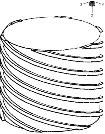
A schematic drawing of the rotor of the Holweck-type molecular pump is illus-trated in Figure 1. There are six grooves on the rotor. Because of the periodic arrangement only one groove is considered in the calculation. Because the Reynolds number is less than 20 in the current study, the £ow is in the laminar regime. The £ow
NOM ENCLATURE A cross-sectional area Bij diffusion matrix f accommodation coef¢cient of momentum h channel height J Jacobian of coordinate transformation Kn Knudsen number p pressure r radial coordinate ~ R position vector T temperature
Ui contravariant velocity in the xi
direction ~
V £ow velocity vector
a channel angle f transport entity l mean free path m dynamic viscosity m0 apparent viscosity
r density
xi curvilinear coordinates
~
O angular velocity vector Subscripts
p value at pressure side s value at suction side w wall value
1 value at inlet 2 value at exit
is assumed to be ¢xed at the room temperature of 300¯K. In the numerical
calculation the conservation equations of mass and momentum together with the equation of state are solved. Because the £ow grooves are sited on the rotor, a rotating frame of reference is necessary. To cope with the helical geometry of the grooves a transformation from the cylindrical coordinates to the curvilinear coordinates is undertaken. Then the governing equations can be written in the following form: 1 Jr @ @xi…rUif†ˆ 1 Jr @ @xi m Jr Bij @f @xj
( )
" # ‡ Sf …1†where f stands for the velocity components in the cylindrical coordinates, and Bij
represents the diffusion matrix. For details of this matrix, see Tsui and colleagues [12]. The rotation of the frame gives rise to centrifugal force and Coriolis force, which are absorbed in the source term Sf.
~
F ˆ ¡2r~O £ ~V ‡ r ~O £…O £ ~R~ † …2†
Figure 1. A schematic drawing of the pump.
FLOW IN THE GROOVES OF A MOLECULAR PUMP 75
From gas kinetics it can be shown that the mean free path of gas molecules l is related to the pressure and temperature as
lP
T ˆconst …3†
The discharge pressure of the pump of the current study is ¢xed at 133 pa ( ˆ 1 torr). According to the above relation, the mean free path is around 0.05 mm. The Knudsen number, Knˆ l=h, where h is the height of the £ow channel ( ˆ 4.06 mm),
is around 0.01. Therefore, the £ow ¢eld will cover the slip £ow regime. The slip £ow at the solid wall is most commonly given as
Voˆ Vw‡2 ¡ ff l
( )
dVdyw …
4†
where Vois the £ow velocity at the wall, Vwis the velocity of the solid wall itself, and f
is the accommodation coef¢cient of momentum. The accommodation coef¢cient usually takes a value close to 1. In the current calculation the value of unity is adopted.
The governing equations shown in Eq. (1) are of divergence form. By applying the Gauss theorem of divergence, we can transform volume integral of the equation to a surface integral. Then the task of discretization can be accomplished via suitable evaluation of the covective and diffusive £uxes. Convection terms are approximated by the second-order linear upwind difference [13], whereas the diffusion terms are approximated by the central difference. The grids used are arranged in the nonstaggered manner; that is all dependent variables are collocated at the cell center. To avoid the pressure-velocity decoupling caused by the nonstaggered grid arrangement, a special interpolation practice [14] is utilized to calculate the mass £ux through each cell face. By forcing the mass £uxes to satisfy the continuity con-straint a pressure-correction equation is obtained. An iterative solution procedure can then be employed.
The implementation of the slip boundary condition deserves a discussion. A drawing of a control volume adjacent to a solid wall is given in Figure 2. The shear stress at the wall can be calculated as
t ˆ m
( )
dVdywˆ m
Vp¡ Vo
dn …5†
where dn is the normal distance form the point p to the wall. The gas velocity at the wall can be approximated as
Voˆ Vw‡2 ¡ ff lVp¡ Vo
dn …6†
A direct way to implement the boundary condition can be obtained via successive substitution of Vo given by the above equation into Eq. (5) during the solution
iteration. However, in this manner the solution procedure is not easy to converge because the velocity Vo on the right-hand side of Eq. (6) lags by one iteration.
A better way is given as follows. Because
Vp¡ Voˆ …Vp¡ Vw†
…1 ‡…2 ¡ f†=f…l=dn†† …7†
the shear stress can be calculated from
t ˆ m0Vp¡ Vw
dn …8†
Here m0 stands for an apparent viscosity:
m0ˆ m
1 ‡…2 ¡ f†=f…l=dn† …9†
RESULTS AND DISCUSSION
In the current study the baseline con¢guration of the pump considered is the same as that used by Nanbu and Igarashi [15]. However, in the calculation of Nanbu and Igarashi’s con¢guration the £ow channel was treated as a rectangular channel and a stationary frame was used. The axial length of the pump is 53.5 mm while the outer diameter of the rotor is 137.6 mm. There are six spiral channels on the rotor. The width and height of each channel are 53.5 mm and 4.06 mm. The spiral angle of the channel is 15¯. The clearance between the casing and the rotor
is ignored. The rotor rotates at 18000 rpm. Nitrogen is used as the working £uid. Figure 2. Illustration of a control volume near the wall.
FLOW IN THE GROOVES OF A MOLECULAR PUMP 77
The pumping process is assumed to be isothermal at 300¯K. The outlet pressure
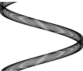
is maintained at a ¢xed level of 133 pa and a number of mass £ow rates, 300 sccm, 600 sccm, 960 sccm, and 1440 sccm, are under consideration. Three different levels of grid, 52*22*12, 102*32*22 , and 132*52*32 have been tested to exam grid sensitivity. A typical grid is illustrated in Figure 3. The differences in the resulting pressure distribution are insigni¢cant. Thus, the second level of mesh is used in the following.
To illustrate £ow structure the contours of the axial velocity and the transverse velocity vectors at x/L ˆ 0.6 and 1 for 300 sccm and 960 sccm are shown in Figures 4 and 5. Here L stands for the total length of the £ow channel. For the low £ow rate reverse £ow forms at the two side walls in the lower half of the channel. The strength of the reverse £ow decreases as the £ow rate increases because the adverse pressure gradient prevailing in the pump is reduced accordingly, which will be clear in the following. Because of the moving wall at the top the transverse £ow behaves like a Couette £ow. However, as seen from Figure 4, the £ow pattern is transformed to a cavity £ow when reverse £ow takes place near the bottom wall at the low £ow rate.
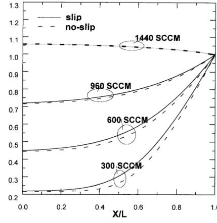
The variation of the pressure, averaged over the transverse plane, is shown in Figure 6. In this ¢gure and the following P1and P2denote the pressures at the inlet
and the outlet, respectively. It is seen that the pressure rise across the pump increases as the £ow rate decreases. For the £ow rate of 1440 sccm the pressure decreases monotonically. This indicates that the molecular pump is effective at low pressures. Two sets of results are presented in the ¢gure: one for the use of the slip boundary condition and the other for that of the no-slip boundary condition. For the low £ow rate cases the pressure rise is higher for the no-slip £ow. The cause of this result is ascribed to more momentum being exerted from the moving surface to the gas as the no-slip boundary condition is being applied.
Figure 3. A typical grid arrangement.
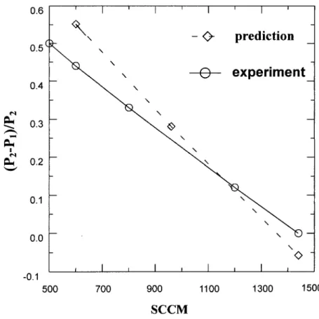
A comparison of the current predictions with the experimental data [15] is given in Figure 7. Both results indicate a linear decrease of the pressure rise with the £ow rate. However, the pressure rise is overpredicted for the low £ow rates. This is believed to be the case because the clearance gap between the rotor and the pump casing is not accounted for in the calculation. To illustrate this point Figure 8 is presented. This ¢gure shows the pressure distribution in a plane at the midheight of the channel. Evidently, there exists a pressure difference between the two side walls. As will be seen in the analysis given below, the pressure rise across the channel is re£ected by this side-wall pressure difference. Because the clearance gap connects the two side walls of the channel, it is expected that the side-wall press-ure difference should decrease and the pumping effectiveness deteriorates accordingly.
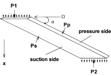
A schematic drawing of the spiral channel is shown in Figure 9, in which the channel is straightened, but with an angle a with respect to the circumferential direction. The side with higher pressure Ppis termed the pressure side and the other
one with Ps is the suction side. The pressure side is located at the upstream side
of the rotation. A force balance over the entire £ow channel in the axial direction Figure 4. Axial velocity contours and secondary velocity vectors at x/L ˆ 0.6 and 1
for 300 sccm. The solid lines represent 5, 10, 15, 20 m/s and the dashed lines ¡1, ¡2 m/s.
FLOW IN THE GROOVES OF A MOLECULAR PUMP 79
is constructed:
…P2¡ P1†A &…Pp¡ Ps†Awcos a ¡ Fx …10†
Here A and Aw designate the cross-sectional area of the channel and the side-wall
area, respectively, and Fx represents the total frictional force exerted by the solid
walls in the axial direction. In the above equation the difference between the inlet and outgoing momentum £uxes is ignored. It is clear from this equation that the pressure difference between the pressure and the suction sides brings about the pressure rise across the channel.
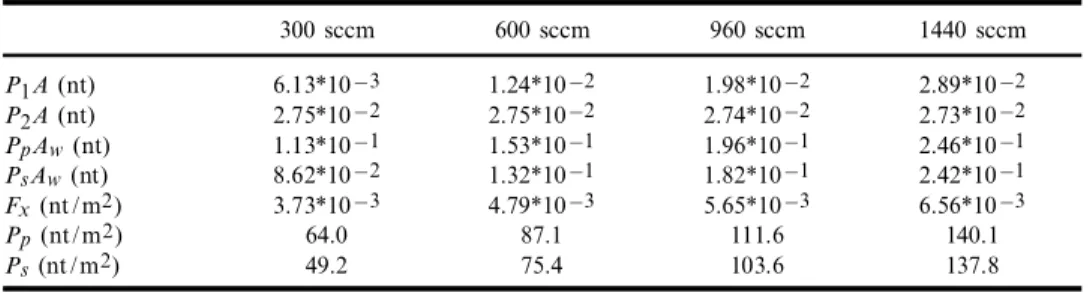
In Table 1 all the terms shown in Eq. (10) together with the average pressures
Pp and Ps are listed. As the £ow rate increases, the pressure difference between
the side walls decreases while the frictional force increases. This results in diminished pressure rise across the pump. Thus, the side-wall pressure difference can be used as an indicator of the effectiveness of the pumping process.
In the following the pump con¢guration is modi¢ed to examine its effects on the pumping performance.
Figure 5. Axial velocity contours and secondary velocity vectors at x/L ˆ 0.6 and 1 for 960 sccm. The solid lines represent 5, 10, 15, 20 m/s and the dashed lines ¡1, ¡2 m/s.
Test of Spiral Angle
The baseline spiral angle a is 15¯. In this test the angle varies from 13¯to 30¯
together with a special case of 90¯. The resulted pressure variation along the £ow
channel for 600 sccm is shown in Figure 10. It is evident that the pressure rise across the channel increases with the spiral angle until a ˆ 25¯, followed by a decrease
thereafter. It can be seen from Table 2 that the side-wall pressure difference increases monotonically with the spiral angle. However, it is noted that this pressure difference is multiplied by cosa in Eq. (10). The value of cosa decreases as the angle increases. Therefore, there exists an optimum value of a. It can also be seen from Figure 10 that the adverse pressure gradient is high in the inlet region for large angles and high in the exit region for small angles. As a consequence, a better design of the channel is to have larger spiral angles at inlet and smaller angles at outlet.
Test of Channel Height
To examine the in£uence of channel height three values of height, 3.5 mm, 4.5 mm, and 6 mm, together with the original height 4.06 mm, are under
consid-Figure 6. Pressure variation along the channel.
FLOW IN THE GROOVES OF A MOLECULAR PUMP 81
eration. It is revealed from Figure 11 for 600 sccm that the pumping performance is enhanced when the channel height is increased up to 4.5 mm, followed by a decrease for the height of 6 mm. The cause of this phenomenon is clear from the following discussion. When the channel height is increased, the cross-sectional area A increases accordingly and the £ow velocity is reduced because the £ow rate remains as a con-stant. Thus, more momentum is transferred from the moving wall to the gas for the large height cases. In addition, less frictional force is caused at the stationary walls in spite of the increase of the side-wall area. This results in better pumping effectiveness. However, it should be understood that with a large channel height the strength of the reverse £ow is stronger, which leads to a greater pressure loss. Examination of the variation of pressure gradient reveals that a better performance can be obtained by having a taper channel: larger height at outlet and smaller height at outlet.
Test of Channel Number
The numbers of £ow channels tested are 4, 6, and 8. Figure 12 reveals that the pumping performance is improved as the channel number decreases. From
Figure 7. Comparison of the pressure rise with measurements.
Table 3 for 600 sccm it is detected that the pressure at the pressure side remains almost constant, but the pressure at the suction side decreases with the channel number. The decrease of channel number brings about wider channel space, which allows a larger pressure difference to form between the side walls by the Couette-like £ow.
Figure 8. Pressure distribution in a plane near the midheight of the channel.
Figure 9. Illustration of the force balance over the entire £ow channel.
FLOW IN THE GROOVES OF A MOLECULAR PUMP 83
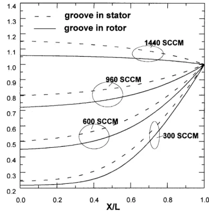
Comparison of the Channels Fixed on the Rotor and the Casing
In the above results the £ow channels are placed on the rotor. Another common practice is to place the channels on the casing. Figure 13 indicates that better per-Table 1. Force balance for various £ow rates
300 sccm 600 sccm 960 sccm 1440 sccm P1A (nt) 6.13*10¡3 1.24*10¡2 1.98*10¡2 2.89*10¡2 P2A (nt) 2.75*10¡2 2.75*10¡2 2.74*10¡2 2.73*10¡2 PpAw(nt) 1.13*10¡1 1.53*10¡1 1.96*10¡1 2.46*10¡1 PsAw(nt) 8.62*10¡2 1.32*10¡1 1.82*10¡1 2.42*10¡1 Fx(nt/m2) 3.73*10¡3 4.79*10¡3 5.65*10¡3 6.56*10¡3 Pp(nt/m2) 64.0 87.1 111.6 140.1 Ps(nt/m2) 49.2 75.4 103.6 137.8
Figure 10. Pressure variation for various spiral angles.
formance is yielded when the channels are ¢xed on the rotor. This is because the speed of the moving wall is higher for this arrangement.
CONCLUSIONS
A three-dimensional numerical analysis model has been successfully developed and applied to examine the £ow in a molecular drag pump of Holweck type. The main ¢ndings are given in the following.
Table 2. Pressures at the pressure side and suction side for various spiral angles
15¯ 25¯ 30¯ 90¯
Pp(nt/m2) 87.1 91.9 97.2 164
Ps(nt/m2) 75.4 68.3 68.5 118.2
Figure 11. Pressure variation for various channel heights.
FLOW IN THE GROOVES OF A MOLECULAR PUMP 85
1. From the analysis it is clear that the pressure rise across the channel can be attributed to the difference between the pressure side and the suction side of the channel.
2. The increase of the spiral angle brings about an increase of the side-wall pressure difference. But the component of this pressure difference in the axial direction decreases with the angle. As a consequence, there exists an optimum value of spiral angle.
Figure 12. Pressure variation for various channel numbers.
Table 3. Pressures at the pressure side and suction side for various channel numbers
4-groove 6-groove 8-groove
Pp(nt/m2) 87.8 87.1 88.6
Ps(nt/m2) 69.9 75.4 80.0
3. The increase of the channel height leads to more momentum being trans-ferred from the moving surface to the gas because the speed of the gas becomes lower. However, it induces stronger reverse £ow. Therefore, the channel height also needs to be optimized. The pressure variation indicates that a better design is to have larger spiral angle and channel height at inlet and smaller spiral angle and height at outlet.
4. When the channel number increases, the spacing between side walls decreases, causing a decrease in the side-pressure difference as well as the pressure rise across the channel.
5. Compared with the placement of the channels on the rotor, the speed of the moving surface is lower as the channels are sited on the casing. It gives rise to lower pumping performance.
REFERENCES
1. W. Gaede, Die Molekularluftpumpe, Annalen der Physik, vol. 41, pp. 337^380 , 1913. 2. F. Holweck, Pompe Moleculaire Helicoidale, C. R. Acad. Sci., vol. 43, p. 177, 1923. 3. M. Siegbahn, A New Design for a High Vacuum Pump, Ark. Math. Astron. Phys.,
vol. 30b, pp. 261^270, 1943.
Figure 13. Pressure variation for the placement of the channel on the rotor and on the casing.
FLOW IN THE GROOVES OF A MOLECULAR PUMP 87
4. W. Becker, Eine Neue Molekularpumpe, Vakuum Technik, vol. 7, p. 49, 1958. 5. W. Becker, The Turbomolecular Pump, Its Design, Operation and Theory: Calculation of
the Pumping Speed for Various Gases and Their Dependence on the Forepump, Vacuum, vol. 16, pp. 625^632, 1966.
6. C. N. Panos, A. G. Antoniou, and S. E. Valamontes, The Helicoid Multi-Groove Vacuum Pump in Both Viscous and Molecular States, Vacuum, vol. 45, pp. 841^847, 1994. 7. A. G. Antoniou, S. E. Valamontes, C. N. Panos, and E. S. Valamontes, The
Turbomolecular Pump in Molecular State, Vacuum, vol. 46, pp. 709^715, 1995. 8. C. H. Kruger and A. H. Shapiro, Vacuum Pumping with a Bladed Axial-Flow
Turbo-Machine, 7th Nat. Symp. Vac. Techn. Transaqct., pp. 6^12, 1960.
9. G. A. Bird, Molecular Gas Dynamics and the Direct Simulation of Gas Flows, Clarendon Press, Oxford, 1994.
10. Y. K. Lee and J. W. Lee, Direct Simulation of Compression Characteristics for a Simple Drag Pump Model, Vacuum, vol. 47, pp. 807^809 , 1996.
11. M. Spanol, R. Cerruti, and J. Helmer, Turbomolecular Pump Design for High Pressure Operation, J. Vac. Sci. Technol., vol. A16, pp. 1151^1156 , 1998.
12. Y.-Y. Tsui, P.-W. Wu, and C.-W. Liao, Flow Modeling in Turbofan Mixing Duct, Numer.
Heat Transfer, Part A, vol. 26, pp. 219^236, 1994.
13. Y. Y. Tsui, A Study of Upstream-Weighted High-Order Differencing for Approximation to Flow Convection, Int. J. Numer. Methods Fluids, vol. 13, pp. 167^199 , 1991. 14. C. M. Rhie and W. L. Chow, A Numerical Study of the Turbulent Flow Past an Isolated
Airfoil with Trailing Edge Separation, AIAA J., vol. 21, pp. 1525^1532 , 1983. 15. K. Nanbu and S. Igarashi, Three-Dimensional Low-Density Flows in the Spiral Grooves
of a Turbo-Molecular Pump, Computers Fluids, vol. 21, pp. 221^228, 1992.