Can: A context-aware NAT traversal scheme
Chien-Chao Tseng
a, Chia-Liang Lin
a,n, Li-Hsing Yen
b, Jyun-Yan Liu
a, Cheng-Yuan Ho
ca
Department of Computer Science, National Chiao Tung University No. 1001 University Road, Hsinchu 300, Taiwan, ROC b
Department of Computer Science and Information Engineering, National University of Kaohsiung No.700, Kaohsiung University Road, Nan Tzu District, Kaohsiung 811, Taiwan, ROC
c
Advanced Research Center, Institute for Information Industry 1F., No.133, Sec. 4, Minsheng E. Road, Songshan District, Taipei City 105, Taiwan, ROC
a r t i c l e
i n f o
Article history: Received 18 July 2012 Received in revised form 10 December 2012 Accepted 1 February 2013 Available online 17 February 2013 Keywords: CAN ICE NAT NAT traversal STUN TURN
a b s t r a c t
Network Address Translation (NAT) is a technique commonly used to share one public IPv4 address among several hosts located behind a NAT device. NAT devices typically block session requests originating from outside, causing NAT traversal problem that prevents the establishment of peer-to-peer (P2P) sessions. There have been many proposals for the NAT traversal problem. However, existing methods induce high connectivity check delay and resource demand when finding a communicating path, calling for a routine that determines the path best suited for a given pair of communicating peers. This study proposes CAN, a Context-Aware NAT traversal scheme which gathers and exchanges network-context information to find the most appropriate path for two communicating peers behind NAT devices. We have implemented CAN and conducted extensive experiments with off-the-shelf NAT devices to compare the performance of CAN with Interactivity Connectivity Establishment (ICE), the most acknowledged approach to creating a session across NATs. Experimental results show that CAN outperforms ICE in terms of direct communication ratio, connectivity check delay and message overload when checking connectivity.
&2013 Elsevier Ltd. All rights reserved.
1. Introduction
Peer-to-peer (P2P) communication has emerged as the main-stream of network applications and has gained immense popu-larity in recent years. P2P communication can not only avoid the expense but also shorten the delay of handling traffic at a server. Voice over internet protocol (VoIP) is one of the most popular P2P applications. However, this style of communication often has problems dealing with Network Address Translation (NAT) (Francis and Egevang, 2001;Stegel et al., 2010;Lin et al., 2010).
NAT is a solution to alleviate the exhaustion of IPv4 address. By modifying network address information stored in packet header when packets pass through a traffic routing device, NAT remaps a given address realm into another, while also providing transparent routing for the hosts behind a NAT. The nature of NAT causes NAT traversal problem (Lin et al., 2010;Aurel Constantinescu et al., 2005;
Ho et al., 2011), which is a barrier to P2P applications. Not until an internal host (IH) behind a NAT device sends a packet to an external host (EH) outside the NAT first can the EH send packets to the IH directly. In other words, NAT device blocks session requests origi-nating from the external side, which prevents the establishment of
P2P sessions. The situation becomes worse when both hosts are behind different NAT devices. As a remedy, many NAT traversal techniques (Yoshimi et al., 2007;Saikat et al., 2004;Rosenberg et al., 2008, 2010; Rosenberg, 2010; Boucadair et al., 2011; Mao et al., 2012; Cuevas et al., 2010; Chen and Jia, 2009; Patro et al., 2011;
Houngue et al., 2011) have been proposed to establish and maintain TCP/IP network sessions across NAT devices. NAT traversal is indispensable for P2P applications running in NAT environment.
Many existing NAT traversal methods rely on a server with publicly routable IP addresses. Some methods only use the server when establishing a session (such as STUN,Rosenberg et al., 2008;
Maenpaa et al., 2010; Bae and Cho, 2010). Some relay all data through the server (such as TURN, Rosenberg et al., 2010;
Houngue et al., 2011;Maenpaa et al., 2010;Bae and Cho, 2010, MOSAIC, Mao et al., 2012, GPA, Cuevas et al., 2010), but these approaches increase both bandwidth costs and latency. These relaying methods are also detrimental to real-time voice and video communication. Some NAT traversal methods do not need a server (such as UPnP,Boucadair et al., 2011;Patro et al., 2011, NATng,Chen and Jia, 2009), but these approaches require mod-ifications on NAT devices. The Internet Engineering Task Force (IETF) proposed Interactive Connectivity Establishment (ICE) (Rosenberg, 2010;Maenpaa et al., 2010)to provide NAT traversal capabilities for session-oriented protocol. ICE makes use of STUN and TURN and provides a unified framework around them. ICE hosts exchange accessibility information and negotiate with each Contents lists available atSciVerse ScienceDirect
journal homepage:www.elsevier.com/locate/jnca
Journal of Network and Computer Applications
1084-8045/$ - see front matter & 2013 Elsevier Ltd. All rights reserved. http://dx.doi.org/10.1016/j.jnca.2013.02.001
n
Corresponding author. Tel.: þ886 3 57121 21x54792; fax: þ 886 3 5721 490. E-mail addresses: [email protected] (C.-C. Tseng),
[email protected] (C.-L. Lin), [email protected] (L.-H. Yen), [email protected] (J.-Y. Liu), [email protected] (C.-Y. Ho).
other to find one or more communication paths between them. However, ICE causes a long connectivity check delay and requires considerable message exchanges because ICE performs a com-plete and systematical connectivity check before selecting a communication path. ICE may also fail to create a direct commu-nication path between two hosts when some host is behind a NAT device that implements connection tracking (Ho et al., 2010;
Raste and Kulkarni, 2008).
As direct communication paths save bandwidth demand and latency caused by relaying methods, direct communication ratio (DCR) serves as another important metric for evaluating a NAT traversal method. Given a set of NAT combinations, DCR is the ratio of combinations for which direct communication paths can be created to all combinations. A traversal method that leads to high DCR naturally demands low relay resource. To improve the DCR and efficiency of ICE, this study proposes Context Aware NAT (CAN) traversal scheme. In CAN, user agents (UAs) of hosts obtain network-context information (host location, NAT type, Saikat et al., 2004; Rosenberg et al., 2003; Audet, 2007; Huang and Hwang, 2009, whether hairpin translation, Ford et al., 2005;
Srisuresh et al., 2008; Kuramochi et al., 2008, is supported and whether connection tracking,Ho et al., 2010;Raste and Kulkarni, 2008, is implemented) in advance. Then both hosts exchange their network-context information to assist in the connectivity check. Since CAN is aware of the network-context, it could eliminate unnecessary checks, shorten check delay and resolve the low-DCR problem caused by connection tracking.
The remainder of this paper is organized as follows. We first describe mapping, filtering behaviors, NAT type, hairpin translation and connection tracking of a NAT device in detail, and then introduce three traversal methods. In the following sections, we will describe the design of CAN, present the setup of experiments and analyze the experiment results. We summarize our findings in the final section.
2. Preliminary
2.1. Background
NAT allows IHs within a private network to connect to EHs in a public network (Francis and Egevang, 2001;Ho et al., 2011,2010). The usage and toleration of NAT ameliorates IPv4 address deple-tion by allowing globally registered IP addresses to be either reused or shared among several hosts. Network Address Port Translation (NAPT) is a commonly adopted NAT implementation, which allows many hosts to share a single IP address through multiplexing streams differentiated by a TCP/UDP port number.
Figure 1 illustrates an example where two hosts with private addresses 192.168.1.1 and 192.168.1.2, respectively, send packets from port number 1234. A NAPT device might translate source addresses of these packets into a single public IP address 140.113.215.215 with two different source ports (for example, 4321 and 4322). In this example, the NAPT device would route response traffic destined for port 4321 to 192.168.1.1:1234, while traffic to port 4322 would go to 192.168.1.2:1234.
In the rest of this paper, NAT refers to NAPT implementation, and a mapped-address is an external global IP address along with a port number allocated by a NAT for a session attempt from an IH. Different NATs may differ in the following behaviors: NAT mapping, packet filtering, implementation of hairpin translation and connection track-ing. These behaviors are discussed in details in the followtrack-ing.
NAT mapping behavior, which refers to how mapped-addresses are allocated to sessions. A mapping chooses an external address and a port for each session. Sessions originating from different IHs are certainly allocated different mapped-addresses. For sessions that originate from the same IH but are destined for different
hosts and/or different ports, mapping policies can be independent mapping, address dependent mapping, or address-and-port dependent mapping (Audet, 2007). Independent mapping NAT uses the same address and port for all outbound packets originat-ing from the same IH regardless of destination address and port (Fig. 2a). Address dependent mapping differentiates sessions that are destined for different EHs. For packets to the same destination address, NAT uses the same mapped-address (Fig. 2b). Finally, address-and-port dependent mapping NAT generates one unique mapped-address for each session (Fig. 2c). Beside these polices, some NATs generate mapped-addresses in a random fashion while some others do so in a sequential order.
Fig. 1. An example of NAPT operation.
Node A Node B Node C Node A Node B Node C Node A Node B Node C NAT NAT NAT
Fig. 2. NAT mapping behavior. (a) Independent; (b) Address Dependent and (c) Address & Port Dependent.
Node A Node B Node C NAT Node A Node B Node C NAT Node A Node B Node C NAT
Fig. 3. NAT filtering behavior. (a) Independent; (b) Address Dependent and (c) Address & Port Dependent.
Packet filtering behavior, which determines whether a packet sent form the external side is allowed to pass through the NAT. The judgment is based on the source address and port number.Audet (2007) classified packet filtering behavior into independent filtering, address dependent filtering, and address-and-port dependent filter-ing. In independent filtering, any EH regardless of its address and port number can send packets to IHs with valid mapped-addresses (Fig. 3a). These mapped-addresses may be created previously for sessions to other EHs. Address dependent filtering only accepts packets sent from an EH for which a mapped-address (Fig. 3b) has been created previously. In address-and-port dependent filtering, packets with source address B and port number b are allowed only if a mapped-address has already been created for that address (B) and port (b) (Fig. 3c).
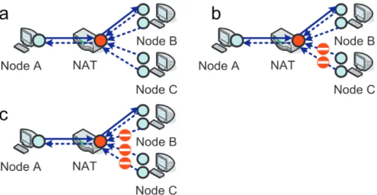
NAT type: Rosenberg et al. (2003) classified port translation method of NAT into cone and symmetric. A cone NAT assigns the same mapped-address for each outgoing session originating from the same transport address of an IH. Cone NATs could further divide into full-cone, address-restricted cone and port-restricted cone. A full cone (FC) NAT has an independent filtering behavior, which allows any EH regardless of its address and port number to send packets to IHs with correct mapped-address. An address-restricted cone (AR) NAT with address dependent filtering behavior only allows packets from the same address IHs ever sent. Port-restricted cone (PR) NAT is similar to AR NAT, except that the restriction includes port numbers. A symmetric (SY) NAT generates a unique mapped-address for each session destined for different transport address and allows incoming packets only if a mapped-address has already been created for that address and port.
Hairpin (Loopback) translation (Ford et al., 2005; Srisuresh et al., 2008;Kuramochi et al., 2008) applies to the case that two hosts (Hosts A and B inFig. 4) behind the same NAT exchange packets via their external mapped-addresses (Fig. 4). A NAT supports hairpin translation if it can relay packets between these two hosts. NAT may further generate a binding for this operation. If a NAT presents the hairpin packet with an external address and port, this indicates that an outbound binding of Node A has been performed in conjunction with the inbound binding of Node B. A hairpin packet with an internal address and port only indicates that an inbound binding of Node B is being performed.
Connection tracking (Ho et al., 2010) is a Netfilter (Raste and Kulkarni, 2008) feature in the Linux kernel that allows NAT to keep track of sessions and enforce sophisticated filtering policies.
A ConTrack NAT is a NAT with the attributes of connection tracking. This feature may lead to call-role sensitivity problem as Fig. 5
illustrates. Here we assume that NAT X is a ConTrack NAT and a VoIP session has been created between nodes A and C. If node B tries to establish a session with node A by sending packets toward the mapped-address created by Nodes A and C on NAT X, these packets will be filtered out by X. As a result, ConTrack NAT prevents the establishment of P2P session between node B and node A. Moreover, X will block the target mapped-address for security concern. When later NAT X receives outgoing packets from the same session of nodes A and C, it assigns a new mapped-address to this session.
Ho et al. (2010) proposed an initiator-change method to solve the call-role sensitivity problem. AsFig. 6shows, suppose node A and node C have established a session. If node B wants to establish a session with node A, node B should inform node A of its mapped-address by some signaling protocol such as session initiation protocol (SIP) (Houngue et al., 2011;Rosenberg et al., 2002; Meng and Chen, 2012). Then node A is able to initiate a session with node B to avoid connection tracking of NAT X.
2.2. Related work
The key point of NAT traversal is hole punching (Rosenberg et al., 2003). If an IH wants to receive packets from EHs, the IH should first send an outbound packet so that the NAT can create an appropriate mapped-address for the IH. For every incoming packet, a NAT must verify the validity of the destination address and ensure the existence of a corresponding entry in the transla-tion table that maps to an internal host to which the packet belongs. Though there are many techniques proposed for the NAT traversal problem, no single solution works for all NAT devices and network topologies. This subsection reviews some represen-tative techniques, including STUN (Rosenberg et al., 2008;
Maenpaa et al., 2010; Bae and Cho, 2010), TURN (Rosenberg et al., 2010; Maenpaa et al., 2010; Bae and Cho, 2010) and ICE (Rosenberg, 2010;Maenpaa et al., 2010).
STUN (Rosenberg et al., 2008;Maenpaa et al., 2010;Bae and Cho, 2010) is a suite of methods, one of which includes a network protocol used in NAT traversal for applications such as real-time voice, video, messaging, and other types of interactive IP com-munication. As Fig. 7 illustrates, the STUN protocol requires
Node A Node B 192.168.0.7 192.168.0.9 NAT 140.113.22.67 Port: 3001 Port: 2001 Port: 2002 Port: 3002
Fig. 4. NAT hairpin translation.
Node B Node A NAT X Node C 1. 2. 3.
Fig. 5. NAT connection tracking.
Node A NAT X Node C Node B 1. 2. 3. Signaling Server
Fig. 6. Initiator-change for ConTrack NAT.
Node A NAT X
1 . 2 .
STUN Server Fig. 7. STUN operation.
assistance from a 3rd-party STUN server located on the external side of the NAT. This server allows applications behind a NAT to discover the presence of a NAT. It also helps obtain the mapped public IP address and port number that NAT allocates to the application’s User Datagram Protocol (UDP) sessions in the remote hosts.
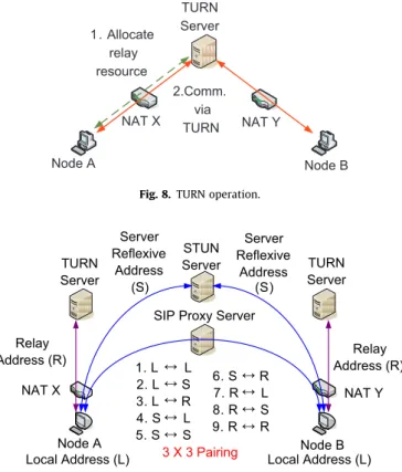
TURN (Rosenberg et al., 2010; Maenpaa et al., 2010; Bae and Cho, 2010) utilizes a relay node in the public domain to bridge together two sessions independently created by two hosts behind different NATs. AsFig. 8illustrates, Node A connects to a TURN server to request relay resource and inform Node B of the relay resource. Once two hosts wish to communicate with each other, they can relay their data through the TURN server.
ICE (Rosenberg, 2010; Maenpaa et al., 2010) uses a set of methods, including STUN and TURN, for NAT transversal. Rather than choosing between STUN and TURN for a particular session request, a host uses both techniques simultaneously to obtain a set of IP addresses and ports (Fig. 9). The addresses and ports include the one on a directly attached network interface (local address), the translated one on the external side of a NAT (server-reflexive address), and the one allocated from a TURN server (relay address). Each address and port represents a potential point of communications for the host. Both hosts exchange three candidate addresses after obtaining them, making total nine candidate communicating pairs. A connectivity check is then performed for each pair to see if a session can be successfully established between the pair.
A complete test of nine connectivity checks incurs considerable delays and message overhead. Furthermore, ICE may fail to detect some direct communication paths due to the lack of priori knowl-edge about connection tracking. In ICE, a callee collects all candi-dates of both peers before a caller does because the caller encapsulates three candidate transport addresses in the session request. Therefore, the callee will send a connectivity check request for the mapped-address pair earlier than the caller. Suppose that the caller and callee inFig. 9are nodes A and B, respectively, and NAT X
is a ConTrack NAT. NAT X not only drops the connectivity check request sent by node B, but also blocks the original mapped-address and assigns a new one for the request sent by the caller. As a result, ICE leaves much room for improvement.
MOSAIC (Mao et al., 2012) provides a variety of services on a shared overlay infrastructure, one of which is NAT traversal. This infrastructure of MOSAIC allows coexistence of several overlay networks. In this architecture, a resilient overlay network (RON), which works for nodes that have publicly routable IP addresses, can be placed on the top of another overlay protocol that enables NAT traversal. Nodes behind NATs can thus be able to join the RON network to relay their data packets.
GPA (Cuevas et al., 2010) suggests that Relay is the easiest solution to NAT traversal problem and attempts to select a topologically close-by Relay for the hosts behind NATs to mini-mize both the delay of the relayed communication and the transit traffic generated by the Relay. It attempts first a Relay residing in the same Autonomous System (AS) and then the one within the same country. If both fail, the GPA tries one in the host’s continent and finally, a Relay is randomly chosen.
Houngue et al. (2011) proposed a solution to allow SIP-based communications in P2P network. The solution inHoungue et al. (2011) utilizes a server to store client’s public contact information (mapped-address) instead of its private address. By consulting the server before each transmission, this approach allows each client or proxy to always send SIP signaling message to the correct address. This approach also uses a Relay located in the public network to enable exchange of media flow between two SIP clients behind NATs.
UPnP (Boucadair et al., 2011) is a set of networking protocols that allows networked devices, such as personal computers and home gateways, to discover each other’s presence and establish services for communications. UPnP can provide further assistance with NAT traversal. Internet gateway device (IGD) protocol (Boucadair et al., 2011) is an NAT traversal method implemented via UPnP. Routers and firewalls exposing themselves as IGDs allow local UPnP clients to perform a variety of actions upon them, including retrieving the external IP address of the IGD, enumerating existing port mappings, and adding or removing port mappings. By adding a port mapping, a UPnP client behind an IGD can enable the traversal of the IGD from an external address to an internal client.
ANT (Patro et al., 2011) utilizes audio signaling for NAT traversal and allows two mobile clients to establish a direct connection with minimal user intervention and without connecting to an intermediate server. ANT uses UPnP to obtain configuration information for NAT traversal. Such information is encoded using different audio frequen-cies, converted to audio sounds, and transmitted through the users’ phones. The remote client receives the audio samples by phone and converts them back into NAT traversal configuration data.
Chen and Jia (2009) attempted to redesign a new NAT framework to accommodate NAT problems all at once. NATng (Chen and Jia, 2009) is framework that includes a bidirectional NAT and a Domain Name System Application Level Gateway (DNSALG) for providing private address name resolutions and hole punching control func-tion. These components coordinate and provide bidirectional access capability between intranet and internet. NATng allows clients with private IP address to share a single public IP address to access the whole Internet via traditional NAT mechanism; it also supports clients with public IP address to access the whole intranet via fully qualified domain name (FQDN) addressing mechanism.
3. Context aware NAT (CAN) traversal scheme
The basic idea of CAN is that we need not perform all sorts of connectivity checks for two hosts behind NATs to communicate.
NAT X NAT Y Node B Node A 1. Allocate relay resource 2.Comm. via TURN TURN Server
Fig. 8. TURN operation.
Server Reflexive Address Server Reflexive Address (S) (S) 3 X 3 Pairing 1. L L 2. L S 3. L R 4. S L 5. S S 6. S R 7. R L 8. R S 9. R R TURN Server TURN Server NAT X NAT Y Relay
Address (R) Address (R)Relay
SIP Proxy Server STUN Server
Node A Node B
Local Address (L) Local Address (L) ↔ ↔ ↔ ↔ ↔ ↔ ↔ ↔ ↔
We can utilize prior knowledge about network context to selec-tively perform promising connectivity check. To this end, hosts behind NATs implement a software module (namely, user agent or UA) to collect their network-context information. The informa-tion includes host locainforma-tion (public/private domain), NAT type (mapping behavior and filtering behavior), whether hairpin translation is supported, and whether connection tracking is implemented. When both hosts wish to setup a session, both UAs exchange network-context information through an indepen-dent signaling protocol such as SIP. Based on the information, the UAs then determine the most suitable communicating paths and the host to initiate the connectivity checks. The following para-graphs illustrate the operations of CAN with signaling protocol SIP (Fig. 10).
1. The first step of CAN is to collect network-context information. When a host initiates its VoIP UA, the UA starts collecting and storing network-context information. Such information includes host location (public or private domain), NAT type (FC, AR, PR, or SY), whether hairpin translation and/or connec-tion tracking is enabled.
2. The second step is to exchange network-context information. When a host wishes to contact another host, both can use an out-of-band signaling protocol to exchange network-context information. In case of SIP, the caller uses an INVITE message to carry its network-context information, while the callee uses 200 OK.
3. After acquiring complete NAT information, both hosts run CAN Connectivity Check Algorithm (CCCA) to choose a candidate path and initiator for connectivity check. CCCA is described in the next subsection.
4. The last step of CAN establishes the session so that hosts can start transferring data.
3.1. CAN connectivity check algorithm (CCCA)
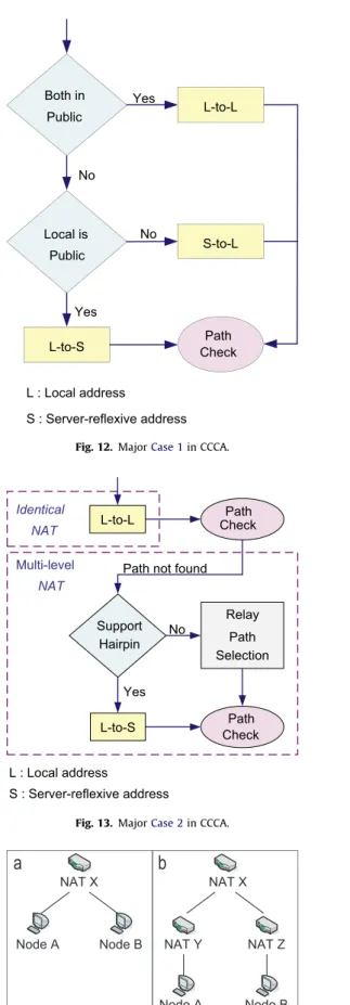
The CCCA uses network-context information to determine which paths to be tested and the initiator to start connectivity check. AsFig. 11shows, CCCA differentiates four different cases and tailors a specific connectivity check procedure for each case.
1. Case 1corresponds to the condition that at least one host is in the public domain.
2. Case 2 corresponds to the condition that no host is in the public domain but both hosts have an identical
server-reflexive address (i.e., NAT’s external IP address), which means that both hosts are behind the same NAT.
3. Case 3 indicates that the two hosts have different server-reflexive addresses but have identical NAT information. These two hosts may be behind the same NAT because some NATs have multiple public mapping addresses.
4. Case 4 indicates the condition that both hosts are not in the public domain; neither do they have identical server-reflexive address or NAT information.
The following details how these four cases are treated in CCCA.
Case 1. indicates that at least one host is in the public domain. If both hosts are in the public domain, both can use their local (public) addresses to proceed with the connectivity check. If only one host is in the public domain, the host behind a NAT must use its server-reflexive address to initiate a connectivity check, while the other can use its local address. Refer toFig. 12for the treatment. Even inCase 1, the original ICE tests the nine candidate pairs. As a result, it induces longer delays and more messages. The CCCA tests only one candidate pair and thus reduces both delay and message exchanges.
Case 2. covers the cases that both hosts have identical server-reflexive address and are behind the same NAT (Fig. 13). However, this condition does not necessarily imply that these two hosts can use their local (private IP) addresses to perform the connectivity check. AsFig. 14illustrates, there are two possible topologies in
Case 2. The use of local addresses is only possible in the first topology (Fig. 14a).
Caller NATX STUN Server SIP Proxy STUN Server NAT Y Callee
3 . 1 .
2 .
4 .
CAN Connectivity Check
RTP Data
NAT Info. collection NAT Info. collection
Invite (NAT X info.) Invite (NAT X info.) 200 OK (NAT Y info.) 200 OK (NAT Y info.)
Fig. 10. CAN operation with SIP-based VoIP.
Yes Yes No No Yes Both under NAT Identical NAT IP Identical NAT Info.
Both Under NATs Case 1
(Public Domain)
Case 4 (DifferentNAT)
Case 3 (Identical NAT Info.) Case 2
(Identical NAT) Start
No
In the second topology (Fig. 14b), Nodes A and B cannot route packets to each other using local (private IP) addresses because they connect to different NATs (NAT Y and NAT Z). However, if the outmost NAT (NAT X) supports hairpin translation, then both hosts
can use its local address and the server-reflexive address of the other peer to check connectivity. If hairpin translation is not supported, the assistance from a relay server (TURN server) is inevitable. AsFig. 15
illustrates, if the outmost NAT (NAT X) is a SY NAT or adopts connection tracking, then both hosts must use their relay addresses to perform the connectivity check. This is because NAT changes mapping for each session, rendering previously exchanged addresses useless. Otherwise, one host can use the server-reflexive address to perform the connectivity check, while the other uses the relay address. CCCA designates the caller as the one to use the server-reflexive address. This approach also reduces the usage of the relay server and the latency between hosts.
Case 3. considers the condition that hosts have identical network-context information (Fig. 16). There can be three possible topologies asFig. 17illustrates. No Caller Symmetric/ ConTrack NAT S-to-R R-to-S R-to-R Yes Yes No L : Local address S : Server-reflexive address R : Relay address
Fig. 15. Case for relay path selection. No No Yes Yes Both in Public Local is Public Path Check L-to-L L-to-S S-to-L L : Local address S : Server-reflexive address
Fig. 12. MajorCase 1in CCCA.
No Path not found Identical NAT Support Hairpin Path Check L-to-L L-to-S Relay Path Selection Multi-level NAT Yes L : Local address S : Server-reflexive address Path Check
Fig. 13. MajorCase 2in CCCA.
NAT Y NAT Z NAT X NAT X Node A Node A Node B Node B
Fig. 14. Two possible topologies inCase 2. (a) Identical NAT and (b) Multi-level NAT.
Path not found
Path not found
Path Check S-to-S L-to-L Relay Path Selection L : Local address S : Server-reflexive address Path Check Path Check
Figure 17a shows one possible case when hosts have identical network-context information but different server-reflexive addresses: the NAT has multiple public addresses. Since commu-nications with local addresses consumes least resource in this case, CCCA gives local-to-local (L-to-L) address pair the highest priority in connectivity check (Fig. 16). In the other topologies as shown in
Fig. 17b and c, CCCA tries the candidate pair of two server-reflexive addresses with priority. The relay path is chosen only when CCCA fails to find a communication path with server-reflexive address. Consequently, at most three address pairs are tested.
Case 4. involves the cases that hosts are behind different NATs with different NAT information and only one candidate pair is tested as shown inFig. 18. Combination 1 contains two SY NATs. Since a SY NAT generates different mapped-addresses for differ-ent sessions, hosts behind SY NATs cannot acquire effective mapped-addresses for connectivity check. As a result, both hosts should check connectivity with relay addresses.
Combination 2 and 3 each contains a PR ConTrack NAT and a SY NAT. As mentioned inSection 2.1, a host behind the ConTrack NAT should initiate connectivity check. However, the host behind
the SY NAT cannot acquire an effective mapped-address for the host behind the ConTrack NAT and thus both hosts should check connectivity with relay addresses.
There are two PR ConTrack NATs in Combination 4. Both NATs track and filter out packets according to EH’s IP addresses and port numbers. Since both hosts cannot initiate connectivity check at the same time, they should proceed to check connectivity with relay addresses. However, for the combination with an AR Con-Track NAT and a PR ConCon-Track NAT, a direct communication path is possible. Since an AR ConTrack NAT only tracks and filters out packets with respect to EH’s IP addresses, both hosts could use their server-reflexive addresses to check connectivity and estab-lish a direct communication path as long as the host behind the PR ConTrack NAT initiate connectivity check first.
Combination 5 and 6 each includes a SY NAT and PR NAT. Only the host behind the SY NAT should use a relay address to perform the connectivity check. The host behind the PR NAT can use a server-reflexive address. This is because sessions from the same internal IP address and port generate an identical mapped-address at the PR NAT. As for the cases not mentioned above, the candidate pair of server-reflexive addresses can be used for connectivity check.
3.2. Cost analysis
This subsection analyzes the cost of the proposed approach. The cost includes the number of messages required to collect network-context information, the space needed by SIP INVITE and 200 OK messages when carrying network-context information, and the number of protocol messages required by CCCA.
UA in host need to collect the following information: host location (public/private domain), NAT type (mapping behavior and filtering behavior), whether hairpin translation is supported, and whether connection tracking is implemented.
1. A host can determine its location by its local address directly with negligible cost.
2. There are three types of NAT mapping behaviors (Fig. 2) and three types of NAT filtering behaviors (Fig. 3). To determine the type of the NAT mapping behavior, an IH needs to send three messages to a STUN server, one for each type (Fig. 19a). STUN server responds to each message with the mapped-address it observes. These responses suffice for the IH to make a conclusion. Testing the type of NAT filtering behavior is similar (Fig. 19b): it needs three messages from an IH to a STUN server and three corresponding replies. Therefore, total twelve messages are needed to detect NAT type.
3. Only one message is needed to test whether a NAT supports hairpin translation. After obtaining the server-reflexive address, NAT Y NAT Z NAT Y NAT Z
NAT X NAT X
Node A Node B
Node A Node B Node A Node B
In te rn e t
Fig. 17. Three possible topologies inCase 3. (a) NAT with multi-interface; (b) Identical outmost NAT and (c) Hosts behind separate NATs.
No No Yes Yes Yes No 5.(SY,PR) Path Check 1.(SY,SY) 2.(SY,PR/CT) 3.(PR/CT,SY) 4.(PR/CT,PR/CT) R-to-S S-to-R R-to-R 6.(PR,SY)
PR : Port-Restricted Cone NAT SY : Symmetric NAT
CT : Connection Tracking NAT
S : Server-reflexive address R : Relay address
S-to-S
the host sends one message to its server-reflexive address and checks if the NAT directs such message back to it (Fig. 19c). 4. A host can check if its NAT implements connection tracking
with the help of a STUN server. AsFig. 19d illustrates, Host A sends the first echo request to Port1 on STUN server and STUN server responds the mapped-address to Host A from Port1. Host A then sends the second echo request to Port1 of STUN server and STUN server responds the mapped-address from Port3. Finally, Host A sends the third echo request to Port1 of STUN server and STUN server responds the mapped-address from Port1 again. If the mapped-addresses in the first and third responses are different, NAT X is a ConTrack NAT. Otherwise, NAT X is a regular one. This test generates six messages. However, the first and second messages also serve as a part of the procedure to check the type of the NAT filtering behavior. Therefore, only two additional messages are required (for the third echo request) in this test.
The number of protocol messages for the collection of network-context information is 15 including 12 for NAT type, one for hairpin translation and two for connection tracking. A host can keep obtained information for subsequent sessions as long as it stays behind the same NAT device. When a host moves to the realm of another NAT, the host should renew the network-context informa-tion and inform the remote peer of the update.
Hosts wishing to communicate use an out-of-band signaling protocol such as SIP to exchange network-context information. This information occupies only four bytes in the application payload of a packet, including one for private/public domain, one for NAT type, one for hairpin translation and one for connection tracking. As a result, the cost for delivering such information is insignificant.
The cost of executing CCCA depends on the network-context of both hosts.Table 1shows the number of candidate paths that are checked before a communication path is established for every possible NAT type combination. For example, a caller and a callee behind different AR NAT with identical network-context information
will try path L-to-L followed by path S-to-S and establish a direct communication with path S-to-S according toCase 3of CCCA. In this example, CAN checks two candidate paths while ICE searches all (nine) paths. Since each connectivity check for both hosts can be viewed as a four-way handshake, CCCA saves 36–8¼28 messages. In fact, the execution cost of CCCA is lower than that of ICE in every case.
4. Experimental results
To study the performance of the proposed approach and compare it with that of other alternative, we conducted extended experiments with off-the-shelf NAT devices.Table 2lists all the 17 products tested in our experiments. The alternative we considered is ICE. ICE tests the applicability of nine candidate paths without prior knowledge about network-context informa-tion. In these experiments, we assume the caller of ICE always sends its candidate addresses with session request to callee, thus callee can always start checking connectivity first.
We are interested in direct communication ratio (DCR), con-nectivity check delay, and resource demand (i.e., the number of connectivity check messages). The following paragraphs describe the experiment setup and then present the experimental results.
4.1. Experiment environment setup
Since our experiments use 17 NAT devices, which results in total 17n17 ¼289 possible NAT combinations for caller–callee
pairs, manually setting up and running experiments, and collect-ing the results can be tedious and error prone. Therefore, we designed a fully mesh test bed as shown inFig. 20for a systematic performance measurement. Caller and callee in this test bed can independently select and switch to one NAT device.
Host A NAT X
STUN Server IP1
IP2 Host A NAT X
STUN Server IP1 IP2 Host A NAT X IP1 IP2 STUN Server Host A NAT X Port 1 Port 2 Port 3 Port 1 Port 2 Port 3 Port 1 Port 2 Port 3
Fig. 19. Network-context collection. (a) Mapping Behavior Test; (b) Filtering Behavior Test; (c) Hairpin Translation and (d) Connection Tracking Test.
Table 1
Number of candidate paths tested for each NAT combination. Callee FC AR AR/CT PR PR/CT SY Caller FC 2 1 1 1 1 1 AR 1 2 1 1 1 1 AR/CT 1 1 2 1 1 1 PR 1 1 1 2 1 1 PR/CT 1 1 1 1 3 1 SY 1 1 1 1 1 3 Table 2
NAT devices used in the experiments.
No. Brand Model No. Brand Model
1 D-Link DI-604 10 Lemel LM-WLG6400
2 SMC SMCWBR14-G2 11 Linux Iptables
3 Linksys WRT150N 12 3Com 3CRWER100-75
4 Corega CG-BARMX2 13 AboCom FSM410
5 Planex BLW-54MR 14 Asus RX3041
6 SMC SMCWGBR-14N 15 Netgear PR614
7 Belkin F5D8231TW4 16 Zyxel P334
8 Draytek Vigor 2104P 17 FreeBSD Pf 9 Edimax BR-6204WG
4.2. Direct communication ratio (DCR)
We first examined the behaviors of all NAT devices.Table 3
shows the results of each device. With these results, two hosts can choose the proper candidate path to check connectivity.
Figure 21indicates whether a direct communication path can be established between each caller–callee pair. A shaded area in
Fig. 21 indicates that both CAN and ICE can establish a direct communication path for the corresponding caller–callee pair, while a blank area means that neither CAN nor ICE can. Each star
sign indicates a caller–calle pair for which only CAN could establish a direct communication path. The DCR of CAN is 209/ 289¼72.32%, 7.27% higher than that of ICE (188/289¼65.05%). The major difference is that CAN can manage ConTrack NAT (NATs 3, 9, and 11) well with initiator-change, while connection tracking remains a problem for ICE. Since the callee will initiate connec-tivity check first in ICE, if the caller is behind a ConTrack NAT, then the session request will be filtered out by caller’s NAT.
4.3. Connectivity check delay
We also measured average connectivity check delay for each type of NAT combinations. The results are shown in Table 4
(observed by caller) andTable 5 (observed by callee). Although CAN needs to collect network-context information, it can save and reuse such information in subsequent connectivity checks. Thus, the information gathering delay is not considered: we assume that both the caller and callee have already exchanged their NAT information. The experimental results show that the average delays of the caller and the callee in ICE are 4.24 s and 4.43 s, respectively. The results of CAN show 0.13 s average delay of the caller and 0.45 s average delay of the callee. The time that a caller takes for connectivity check in ICE is more than 32 times longer than that in CAN, and a callee in ICE takes a time almost 10 times longer than that taken in CAN. This is because ICE performs connectivity checks sequentially for all candidate paths, whereas CAN reduces unnecessary delay by using network-context infor-mation to selectively perform connectivity checks.
4.4. Resource demand
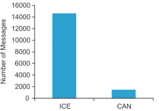
Figure 22 shows the total number of protocol messages required by CAN and ICE for connectivity checks. An unsuccessful connectivity check requires six messages, while a successful one takes 4–6 messages (depending on the type of the NAT pair under check). Our results reveal that the number of messages needed by CAN is much fewer than that of ICE because ICE performs connectivity checks for all possible candidate paths, while CAN selects some paths for connectivity checks. Experimental results
NAT 1 NAT 2 NAT 3 NAT 17
Caller Callee
Internet
Fig. 20. Topology adopted in the experiments.
Table 3
NAT behavior of each device. NAT No. Test results
NAT type Hairpin ConTrack
1, 2 FC Yes No 6 AR Yes No 3 AR No Yes 4, 5 AR No No 8 PR Yes No 9, 11 PR No Yes 7, 10, 12 PR No No 14, 15, 16, 17 SY No No
Fig. 21. The direct communication status of all NAT combinations of ICE/CAN.
Table 4
Average connectivity check delay observed by the caller. Callee
FC AR PR SY
CAN ICE CAN ICE CAN ICE CAN ICE Caller FC (s) 0.01 4.10 0.03 4.28 0.01 4.26 0.15 4.23
AR (s) 0.03 4.26 0.01 4.19 0.41 4.32 0.54 4.34 PR (s) 0.02 4.24 0.01 4.29 0.38 4.33 0.01 4.08 SY (s) 0.01 4.18 0.01 4.28 0.01 4.31 0.01 4.07
Table 5
Average connectivity check delay observed by the callee. Callee
FC (s) AR (s) PR (s) SY (s)
CAN ICE CAN ICE CAN ICE CAN ICE Caller FC 0.32 4.33 0.35 4.46 0.33 4.45 0.47 4.50
AR 0.36 4.50 0.34 4.50 0.33 4.50 0.48 4.45 PR 0.35 4.50 0.34 4.50 0.34 4.50 0.34 4.30 SY 0.33 4.50 0.34 4.49 0.33 4.49 0.34 4.08
indicate that ICE produces almost ten times the connectivity check messages than that of CAN.
5. Conclusion
This study proposes Context Aware NAT (CAN) traversal scheme that not only reduces the delay and messages, but also considers ConTrack NAT. In addition, CAN has a higher DCR than ICE, and thus reduces the usage of the relay server. The CAN hosts collect and store network-context information at the beginning of the user programs. When performing connectivity checks, both hosts exchange their stored information to help eliminate unne-cessary checks. This exchange decreases the latency and reduces the number of message exchange between hosts. Experimental results show that CAN outperforms ICE in terms of DCR, con-nectivity check delay, and resource demand.
Acknowledgments
This work was supported in part by National Science Council, Taiwan, under Grants NSC 100–2221-E-009–072-MY3 and NSC 101–2219-E-009–028, and D-Link Co., Taiwan.
References
Audet F, Jennings C. Network Address Translation (NAT) Behavioral Requirements for Unicast UDP. Internet Engineering Task Force – Request for Comments 2007;4787.
Aurel Constantinescu, M, Croitoru, V., Oana Cernaianu, D, NAT/firewall traversal for SIP: issues and solutions. In: International symposium on signals, circuits and systems, vol. 2; 2005. p. 521–4.
Bae, K; Cho, K., The problems and their solutions when using SIP in NAT environment. In: Fifth international conference on computer sciences and convergence information technology; 2010. p. 997–1000.
Boucadair, M, Penno, R, Wing, D, Dupont, F., Universal plug and play (UPnP) internet gateway device (IGD)-port control protocol (PCP) interworking function. IETF Draft draft-bpw-pcp-upnp-igd-interworking-02; 2011.
Chen Y-C, Jia W-K. Challenge and solutions of NAT traversal for ubiquitous and pervasive applications on the Internet. The Journal of Systems & Software 2009;82(10):1620–6.
Cuevas R, Cuevas A´, Cabellos-Aparicio A, Jakab L, Guerrero C. A collaborative P2P scheme for NAT Traversal Server discovery based on topological information. Computer Networks 2010;54(12):2071–85.
Ford, B, Srisuresh, P, Kegel, D., Peer-to-peer communication across network address translators. In: USENIX annual technical conference; 2005. p. 179–92. Francis, P, Egevang, K., Traditional IP network address translator (Traditional NAT),
Internet Engineering Task Force – Request for Comments 3022 (2001). Ho C-Y, Tseng C-C, Wang F-Y, Wang J-T, Lin Y-D. To call or to be called behind
NATs is sensitive in solving the direct connection problem. IEEE Communica-tions Letters 2010;15:94–6.
Ho C-Y, Wang F-Y, Tseng C-C, Lin Y-D. NAT-Compatibility testbed: an environment to automatically verify direct connection rate. IEEE Communications Letters 2011;15(1):4–6.
Houngue, P, Damiani, E., Glitho, R., Overcoming NAT traversal issue for SIP-based communication in P2P networks. In: Fourth joint IFIP wireless and mobile networking conference; 2011. p. 1–8.
Huang, C-L; Hwang, S-H., The asymmetric NAT and its traversal method. In: IFIP international conference on wireless and optical communications networks; 2009. p. 1–4.
Kuramochi, K, Kawamura, T, Sugahara, K., NAT traversal for pure P2P e-learning system, In: Third international conference on internet and web applications and services; 2008. p. 358–63.
Lin Y-D, Tseng C-C, Ho C-Y, Wu Y-H. How NAT-compatible are VoIP applications? IEEE Communications Magazine 2010;48(12):58–65.
Maenpaa, J, Andersson, V, Camarillo, G, Keranen, A., Impact of network address translator traversal on delays in peer-to-peer session initiation protocol. In: 2010 IEEE global telecommunications conference; 2010. p. 1–6. Mao Y, Loo B-T, Ives Z, Smith J-M. MOSAIC: declarative platform for dynamic
overlay composition. Computer Networks 2012;56(1):64–84.
Meng, X-J; Chen, R.. Petri net modeling of SIP of traversing NAT based on STUN. In: International conference on computer science and electronics engineering, vol. 3; 2012. p. 134–8.
A. Patro, Y. Ma, F. Panahi, J. Walker, S. Banerjee, A system for audio signaling based NAT Traversal. In: Third international conference on communication systems and networks; 2011. p. 1–10.
Raste TM, Kulkarni DB. Design and implementation scheme for deploying IPv4 over IPv6 tunnel. Journal of Network and Computer Applications 2008;31:66–72.
Rosenberg J. Interactive connectivity establishment (ICE): a protocol for network address translator (NAT) Traversal for offer/answer protocols. Internet Engi-neering Task Force – Request for Comments 2010;5425.
Rosenberg J, et al. SIP: session Initiation protocol. Internet Engineering Task Force – Request for Comments 2002;3261.
Rosenberg, J, Weinberger, J, Huitema, C., Mahy, R., STUN – simple traversal of user datagram protocol (UDP) through network address translators (NATs). Internet Engineering Task Force – Request for Comments 3489 (2003).
Rosenberg J, Weinberger J, Huitema C, Mahy R. Session traversal utilities for NAT (STUN). Internet Engineering Task Force – Request for Comments 2008;5989. Rosenberg J, Mahy R, Matthews P, Huitema C. Traversal using relays around NAT (TURN): relay extensions to session traversal utilities for NAT (STUN). Internet Engineering Task Force – Request for Comments 2010;5766.
Saikat, G, Yutaka, T., Paul, F., NUTSS: a SIP-based approach to UDP and TCP network connectivity. In: Proceedings of the ACM SIGCOMM workshop on future directions in network architecture; 2004.
Srisuresh P, Ford B, Kegel D. State of peer-to-peer (P2P) communication across network address translators (NATs). Internet Engineering Task Force – Request for Comments 2008;5128.
Stegel T, Sterle J, Sedlar V, Bester J, Kos A. SCTP multihoming provisioning in converged IP-based multimedia environment. Computer Communications 2010;vol. 33(14):1725–35.
Yoshimi H, Enomoto N, Cui Z, Takagi K, Iwata A. NAT Traversal Technology of reducing load on relaying server for P2P connections. Consumer Communication and Network Conference 2007:100–4.
0 2000 4000 6000 8000 10000 12000 14000 16000 ICE CAN Numbe r of Mes s ages