國
立
交
通
大
學
資 訊 學 院
資 訊 科 學 與 工 程 研 究 所
博
士
論
文
多執行緒多處理器網路處理器之資源分配--針對計算密集及記憶體存取密集的網路應用
程式
Resource Allocation in Multithreaded Multiprocessor
Network Processors for Computational Intensive and
Memory Access Intensive Network Applications
研 究 生:林義能
指導教授:林盈達 博士
多執行緒多處理器網路處理器之資源分配--針對計算密
集及記憶體存取密集的網路應用程式
Resource Allocation in Multithreaded Multiprocessor
Network Processors for Computational Intensive and
Memory Access Intensive Network Applications
研 究 生:林義能 Student:Yi-Neng Lin
指導教授:林盈達 Advisor:Ying-Dar Lin
國 立 交 通 大 學
資 訊 科 學 與 工 程 研 究 所
博 士 論 文
A Dissertation Submitted to Department of Computer ScienceCollege of Computer Science National Chiao Tung University
for the Degree of Doctor of Philosophy
in
Computer Science July 2007
Hsinchu, Taiwan, Republic of China
多執行緒多處理器網路處理器之資源分配--針對計算密
集 及 記 憶 體 存 取 密 集 的 網 路 應 用 程 式
學生:林義能
指導教授:林盈達
國立交通大學資訊科學與工程研究所博士班
摘
要
今日網路應用程式之處理需要強大的硬體平台以應付日益龐大的
計算量以及記憶體存取。此平台亦必須能夠隨著協定或產品規格
之變動而作有效的調整。沿用已久的多用途處理器架構,其效能
往往被“核心-使用者程式”間的溝通以及執行緒轉換的負擔拖
累;而常用的 ASIC 解決方式則受限於開發時程過久且調整不易的
缺陷而無法滿足需求。
本篇論文主要探討(1)應用日益盛行的網路處理器架構來加速網路
網路封包處理的可行性,此網路處理器包含多個處理器且每個處
理器包含多個硬體執行緒,具有豐富硬體資源、較小的執行緒轉
換負擔以及可調整性等優點,和(2)用此平台來處理不同計算或記
憶體存取量的網路應用程式時硬體資源的分配。我們首先檢視各
種不同的網路處理器並將其分成“助理處理器為主”和“核心處
理器為主”兩大類。就前者而言,助理處理器負責占封包處理主
要工作的資料面象部分,而後者則是由核心處理器兼顧所有的控
制面象和大部分的資料面象的處理。之後我們針對計算密集以及
記憶體存取密集的網路應用程式分別用“助理處理器為主”和
“核心處理器為主”的兩種網路處理器來實作並評估其效能。最
後,根據實作的經驗我們進一步設計出其數學模型以及模擬環
境,以期能找出設計、使用此二種架構時的參考。
Resource Allocation in Multithreaded Multiprocessor
Network Processors for Computational Intensive and
Memory Access Intensive Network Applications
Student: Yi-Neng Lin
Advisor: Dr. Ying-Dar Lin
Institute of Computer Science and Engineering
College of Computer Science
National Chiao Tung University
Abstract
Networking applications today demand a hardware platform with
stronger computational or memory access capabilities as well as the
ability to efficiently adapt to changes of protocols or product
specifications. Being the ordinary options, however, neither a general
purpose processor architecture, which is usually slowed down by
kernel-user space communications and context switches, nor an ASIC,
which lacks the flexibility and requires much development period,
measures up.
In this thesis, we discuss (1) the feasibility of applying the emerging
alternative, network processors featuring the multithreaded
multiprocessor architecture, rich resources, minor context switch
overhead, and flexibility, to solve the problem, and (2) the ways of
exploiting those resources when dealing with applications of different
computational and memory access requirements. We start by
surveying network processors which are then categorized into two
types, the coprocessors-centric and the core-centric ones. For the
former, the coprocessors take care of the data plane manipulation
whose load is usually much heavier than the one of the control plane,
while in the latter the core processor handles the most part of packet
processing, including the control plane and data plane. After that we
evaluate real implementations of computational intensive and memory
access intensive applications over the coprocessors-centric and
core-centric platforms, respectively, aiming to unveil the bottlenecks
of the implementations as well as the allocation measures. Finally,
based on the evaluations, analytical models are formalized and
simulation environments are built to observe possible design
implications for these two types of network processors.
致 謝
回首研究生生涯,從剛開始的懵懂,到後來終於培養出自己
的一套做事方法與態度,這都必須歸功於我的指導老師 林盈達教
授。也正是因為他的教誨、包容與鼓勵,遇到困難的時候總能夠
一路披荊斬棘,也及時導正了方向。在此,我要誠摯地表達出對
林老師的感謝。
高速網路實驗室學長學弟們的討論與扶持也是這幾年來重要
的支撐。謝謝賴源正學長、尹維銘學長、曹世強學長、林柏青、
曾國坤以及學弟們,讓我能夠感受到滿滿的情誼。
最後要感謝家人(爸爸媽媽妹妹弟弟)這幾年來精神上的支
持。融洽的家庭氣氛對於我情緒與壓力的排解有著非常正面的幫
助。謝謝子晴、筱玲、和佳筠,你們的陪伴與傾聽讓我有堅持到
最後的力量。你們是我永遠的家人。
Contents
1. Introduction... 7
1.1 Challenges of Hardware Platforms for Modern Networking Applications ... 7
1.2 The Importance of Resource Allocation for Network Processors... 8
1.3 Coprocessors-centric and Core-centric Network Processors ... 8
1.4 Related Works ... 9
1.4.1 Application Design and Implementation···10
1.4.2 Mathematical Modeling and Simulation ···11
1.5 Thesis Objective and Dissertation Road Map ... 12
2. Research Methodologies ... 14
2.1 Application Design and Implementation... 14
2.2.1 Software Architecture of IXP425 ···14
2.2.2 Software Architecture of IXP2400···15
2.2.3 Performance Benchmark ···16
2.2 Mathematical Modeling and Simulation... 17
3. Resource Allocation of the Coprocessors-centric Network
Processors for Memory Access Intensive Applications... 19
3.1 Introduction ... 19
3.2 Hardware Platform (IXP2400) ... 20
Detailed Packet Flow in IXP2400 ···22
3.3 Problem Statements... 23
3.4 Design and Implementation ... 24
3.4.1 NIDS Briefing···24
3.4.2 Design Issues ···25
3.4.3 Mapping Processing Stages to the Hardware Platform ···26
3.4.4 Algorithms Adopted and Packet Inspection ···28
3.5 System Benchmark and Bottleneck Analysis... 30
3.5.1 Benchmark Setup ···30
3.5.2 Effect of Improper ME/Thread Allocations ···31
3.5.3 Estimating the Optimal (I,J) Pair ···33
3.6 Summary ... 36
4. Coprocessors-centric Network Processors: Analysis, Simulation, and
Design Implications ... 38
4.1 Introduction ... 38
4.2 Effect of Different Thread Allocation Schemes ... 39
4.3 Overview of the Analytical Model... 41
4.4 Markov Chain Formalization ... 42
4.4.1 State Definition and State Space Determination···42
4.4.2 Determination of the Status Transition Diagram and State Transition Matrix ···44
4.4.3 Determination of the State Transition Matrix···46
4.4.4 Performance Estimation for the Analytical Model ···48
4.5 Simulation and Analytical Model validation ... 49
4.5.1 Design of the Petri Net Based Simulation Environment···49
4.5.2 Model Validation By the Simulation···52
4.5.3 Simulation Setup···53
4.5.4 Effect of the RSS Memory Queuing Discipline ···54
4.5.5 Unbalanced Load among Threads···55
4.5.6 Simulations with Three P-M Ratios···56
4.5.7 Solutions for the Memory Bottleneck ···59
4.6 Summary ... 60
5. Resource Allocation of the Core-centric Network Processor for
Computational Intensive Applications... 63
5.1 Introduction ... 63
5.2 Hardware Platform (IXP425) ... 65
5.2.1 Hardware Architecture of IXP425 ···65
5.2.2 Detailed Packet Flow in IXP425 ···66
5.2.3 Software Architecture of IXP425 ···66
5.3 Processing Stages Analysis and Offloading Schemes Design... 68
5.3.1 VPN Briefing ···68
5.3.2 Identifying Offloading Candidates···69
5.3.3 Implementation ···70
5.4.1 System Benchmark Setup···71
5.4.2 Scalability Test···72
5.4.3 Bottleneck Analysis···74
5.4.4 Turnaround Time Analysis of Functional Blocks ···77
5.5 Summary ... 78
6. Core-centric Network Processors: Analysis, Simulation, and Design
Implications ... 80
6.1 Introduction ... 80
6.2 Background... 82
6.2.1 Performance Model Overview···82
6.2.2 Architectural Assumptions ···83
6.3 Analytical Model ... 84
6.3.1 The Busy-waiting Model···84
6.3.2 The Interrupt-driven Model ···85
6.4 Simulation Environment... 87
6.5 Evaluation ... 89
6.5.1 Validation of the Analytical Model ···89
6.5.2 Differentiated Run Lengths ···92
6.5.3 Effect of the Context Switch Overhead···93
6.5.4 Benefit from Offloading ···93
6.5.5 Effect of Limited Buffer Sizes···95
6.6. Summary ···96
7. Conclusions... 98
List of Tables
3.1 Performance of (a) A-C and (b) W-M with one and two memory banks. ···35
4.1 Comparison between the homogeneous and heterogeneous schemes.···40
4.2 Activation events. ···47
4.3 The setup of parameters setup in the model validation. ···52
4.4 Validation of the analytical model against the blocking and non-blocking cases ···53
4.5 Different kinds of P-M ratios. ···54
List of Figures
1.1 Coprocessors-centric network processors.··· 6
1.2 Core-centric network processors. ··· 6
1.3 Related works on the network processor resource allocation problem. ··· 7
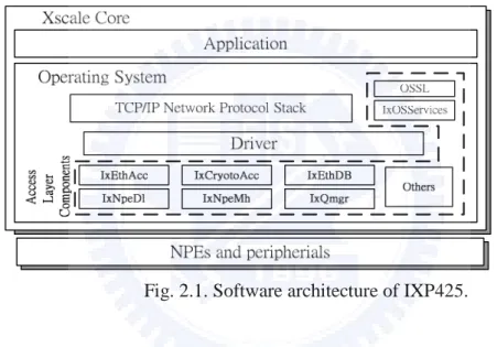
2.1 Software architecture of IXP425. ···12
2.2. Software architecture of IXP2400. ···15
2.3 Benchmark environments for (a) packet forwarding and (b) IPsec. ···16
2.4 Transition diagram of a thread in a multithreaded multiprocessor. ···16
2.5 Petri net of a multithreaded processor. ···18
3.1 Hardware architecture of IXP2400.···20
3.2 Timeline showing two consecutive packets. ···26
3.3 The processing stages of an NIDS on IXP2400. ···27
3.4 Interaction between the thread dispatcher and packet inspector. ···30
3.5 Performance of the (a) A-C and (b) W-M for different (I,J) combinations. ···32
3.6 Profiling of the total (a) memory access cycles and (b) computational cycles.···33
3.7 The performance of A-C and W-M with different numbers of MEs. ···34
4.1 Homogeneous and heterogeneous thread allocations.···40
4.2 The blocking and non-blocking packet processing schemes. ···42
4.3 Status transitions of a thread. ···43
4.4 Status transition rate diagram of Ti,j.···45
4.5 Example state transitions. ···45
4.6 An example hierarchical CPN. ···51
4.7 Effect of different memory queuing disciplines for SF. ···55
4.8 No. of packets in system under different unbalance ratios and no. of threads.···56
4.9 Processor and memory utilizations for the DS and SF. ···56
4.10 Memory access latency and utilization of various numbers of threads. ···57
4.11 Performance relative to (1,3).···58
4.12 Processor and memory efficiencies for different Is. ···58
4.13 Performance improvement from the three solutions. ···60
5.1 Hardware architecture of IXP425.···65
5.2 Software architecture of IXP425. ···68
5.4 Data paths of the four offloading schemes.···72
5.5 Throughput of packet forwarding.···73
5.6 IPSec Throughput: the DES case. ···74
5.7. IPSec Throughput: the 3DES case.···74
5.8 Input traffic load vs. XScale utilization for two packet lengths.···75
5.9 IPSec packet success ratio vs. XScale utilization.···76
5.10 Turnaround time of a cryptographic request for a packet. ···77
5.11 Turnaround time of functional blocks.···78
6.1 Processing flow and task allocation of the VPN application over IXP425. ···83
6.2 The busy-waiting model. ···85
6.3 The interrupt-driven model. ···86
6.4 The Petri net simulation model. ···88
6.5 Run length vs. core utilization.···90
6.6 Analytical model validation against the simulation and real implementation. ···91
6.7 The revised analytical. ···91
6.8 Example state transitions of the revised model. ···92
6.9 Benefits from differentiated run lengths for Core_A and Core_B. ···92
6.10 Core usage distribution for different context switch delays.···93
6.11 Throughput of various offloading schemes.···94
Chapter 1
Introduction
1.1
Challenges of Hardware Platforms for
Modern Networking Applications
Increasing link bandwidth demands faster nodal processing, especially of data-plane traffic. Nodal data-plane processing ranges from routing table lookup to various classifications for firewall, DiffServ and Web switching. The traditional general-purpose processor architecture is no longer sufficiently scalable for wire-speed processing, and some ASIC components or co-processors are commonly used to offload the data-plane processing, while leaving only control-plane processing to the original processor.
Several ASIC-driven products have been announced in the market, such as the acceleration cards for encryption/decryption, VPN gateways, Layer 3 switches, DiffServ routers and Web switches. While accelerating the data-plane packet processing with special hardware blocks, much wider memory buses, and faster execution processes, these ASICs lack the flexibility of reprogrammability and have a long development cycle usually of months or even years. The cost of possible design failures is also high.
Network processors are emerging as an alternative solution to ASICs for providing re-programmability while retaining scalability for data-plane packet processing. A network processor typically consists of one core processor and a number of coprocessors, so that developers can embed the control-plane and data-plane traffic management modules into the core and coprocessors, respectively. Scalability concerns due to the computational and memory access overhead, in data-plane packet processing could be satisfied with the hardware contexts of minor context switching overhead in each of the coprocessors as well
as the instructions specifically for networking.
1.2
The Importance of Resource Allocation for
Network Processors
Though network processor is promising in its scalability and extensibility [LLP02, LLY+03, BH95], the determination of architectural parameters such as numbers of processors, threads in a processor, and memory banks, respectively, is not trivial given a specific application and hardware platform combination. Furthermore, since one proper configuration today may not be suitable tomorrow due to different evolving speeds of manufacturing technologies of the functional units, some general guidelines may be demanded for efficient and appropriate parameter determination.
1.3
Coprocessors-centric
and
Core-centric
Network Processors
Two types of network processors, the coprocessors-centric and core-centric ones, are classified and addressed in the thesis. In the former, a number of coprocessors are used to take care of the data plane manipulation whose load is usually much heavier than the one of the control plane. In the latter the core processor handles the most part of packet processing, including the control plane and data plane; only few coprocessors are required to offload some computational intensive processing.
Since the coprocessors-centric model is used mostly to offload the data plane, especially the memory access intensive processing, for its multithreading architecture, we investigate the resource allocation by implementing the Intrusion Detection and Prevention (IDP) system over the IXP2400 network processor.
As for the core-processor centric model, we implement the Virtual Private Network (VPN) gateway, which needs to offload limited portion of computational intensive operations to the coprocessors, over the IXP425. For both types we also investigate the effect of different architectural parameters through mathematical modeling.
Fig. 1.1. Coprocessors-centric network processors.
Fig. 1.2. Core-centric network processors.
1.4
Related Works
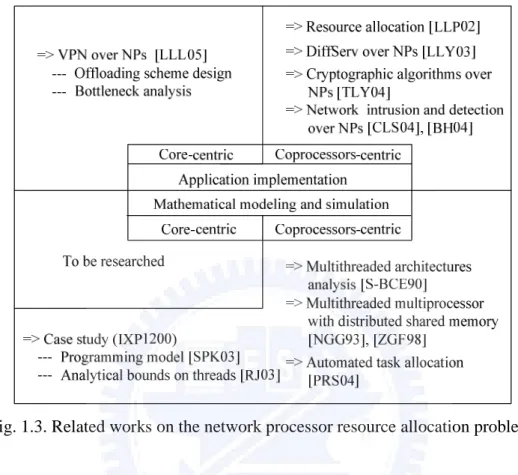
In this chapter, we present some prior groundwork for our thesis. To comply with our research directions mentioned previously, we discuss the related works in two aspects: (1) application implementation and (2) mathematical modeling and simulation. The following is summarized in Fig. 1.3.
Fig. 1.3. Related works on the network processor resource allocation problem.
1.4.1
Application Design and Implementation
For memory access intensive applications, some researches have focused on improving the throughput by the deployment of network processors. Bos and Huang [BH04] implemented an NIDS over the Intel IXP1200 [INT]. The prototype comprises only the receiver and packet processing using the Aho-Corasick [AC75] algorithm, but it does not support inspection of patterns across more than two packets as well as multiple flows. Clark et al. [CLS+04], designed a Network Intrusion Detection and Prevention System (NIDP) utilizing an IXP1200 and an FPGA. The former is for header processing and the latter serves as the signature matching engine, and the bottleneck is found to be the bus connecting them. Nevertheless, those researches did not discuss in detail on proper resource allocations.
only one can be found in the literature [TLY+04]. The authors implement various cryptographic algorithms over the IXP2800 network processor, analyze the instruction mix and compare it with other header processing applications, and finally propose implementation and optimization principles to improve overall performance. They find that the ALU operations occupy a significant share, 79.9%, of the total instruction mix, compared to the 58% of the Commenbench [WF00] PPA (Payload Processing Applciations), 53.5% of the NpBench [LJ03], and 41% of the Commonbench HPA (Header Processing Applications).
The implementation principles, besides some minor techniques, include the flow-level and intra-block-level parallelisms. In the flow-level parallelism in which each thread is allocated to a flow, it is observed that incorporating multiple threads does not necessarily improve the performance but depends on the algorithms. Another reason for the limited improvement is that multithreading is found only help consume more of the stalled cycles rather than the idle ones. To utilize the idle cycles, they use the intra-block level parallelism, in which one main ME (namely processor) and a helper ME are involved in processing a certain block of instructions. The helper ME pre-fetches the data from memory for the later use of the main ME. Some principles are also proposed for optimization such as (1) increasing the cache size on MEs to hold tables, (2) enlarging the memory and command queues and (3) organizing the MEs into a smaller cluster for fast shared-bus performance.
1.4.2
Mathematical Modeling and Simulation
Analytical approaches have been favored in many researches for its capability of fast evaluation of the systems under investigation [SMA03]. However, limited researches have devoted to the modeling of multithreaded multiprocessors. Rafael et al. [S-BCE90] proposed a model to obtain the performance, in terms of processor efficiency, of a multithreaded architecture with varying number of threads. The effect of multiprocessor can be mimicked by adjusting the memory
access latency which is assumed geometrically distributed. This model possesses good abstraction of the architecture; however, the interaction between the processing elements and the memory subsystem is disregarded.
This problem was remedied in [NGG93] by including the memory subsystem in their model, in which the processing elements as well as the memory are distributed and shared. Each thread is capable of a complete packet processing, and has a rate to access local/remote memory modules during processing. Nevertheless, the model is not feasible since the queuing network adopted was a closed one, and thus does not consider the packet arrivals and departures of real networking applications.
A number of recent works concerning the modeling of NPs can be found in [FW02, WT01, GKS03, CFB01, CB02]. Though detailed parameters are included and programming paradigms are analyzed in their models, the discussion and consideration of thread allocation are substantially ignored. Lakshmanamurthy et al. proposed a methodology for analyzing the performance of the Intel IXP2400 [LLP02]. But they focused only on the validation of the system performance, while the processor and memory utilizations are not addressed and no design guidelines are suggested. In [SPK03] and [RJ03], the authors propose a programming model and an analytical method, respectively, for the IXP1200 as a case study. The former considerably accelerates the process of the application implementation and verification; the latter delivers the analytical bounds on the optimum number of threads. Moreover, Gries et al. in [GKS03] uses Network Calculus to model the IPv4 forwarding on the IXP1200. In [PRS04], the authors utilize the Linear Programming to achieve automated task allocation on multithreaded multiprocessor systems.
1.5
Thesis Objective and Dissertation Road Map
applications, we may need to arrange well the hardware resources. Further, some design implications may also be demanded for future network processors. The objective of this thesis is therefore:
to investigate resource allocation measure and design implications for network processors.
The roadmap of the dissertation is organized as follows. Chapter 2 declares the methodologies to the problem. Chapter 3 and chapter 4 present the investigation on resource allocation for coprocessors-centric model by implementing the IDP over IXP2400 and by mathematically modeling the similar architecture, respectively. Chapter 5 and chapter 6 discuss the implementation and modeling for the core-centric model. The results summary of the dissertation is mentioned in chapter 7.
Chapter 2
Research Methodologies
2.1
Application Design and Implementation
Since NPs are used to leverage the processing of networking applications, we need to verify the feasibility of doing so, namely by implementing those applications over NPs. We then try to identify possible bottlenecks after prototyping. The benefits from the identifications are two-fold: serve as (1) the implications for future NPs design, and (2) the foundation for further investigation on the optimal resource allocation. Before implementation, we need to understand the software architecture of the platforms. We also mention the environment and the tools for external and internal benchmarks.
2.2.1
Software Architecture of IXP425
The software architecture of IXP425 shown in Fig. 2.1 can be divided into two portions, namely the platform independent (applications and some higher level components such as networking protocol stacks in OS) and dependent parts (mainly device drivers). This design is favorable especially when an OS migration from a certain H/W platform to another is demanded, that is, the developers need to focus only on the dependent part, namely the development of drivers. When implementing device drivers, a set of software libraries collectively referred to as AccessLibrary can be used to drive devices such as NPEs, coprocessors, peripherals, etc. The AccessLibrary also provides utilities, such as OSSL and IxOSServices to implement some OS-related functions such as mutual exclusion.
The software processing flow is described as follows with library functions adopted from the AccessLibrary. During the boot time a function named IxNpeDl
is called to download the corresponding code image into the instruction cache of each NPE. Then two functions, IxQmgr and IxNpeMh, are called to initialize the queue manager as well as the message handler responsible for the communications between NPEs and XScale. The Ethernet-related functions, IxEthAcc and IxEthDB, are used to receive and transmit Ethernet frames, while the IxCryptoAcc function is incorporated for possible cryptographic operations during packet processing.
2.2.2
Software Architecture of IXP2400
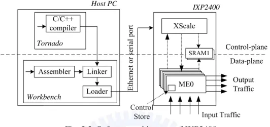
Figure 2.2 elaborates the development environment. The IXP2400 programming can be divided into the XScale programming and the microengine programming. While XScale programs are written in C/C++ under Tornado, microengine programs are written in assembly under Workbench for low-level packet processing capability. The compiled XScale executable is linked with object microcode compiled by the assembler, and loaded into the IXP2400 SRAM from which XScale initializes and loads microcode into the Control Store of microengines. The linked program can also be executed by the Transactor for pure software simulation. Besides, the XScale is little-endian and byte-addressable
while microengines are little-endian but longword-addressable.
2.2.3
Performance Benchmark
Figure 2.3 illustrates the external benchmark environments, for packet forwarding and IPsec. We use SmartBits, which is a networking traffic generator and a performance analyzer, to generate the input traffic and collect and analyze the performance results. For internal tests, some system utilities, such as vmstat, top and GProf, are employed to obtain the system state and other internal behaviors such as CPU utilization and memory usage.
Fig. 2.3. Benchmark environments for (a) packet forwarding and (b) IPsec. We also conduct a number of internal benchmarks, namely board-level simulations using the Transactor within the Workbench, in order to have detailed observations on the hardware utilizations.
Fig. 2.2. Software architecture of IXP2400.
XScale ME0 Input Traffic Tornado Linker C/C++ compiler Assembler Loader Workbench Control-plane Data-plane IXP2400 Host PC Et he rne t o r se ri al por t Output Traffic Control Store SRAM SRAM1
2.2
Mathematical Modeling and Simulation
Real implementations reveal precise observations for specific software/hardware combinations; however, they can hardly reflect generalized implications because of the difficulty in adapting architectural parameters. To remedy this shortcoming, we incorporate mathematical modeling as well as simulations. The former has the best flexibility and efficiency in altering parameters; nonetheless, it often suffers from the problem of state-space explosion. Though being less flexible and efficient than the mathematical modeling, the latter captures well the behaviors of a certain system.
Since our goal is to consider I processors, each of which contains J threads, and then capture the behaviors of processors, threads and memory, we use the Continuous Time Markov chain to mimic a multithreaded multiprocessor network processor. Figure 2.4 exemplifies the transition diagram of a thread. In this example, a thread could be idle, active in processing, accessing memory, ready if not permitted to run, and finished if the packet processing is completed. Based on this concept we can have further extension to support the modeling of multithreaded multiprocessor architecture.
λ j
r
idle (0) active (1) h m finished (4) λ mem (2) ready (3) 1 j u h m 2 j u 3 j u 4 j u λ jr
idle (0) active (1) h m finished (4) λ mem (2) ready (3) 1 j u h m 2 j u 3 j u 4 j uFig. 2.4. Transition diagram of a thread in a multithreaded multiprocessor environment.
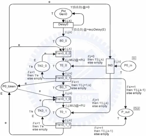
As for the simulation, we adopt the CPN Tools [RWL+03] to employee the timed and colored Petri nets [Mur89] that capture well component-level activities.
The features it supports, including the colored tokens, stochastic functions and hierarchical editing, provide efficiency in the construction of timed, colored Petri nets corresponding to both coprocessors-centric and core-centric models. Figure 2.5 shows an example Petri net describing a multithreaded processor.
Chapter 3
Resource Allocation of the
Coprocessors-centric Network
Processors for Memory Access Intensive
Applications
3.1
Introduction
Networking applications offering extra security and content-aware processing features demand much powerful hardware platforms to achieve high performance. For memory-access intensive applications such as the Network Intrusion Detection Systems (NIDSs) [Roe], general purpose processors with high speed memory banks are often adopted; however, the cost is considerable while the throughput is not satisfactory for that the processors’ utilization is low because of the heavy memory-access overhead. Rather, the Application-Specific Integrated Circuits (ASICs) [JS97] can meet the performance requirement with a circuitry designed for strict guarantees on memory-access latency using pipelined architecture and embedded memory. Nonetheless, the lack of flexibility and long development cycle make it less appealing.
In this work, we implemented a memory-access intensive application, NIDS, over the Intel IXP2400 [INT] whose architecture is similar to most network processors, evaluated the effect of different resource allocations, and finally investigated the allocation measures. Two signature matching algorithms, the Aho-Corasick and Wu-Manber [WM94], were incorporated for their popularity in
many security-related implementations, for example, Snort. Several software components referred to as processing stages [ARB02] were characterized, in which a tentative processor/thread allocation was applied. After implementation, we then conducted both external and internal benchmarks. The former unveiled the throughput of the implementation while the latter analyzed the utilizations of the hardware components for observing potential bottlenecks. According to the benchmark result, the effect of the ME/thread allocation is reviewed and methodologies for the optimal revision of the allocation were subsequently proposed. Finally, since extra memory banks are often exploited to shorten the memory access latency, the feasibility and effectiveness of adopting multiple banks for string-matching applications are discussed.
3.2
Hardware Platform (IXP2400)
As depicted in Fig. 3.1, the IXP2400 consists of several components that are categorized as following.
Multithreaded multiprocessor architecture
The IXP2400 features nine programmable processors: one Intel XScale core [INT] Fig. 3.1. Hardware architecture of IXP2400.
and eight microengines (MEs), operating at 600MHz. The Intel XScale core is responsible for housekeeping functions such as table initialization and exception handling for control-plane packets such as ICMP unreachable packets. Data-plane processing, which accounts for the most part in packet processing, is implemented on MEs. Every ME has eight hardware threads, each of which having its own register set and program counter to support fast context switch when memory accesses occur.
Hierarchical memory structure
To ease the memory-access overhead, IXP2400 exploits four types of memories, DRAM, SRAM, scratchpad, and local memory in an ME, given tradeoffs between size and latency. IXP2400 has one channel of DDR running at 150MHz. The channel can support up to 2GB of DRAM, yielding enough capacity for storing packets. Two channels of Quad Data Rate (QDR) SRAM running at 200MHz are also provided, and up to 16MB can be populated on each channel. The SRAM is primary for accommodating packet descriptors for locating packets in DRAM, queue descriptors, and other data structures frequently used. The on-chip 16KB scratchpad memory operates in the form of rings and provides similar capability to SRAM, while the 2560-words local memory is frequently used as a cache for smaller data structures.
Flexible external interface
The Media Switch Fabric (MSF) is an external interface used to connect the Intel IXP2400 to a physical layer device and/or a switch fabric. The MSF consists of receiving and transmitting interfaces which can be configured for different protocols such as POS PHY Level 3 [POS] and CSIX-L1 [CSI]. Incoming packets are received into the Receive Buffer (RBUF) and outgoing packets are held in the Transmit Buffer (TBUF), which are both 8KB in size. The MEs can move data from RBUF to DRAM and from DRAM to TBUF using the DRAM[rbuf_rd] and
DRAM[tbuf_wr] instructions directly, greatly avoiding packet duplications and unnecessary memory accesses.
Coprocessors
Two kinds of hardware coprocessors, including a hash unit shared by all MEs and a Cyclic Redundancy Code (CRC) unit inside each ME, are incorporated in the system. The hash unit is capable of 48-bit, 64-bit and 128-bit polynomial divisions. A high quality hash alleviates the probability of hash collisions, contributing to fewer memory accesses; however, performing a high-quality hash in software, which occurs frequently in packet classification, is cycle-consuming, and thus should be offloaded to the coprocessor. Similarly, the CRC unit is used to offloading the CRC computation.
Detailed Packet Flow in IXP2400
The processing flow of an ordinary packet is elaborated below referring to Fig. 3.1. Upon the arrival of a packet at the MSF of IXP2400, the MSF partitions the packet into several smaller chunks called mpackets, which can be configured to 64, 128, and 256 bytes in size, and places them into the RBUF elements. The threads of the MEs dedicated for packet receiving in turn perform the reassembly of mpackets, and move them directly from the RBUF into DRAM, in which MEs and the Intel XScale core carry out further operations. The packet processing typically consists of packet classification followed by packet modification. During packet processing at MEs, chances are that some exception handling and housekeeping are manipulated by the Intel XScale core through the interrupt and message queue mechanism. In the later scenario of packet flow, the transmission process is just the reverse of the reception process, namely the packet is segmented into several mpackets by the threads dedicated for packet transmission, and then placed into the TBUF.
3.3
Problem Statements
In addition to the implementation and evaluation of an NIDS, this work focuses on the impact of the processor, thread and memory bank allocations. Some problem statements are discussed below.
Task Allocation and Bottleneck Observation
Before implementing an NIDS, some functional blocks referred to as processing stages need to be identified and then mapped to the platform. During the mapping process, we try to exploit the hardware features such as the hierarchical memory structure and the multithreaded multiprocessor architecture. This involves mainly the assignment of memories to store different data structures, as well as the allocation of threads and MEs. After the system is implemented, we will try to identify possible bottlenecks through the internal and external benchmarks.
Effect of Improper ME/Thread Allocations
The performance of an application is affected by two factors, the computing power and the memory-access latency. The former is determined by the number of processors used referred to as I, while the latter can be alleviated by adjusting the total number of threads employed, namely I×J[LLP02], where J represents number of threads per processor. Observing that the number of processors is fixed to the hardware platform, it is interesting to see how an allocation (I, J), especially an improper one, affects the system performance.
Optimal I and J
It is known that memory-access intensive applications benefit directly from increasing the total number of threads, namelyI×J, rather than individual I and J, because of its ability of hiding memory-access latency. Nonetheless, how to determine a fitting I×J, given a certain hardware spec such as clock rate and
memory service rate, remains unanswered. In addition, we are also interested in finding an optimal (I, J) combination, regardless of the limit on the numbers of MEs and threads per ME of the platform. A (I, J) is considered optimal when the utilizations of both ME and memory are cost-effectively high, as will be explained in section 3.5.
Effectiveness of Employing Multiple Memory Banks
Multiple memory banks reduce the average memory access latency. For memory-access intensive applications, more memory banks are supposed to improve the performance. Nonetheless, the effectiveness could be influenced by whether the accesses are evenly distributed into memory banks. Some experiments are therefore designed to investigate the effectiveness of adding memory banks.
3.4
Design and Implementation
In this section, we introduce basic operations of an NIDS, characterize the operations into processing stages, and finally implement the NIDS by associating the MEs and threads to the stages. Some design issues are discussed to ensure proper inspections.
3.4.1
NIDS Briefing
The processing of an NIDS, for example, Snort [Roe], mainly consists of three phases (1) the packet decoding phase which sets up pointers to packet data at different layers and stores them into data structures for later analysis by the detection engine; (2) the detecting phase, in which a group of rules matched against a packet header are applied for further signature matching, and (3) the alert phase, in which some alert or logging routines are carried out. Although later versions of Snort include the preprocessing phase performing the IP
de-fragmentation and TCP stream reassembly, it is optional andthus excluded in the implementation for simplicity.
3.4.2
Design Issues
According to the above-mentioned characteristic of an NIDS, it is clear that we can implement an NIDS over the IXP2400 by dividing the packet processing into a series of stages, namely the receiver, packet inspector and transmitter, and mapping them onto the MEs. The preprocessing phase is excluded in the mapping since oftentimes it is not done in the fast path [NSH02], but by the XScale.
Moreover, packets can be distributed to a pool of MEs, and thus threads, in the packet inspector to exploit high parallelism. Nevertheless, two problems including
packet ordering and flow interleaving arise.
Packet ordering
The issue of packet ordering occurs in a processing stage when multiple threads are dispatched to process the packets of a flow simultaneously. Oftentimes the amount of time to process a packet is not constant due to context switching, and thus the packet ordering may not be guaranteed, as shown in Fig. 3.2(a). To tackle this problem, a mechanism called ordered threads [JK03], is adopted requiring that threads handle packets in order in a processing stage of several functions, as presented in Fig. 3.2(b). For example, thread 1 is allowed to execute function 1 for a packet only after thread 0 completes the same function for another packet.When thread 0 completes function 1, it notifies thread 1 using inter-thread signaling. However, the effectiveness of multithreading could be greatly degraded if the function contains much memory accesses. The executing thread may not be able to context switch to other threads when performing memory accesses.
Flow interleaving
In packet inspection, a pattern may stretch across multiple packets. If flows are interleaved, it is not guaranteed that two consecutively processed packets belong to the same flow, meaning that patterns across multiple packets can not be inspected appropriately.
To fix these two problems, we refine our design by adding two processing stages, the flow classifier and thread dispatcher, supporting packet ordering. The main idea behind is to classify packets into different flow queues associated with a corresponding flow context, such that flows are no longer interleaved. The flow context comprises the SRAM address of the flow queue keeping the packet descriptors, state of inspection and some status flags. Further, each thread in the packet inspector stage is dispatched by the dispatcher to serve one flow queue. After finishing the inspection of a packet, the packet inspector thread stores the final state of the inspection for later reference by another thread serving the same queue. The implementation of the thread dispatcher will be detailed later in section 3.4.4.
3.4.3
Mapping Processing Stages to the Hardware Platform
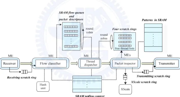
Fig. 3.3 shows the processing stages of an NIDS, as well as the task and resource allocation for IXP2400. The NIDS processing is elaborated as follows. Upon
Fig. 3.2. Timeline showing two consecutive packets (a) being out of order, and (b) being ordered in a processing stage.
fun 1 fun 1 fun 2 fun 2 Thread 0 Thread 1 Time inter-thread signaling inter-thread signaling waiting for a signal waiting for a signal (a) (b)
receiving a packet from an input port, the packet data is moved from RBUF to DRAM; the corresponding packet descriptor is stored in SRAM while a duplicate is passed to the next stage through the receiving scratch ring. Subsequent the flow classifier retrieves a packet descriptor for flow classification which operates as following. First, the IP and port pairs in the packet are used to calculate a hash key for indexing in the hash table in SRAM in order to verify whether the flow which the packet belongs to exists. Since the task requires much computing power, the hash unit is adopted to offload the overhead. If a hash hit occurs, the hash entry pointing to a flow context in SRAM is referred to enqueue the packet descriptor for inspection; otherwise an entry for the new flow is created in the hash table.
The dispatcher thread then round-robinly chooses a flow queue and dispatch an inspector thread to handle the first packet in the queue. Once a packet payload is matched against a pattern, a message is delivered to the XScale through the XScale scratch ring to signal an alert. Finally, the transmitter thread examines the transmitting scratch ring to determine whether a packet is waiting to be sent. If yes, it fetches the packet descriptor in SRAM and sends the entire packet in
DRAM to TBUF for output.
In our implementation, a tentative allocation of MEs and threads is determined based on the processing stages and the benchmark result of Snort, which argues that at least 31% of total processing time is consumed by the detecting phase [FV02]. So, each processing stage is allocated one ME except the packet inspector, which is given four MEs. That gives us totally four MEs, namely thirty-two threads for later adjustment and analysis. For thread allocation in the receiver, eight threads are evenly divided into four groups corresponding to four gigabit ports. Each port is served by two ordered threads to keep packets in order. As for the transmitter, eight ordered threads are assigned to one gigabit port. We adopt eight ordered threads in both classifier and dispatcher stages for the following two reasons leading to out-of-order packets: (1) classifying packets could take vastly different amount of time due to hash collisions, and (2) serving flow queues round-robinly needs that the round-robin counter be accessed by one thread at a time. In the packet inspector, it is manipulated that a flow queue is served by a thread at ay instance, in which ordinary thread scheduling mechanism,, rather than the ordered thread, is employed for better benefit from multithreading. Since a flow queue is served by one thread at a time, packets of a flow will never get out of order. Interaction between the thread dispatcher and packet inspector will be detailed in section 3.4.4.
3.4.4
Algorithms Adopted and Packet Inspection
3.4.4.1
String Matching Algorithms
Packet inspection is a critical stage that influences the performance of an NIDS. Several string matching algorithms were proposed for improvement. However, coding microcode is difficult, since it depends heavily on the hardware characteristics. Two popular algorithms, Aho-Corasick referred to as A-C and Wu-Manber referred to as W-M, are thus used because they are easy to implement
and popular in many applications such as Snort. The two algorithms consist of two common phases: a pre-processing phase, which computes and builds necessary data structures in memory from the input patterns, and an inspection phase, in which patterns are looked up against the packet payload. Nevertheless, the pre-processing phase is time-consuming and typically done by the XSacle. In our implementation, we store the data structures in SRAM for fast retrieval. Since the operation of the A-C involves state transitions, we record the final state immediately after the processing of a packet for later inspection of the succeeding packet in the same flow queue. Similarly, we keep the shift value for the W-M so that patterns across multiple packets can be inspected.
3.4.4.2
Thread Dispatcher and Packet Inspector
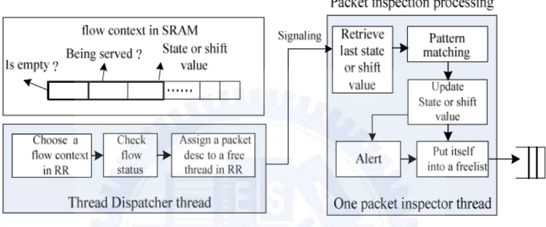
Fig. 3.4 details the interactions between thread dispatcher and packet inspector. As mentioned in section 3.4.3, a flow queue is round-robinly selected and the first packet descriptor in that flow is passed to an inspector thread chosen from the free thread list of the ME. This process involves some operations. First, two flags,
isEmpty and beingServed, of a flow context are checked in each round. The
former indicates if the corresponding flow is empty while the latter denotes whether that flow is being served by a thread. If the flow is not empty and not being served, a packet descriptor is assigned to an inspector thread followed by the corresponding modifications of the two flags. This ensures that a flow is served by only one inspector thread at a time, by which preventing the state (for the A-C) or shift value (for the W-M) from being altered by other threads. The inspector thread then examines a packet payload against the patterns in SRAM and updates accordingly the state or shift value in the flow context. If no pattern is matched, the packet is passed to the transmitter thread to be sent out; otherwise the XScale is notified of a match. Finally, the packet inspector thread puts itself into the free thread list, waiting for the next signal from the dispatcher. The four free thread lists implemented using four scratch rings correspond to the four MEs.
The inspector threads are dispatched round-robinly among the MEs for better load balancing. To avoid the system resource being exhausted by excess idle flows, a timeout counter maintained by the XSacle is associated with each flow. Once the counter turns to zero, the flow queue as well as the flow context and hash entry are removed.
3.5
System Benchmark and Bottleneck Analysis
In this section, we evaluate the performance by externally and internally benchmarking the system implemented using two string matching algorithms.To have both MEs and memory, namely SRAM, well utilized, we investigate the appropriate numbers of I and J for the application. Since the memory access overhead accounts for a considerable portion in the packet processing, the feasibility of exploiting multiple memory banks for load balance is exploited.
3.5.1
Benchmark Setup
The XScale core in our design is responsible simply for the preprocessing and alerting; therefore, in this section we focus mainly on the performance of the MEs which are the main component that handles the most part of packet processing.
Since the performance statistics including the ME and memory utilizations can only be obtained by the simulator, we evaluate the performance through simulations. The preprocessing phase originally done by the XScale is shifted to the receiver ME since the simulator does not comprise the XScale. Notably two MEs from two processing stages, the flow classifier and thread dispatcher, respectively, are borrowed in the analysis due to the dearth of MEs.
3.5.1.1
Patterns for Packet Inspection
Observing that 2475 patterns are used in the current Snort, we employ 2000 random patterns in which characters are generated uniformly according to the guidelines discovered in [AAP04]. The shortest pattern length, LSP, which is known as a major factor on the performance of string matching algorithms such as W-M, is set to four [LHC04].
3.5.1.2
Simulator Setup
The IXP2400 Developer Workbench simulator provides tools for compiling the microC into microcode and a simulator called Transactor, for evaluating the performance. The simulator allows users to configure parameters. In our experiment, the clock of the ME is 600 MHz. The input interface of the MSF is divided into four gigabit ports, while the output interface is a four-gigabit one. The transmitter and receiver buffers are both 256 bytes. Four data streams of 64-byte TCP/IP packets with randomly generated payload are injected. All simulations last for 50000 packets.
3.5.2
Effect of Improper ME/Thread Allocations
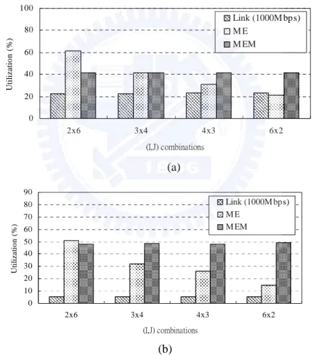
To investigate the effect of improper ME/thread allocations, we compare the performance, in terms of utilization, of the A-C for different (I,J) combinations. As shown in Fig. 3.5(a), I and J can be configured while the total number of
threads,I×J, is fixed to 12. Some observations are made. First, the throughput is influenced mostly byI×J, rather than I, as the throughput remains unchanged for the (I,J) combinations. Second, the average ME utilization degrades while increasing I. This is because the same traffic load is balanced by more MEs. The same explanation applies to the results of the W-M in Fig. 3.5(b). Third, the throughput of the W-M is only one-fourth of the one of A-C. This is due to the relatively high processing overhead of the W-M, as clarified in Fig. 6.
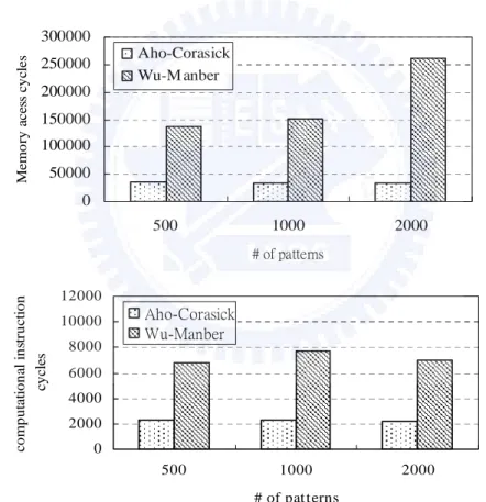
Figure 3.6 profiles the total memory-access cycles referred to as P, as well as Fig. 3.5. Performance of the (a) A-C and (b) W-M for different (I,J) combinations. Total number of threads is fixed at 12.
0 10 20 30 40 50 60 70 80 90 2x6 3x4 4x3 6x2 (I,J) combinations Ut il iza tio n ( % ) Link (1000M bps) M E M EM (a 0 20 40 60 80 100 2x6 3x4 4x3 6x2 (I,J) combinations U til iz a tio n ( % ) Link (1000M bps) M E M EM (a) (b)
the computational cycles referred to as M, required by the A-C and W-M for handling a 64-byte packet. From the figure we can see that the sum of P and M of the W-M is approximately 4 times of the one of A-C. This explains the relative low throughput of the W-M compared with the A-C. Further, the memory access overhead dominates the processing time of a packet, namely 94% for A-C and 98% for W-M. Fortunately this un-balance situation is tolerated by multithreading, which makes the utilizations of MEs and memory much closer to each other than what otherwise will be.
3.5.3
Estimating the Optimal (I,J) Pair
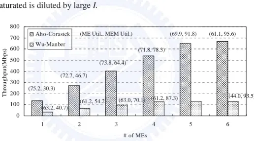
Figure 3.7 depicts the performance of the two implementations by increasing
0 50000 100000 150000 200000 250000 300000 500 1000 2000 # of patterns Mem o ry ac es s cy cles Aho-Corasick Wu-M anber
Fig. 3.6. Profiling of the total (a) memory access cycles and (b) computational cycles for processing a 64-byte packet.
0 2000 4000 6000 8000 10000 12000 500 1000 2000 # of pat terns c o m p u ta tio n al in str u c tio n cy cl es Aho-Corasick Wu-Manber
number of MEs and therefore the total number of threads. Some observations can be made. First, the throughput of A-C is better due to less computational and memory-access overhead. Second, for number of MEs being from one to four, the ME utilizations of both implementations are almost the same, implying that the number of threads per ME is insufficient. Third, initially, the throughputs of both implementations increase with a direct ratio toI× . Nevertheless, the throughput J
increases slightly as I = 5 for W-M and I = 6 for A-C, respectively, because memory is almost fully utilized. Fourth, as I increases and memory utilization approaches 90%, the average ME utilization degrades, because the load making memory saturated is diluted by large I.
We can also estimate a combination of (I,J) such that both ME and memory are best utilized. As we learn from Fig. 3.7, when memory utilization is above 90%, increasing I, and therefore total number of threads contributes slightly to the performance and is not cost-effective. For example, the improvement of memory utilization from incorporating the sixth processor is about 95.6−91.8≈3.8%and
% 6 . 1 9 . 91 5 .
93 − ≈ for A-C and W-M, respectively. Hence, 5×8=40 threads should
be cost-effectively enough for both algorithms to well utilize the memory. Nonetheless, the ME utilization is low when I = 5, meaning that the computing
0 100 200 300 400 500 600 700 800 1 2 3 4 5 6 # of MEs T hr o ughp ut (M bps ) Aho-Corasick Wu-Manber (61.1, 95.6) (44.0, 93.5) (69.9, 91.8) (61.2, 87.3) (71.8, 78.3) (63.0, 70.1) (73.8, 64.4) (61.2, 54.2) (72.7, 46.7) (63.2, 40.7) (75.2, 30.3)
(ME Util., MEM Util.)
Fig. 3.7. The performance of A-C and W-M with different numbers of MEs (eight threads per ME).
power is unnecessarily much and should be further reduced. We fix this problem by employing four MEs, rather than five, so that the average utilization of MEs shall become 87.4% 4 5 % 9 . 69 ≅ × (since % 100 % 5 . 116 3 5 % 9 . 69 > ≅
× ), and J can thus be
estimated to 10 4
40 = . Similarly, a combination of (3,13) can be derived for the
W-M.
3.5.4
Effectiveness of Multiple Memory Banks
One of the solutions to the memory bottleneck is to add more memory banks. To evaluate the benefit, we adopt two SRAM banks to store the data structures of the string matching algorithms. Table 3.1(a) shows that only minor improvement can be gained due to the difficulty of splitting the data structure, namely goto table, of A-C evenly into different memory banks. The W-M, on the contrary, benefits substantially (about 43.7%) from two banks as presented in Table 3.1(b). This is credited to the use of several tables which make the distribution of data a lot easier and more efficient to memory banks.
Table. 3.1. Performance of (a) A-C and (b) W-M with one and two memory banks, respectively. (I,J) = (6,8).
(a)
One memory bank Two memory banks
Avg. ME util. (%) 61.1 63.2
MEM util. (%) 95.6 95.2/1.8
Throughput (Mbps) 670.6 674.4
(b)
One memory bank Two memory banks
Avg. ME util. (%) 44.0 63.2
MEM util. (%) 93.5 70.0/57.2
3.6
Summary
In this work, we elaborate the implementation of a memory-access intensive application, NIDS, over the IXP2400 network processor. We introduce the hardware platform, briefing the NIDS processing flow, and identify necessary processing stages to be mapped to the platform. Among those processing stages, the packet inspection is implemented with the Aho-Corasick and the Wu-Manber algorithm. Some design issues including packet ordering and flow interleaving, which may cause incorrect inspection results for patterns across multiple packets, are discussed and solved. After implementation, we externally and internally benchmark the system aiming to observe the effect of the allocations of processors, threads, and memory banks, as well as possible bottlenecks.
The benchmark result shows that the system can support up to 670 Mbps when implemented using the Aho-Corasick and 133Mbps using the Wu-Manber. It is also observed that given a certain application and algorithm, the throughput is influenced mostly by the total number of threads as long as the ME utilizations do not exceed 100%. Although enlarging the total number of threads by adding more processors benefits the throughput, the ME utilization suffers. This is because the load saturating memory is diluted by the increased I, meaning that J instead should be extended.
The bottleneck is then found to be the SRAM as the I×J exceeds the upperbound k that cost-effectively utilizes the memory. With the upper-bound, we can estimate an optimal (I, J) combination, i.e. (4, 10) for the Aho-Corasic and (3, 13) for the Wu-Manber, respectively. In fact, supposed an application, algorithm and k, an optimal (I, J) can always be derived. Two workarounds are suggested to solve the SRAM bottleneck, namely when I×J>k. The first is to use multiple memory banks. Our result indicates that the performance gains a 43.7% improvement from two banks for Wu-Manber since the data structure itself makes it easy to be evenly distributed among banks. The other is to adopt a multi-port
memory which allows multiple simultaneous memory accesses. This is helpful especially to algorithms, such as the Aho-Corasick, having data structures difficult to be uniformly split.
Two issues are to be investigated in the future. First, real traffic, rather than the synthetic one, should be adopted. The second is to investigate the allocation measures for computational-intensive applications.
Chapter 4
Coprocessors-centric Network
Processors: Analysis, Simulation, and
Design Implications
4.1
Introduction
In this work, we aim to unveil possible hints, especially the thread allocation, for future NP design in two directions: (1) develop a preliminary analytical model using the Continuous Time Markov Chain, and (2) build a Petri net simulation environment which is also used for model validation. Our approach considered both memory and ready queuing effects that are often ignored in other works, and involves two important networking applications, Simple Forwarding and DiffServ, which have different computational and memory access requirements. We propose a concept named P-M ratio and discover that a large I , or J, is needed for high, or low, P-M ratio, and further that when processor overhead (P) is similar to the memory’s (M), the most appropriate number of threads is shown to be 5. Notably the core processor was not included in our model since the control-plane processing accounts for only a minor portion in the packet processing.
Another concern in our approach is the selection of a thread allocation scheme. Thread allocation schemes decide how threads in a processor are arranged for processing packets; adopting an improper scheme could result in un-balanced load distribution among processors. We compared and discussed four possible allocation schemes, and chose the most appropriate one as the base assumption throughout this work. Factors influencing the selection include the amount of
hardware resources, design complexity, and flexibility in processing.
The rest of this article is organized as follows. Section 4.2 introduces the concept of thread allocation schemes. Section 4.3 elaborates the analytical model. Section 4.4 details the construction of the Petri net simulation environment, validates our analytical model, and presents some interesting simulation results. Conclusive remarks and future work are given and discussed in section 4.5.
4.2
Effect of Different Thread Allocation
Schemes
Thread allocations should be carefully involved and studied before analyzing the M-M architecture. Four thread allocation schemes are common in real implementations, in which at most one thread is active in a processor. The first is that a thread is assigned to process a complete packet. Nonetheless, this scheme may require intricate inter-thread communications in order to maintain the packet ordering in a flow.
Another two schemes, which are shown in Fig. 4.1, are called homogeneous and heterogeneous thread allocations, respectively. In the homogeneous allocation, all threads in a processor belong to the same type, e.g., receiver, scheduler, transmitter, etc. Each thread in a processor deals with only part of the packet processing and after that, it signals a certain thread in the succeeding processor for further processing. A thread in a processor may have either fixed or dynamic task assignment, namely it may stick to a certain input port or it may support other ports whenever necessary. Notably, since all threads in a processor are of the same type, this scheme has a more relaxed requirement for the size of the instruction memory while exhibiting desirable data locality in cache. Nonetheless, in the homogeneous scheme, processing load can hardly be distributed to processors evenly, and packet ordering is unlikely to be maintained.
Fig. 4.1. Homogeneous and heterogeneous thread allocations. At most one thread is active per processor.
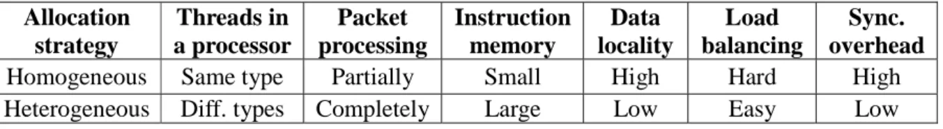
This situation can be avoided with the heterogeneous allocation, where the traffic can be assigned to a processor with a lighter load by some load-balancing hardware and mechanisms [BDE01]. In this scheme, each thread in a processor belongs to different types and is supposed to take charge of an equal overhead in the packet processing. The requirement for a larger instruction memory will not be a problem because less than 5K of it is needed by general header processing applications [RW03], and that requirement has already been supported in many commercial products such as the Intel IXP2400 and Motorola C-5 [MOT]. Another edge of the scheme is the minor synchronization overhead, since the inter-thread communication is done using global registers in the processor. A comparison between these two strategies is shown in Table 4.1. For the reasons discussed above, we take the heterogeneous allocation as the basic assumption in our model throughout this work.
Table 4.1. Comparison between the homogeneous and heterogeneous schemes. Allocation strategy Threads in a processor Packet processing Instruction memory Data locality Load balancing Sync. overhead Homogeneous Same type Partially Small High Hard High Heterogeneous Diff. types Completely Large Low Easy Low
R: S: T:
It is also possible to use the hybrid allocation scheme, in which processors of homogeneous or heterogeneous allocations are incorporated. This scheme preserves the strength of large instruction memory and high data locality, which can be achieved by assigning homogeneous processors to tasks exhibiting high data locality. However, the load balancing and packet ordering originally supported by the heterogeneous scheme no longer exist.
4.3
Overview of the Analytical Model
In this section we present an approximate analysis of the multithreaded multiprocessor network processor using a Continuous Time Markov chain. We define the state space of the model, derive the transition rates and solve the model. In addition to the heterogeneous allocation determined in the previous section, we proceed with the assumption of blocking processing, as shown in Fig. 4.2. The blocking processing contrasts with the non-blocking processing, which is also shown in Fig. 4.2 in that no buffer exists between two adjacent threads of a processor. That is, a thread cannot pass the processing result to its successor and accept another packet if the successor is busy with a packet. Since normally the packet processing overhead, including computation and memory access, is fairly distributed among threads, this simplified assumption has limited influence on the correctness of the model while considerably reducing the state space.
Fig. 4.2. The blocking and non-blocking packet processing schemes. A thread T t accesses memory with rate r during the processing. t
4.4
Markov Chain Formalization
4.4.1
State Definition and State Space Determination
Our model considers I processors, each of which contains J threads, and aims to characterize the behaviors of processors, threads and memory. To do that, we need to clarify possible activities, i.e. statuses transitions, of a thread. They are depicted in Fig. 4.3 and elaborated below. When a packet arrives at an idle thread, the thread either enters the ready queue of the processor waiting for execution, or enters the active status if no thread is currently active. Sometimes it issues a
memory access to, for instance, perform table lookups and manipulate packet
descriptors. Once serviced it re-enters the ready queue, or goes directly back to execution if the ready queue is empty. Normally, the thread becomes idle again after the packet is processed and passed to the succeeding thread. Nonetheless, it may get stuck and enter the finished status if the succeeding thread also has a packet under processing.
Fig. 4.3. Status transitions of a thread.
According to the above descriptions we can formally define a state of the system as J j I i s s s S =( 0,0... 0,j... i,j), 0≤ < and0≤ < , where }si,j∈{0:idle,1:active,2:mem,3:ready,4: finished represents the status of Ti,j , the jth thread in processor i. Furthermore we define
} |
{ )
(k s, s, k
S = i j ij = , so that the number of executing processors and number of accesses in the memory system equal to | S(1)| and | S(2)|, respectively. We also define h(i)={si,j |si,j =2} so that the number of queued memory accesses of processor i is denoted by |h(i)|. Besides, the RSS (Random Selection for Service), rather than the FIFO, is assumed as the queuing discipline for both memory and ready queues. This assumption further diminishes the state space by disregarding the ordering information in the queues, and is proven not to affect the correctness of the analytical result in section 4.5. Taking (I,J)=(2,2) as an example, the state space can be derived by excluding exceptional states exhibiting the following properties:
1. A processor has more than one active thread. For instance, 1,1,0,0)( .
2. At least one ready thread but no active thread, such as 2,3,0,0)( . One of the ready threads must enter the active status as long as the previous active thread completes its processing.
immediately to the succeeding one. 4. si,J−1 =4; the same reason as the one in 3.
4.4.2
Determination of the Status Transition Diagram and
State Transition Matrix
We will need the state transition matrix in order to solve the model. To derive the matrix, however, we have to deal with the status transition rate diagram of threads since a state change occurs when one or more threads alter its status. By assuming the packet arrival rate for processor i as λi, memory access rate and service time of the jth thread in that processor as ri,j and 1 μi,j , memory service rate as m, and number of queued memory accesses from the processor as h, we can have the status transition rate diagram shown in Fig. 4.4. Notably the service rates, as well as the memory access rates, of threads having same thread index in all processors are set the same because of the homogeneity among those threads. That is,
j j
i μ
μ, = and ri,j =rj.
Notice that some status transitions in Fig. 4.4 do not have a rate because of being a follower transition. A transition is regarded as a follower if it does not initiate a status transition but follow a certain activator transition which actively launches a transition. For example, a finished thread (follower) blocked by its successor can enter the idle status only after the successor (activator) finishes processing and passes down the packet. Another example is that a ready thread (follower) will never enter the active status unless a thread switches out from active.