球形螺旋齒輪之特性研究
166
0
0
全文
(2) 球形螺旋齒輪之特性研究 Characteristic Study of Spherical Helical Gears. 研 究 生:趙立碁. Student:Li-Chi Chao. 指導教授:徐瑞坤 博士. Advisor:Dr. Ray-Quan Hsu. 共同指導教授:蔡忠杓 博士. Co-Advisor:Dr. Chung-Biau Tsay. 國 立 交 通 大 學 機 械 工 程 學 系 博 士 論 文. A Dissertation Submitted to Department of Mechanical Engineering College of Engineering National Chiao Tung University in partial Fulfillment of the Requirements for the Degree of Doctor of Philosophy in Mechanical Engineering. June 2010. Hsinchu, Taiwan, Republic of China. 中 華 民 國 九 十 九 年 六 月.
(3) 球形螺旋齒輪之特性研究 學生:趙立碁. 指導教授:徐瑞坤博士 共同指導教授:蔡忠杓博士 國立交通大學機械工程學系. 摘要 球形齒輪(Spherical gear)是由日本三留謙一教授所提出的一種新型的齒輪。 由其幾何外形來區分,球形齒輪可分為凸狀球形齒輪(Convex spherical gear)與凹 狀球形齒輪(Concave spherical gear)。由球形齒輪所組成之齒輪組共有三種配對型 式:凸狀球形齒輪配凸狀球形齒輪、凸狀球形齒輪配凹狀球形齒輪及凸狀球形齒 輪配正(螺旋)齒輪。與一般常用之正齒輪組不同的是,球形齒輪組(Spherical gear set)具有可容許軸交角變動與軸裝配誤差且不發生齒形干涉之傳動特性。 基於球形齒輪在組裝上的優點,本論文提出一種結合球形齒輪及螺旋齒輪特 性的球形螺旋齒輪(Spherical helical gear)。球形螺旋齒輪除了具有球形齒輪所有 的幾何特色及傳動特性外,亦可透過球形螺旋齒輪之齒輪螺旋角(Helix angle)的 設計,以交錯軸的組裝型式(Crossed axes mounting mode)進行傳動。因此,若能 建立出球形螺旋齒輪的數學模式,則可利用此數學模式來進行球形螺旋齒輪之相 關分析,以提供產業界更進一步了解球形螺旋齒輪之特性及應用上的限制。 由於滾齒加工方法具有切削效率高與成本低的加工特性,因此,本論文選用 滾齒加工方法來模擬創成凸狀及凹狀球形螺旋齒輪,進一步分析並探討由滾齒加 工所創成之球形螺旋齒輪所組成之齒輪組的接觸特性。首先,本論文建立一把 ZN 型蝸桿滾齒刀之齒面數學模式,接著依據滾齒加工之創成機構與齒輪原理推 導出由此 ZN 型蝸桿滾齒刀所創成之凸狀及凹狀球形螺旋齒輪之齒面數學模式, 並利用所建立之凸狀與凹狀球形螺旋齒輪之齒面數學模式進行後續的電腦模. i.
(4) 擬,包括球形齒輪之齒形過切分析(Tooth undercutting analysis)、齒形尖點分析 (Tooth pointing analysis)、齒面接觸分析(Tooth contact analysis)及接觸橢圓(Contact ellipses)分析,最後再利用本論文所發展的球形螺旋齒輪有限元素網格產生軟 體,自動產生一組於接觸狀態的球形螺旋齒輪組之有限元素接觸模型,接著再使 用有限元素商用分析軟體 ABAQUS/Standard 進行球形螺旋齒輪組之應力分析 (Stress analysis)。 齒形過切分析探討在何種齒輪設計參數及滾齒加工參數下,凸狀球形螺旋齒 輪會發生齒形過切的現象及其齒形過切之發生位置,而齒形尖點分析則探討當凹 狀球形齒輪發生齒形尖點時,其所對應的齒輪設計參數及滾齒加工參數,以提供 適合的球形齒輪設計參數及加工參數。齒面接觸分析則探討三種配對型式的球形 螺旋齒輪組,分別在平行軸及交錯軸組裝,且在具有裝配誤差及理想組裝狀況時 之運動誤差、接觸點位置與接觸比。接觸橢圓分析則利用齒面外形法(Surface separation topology method)來探討三種配對型式的球形齒輪組在不同組裝條件下 之接觸橢圓的位置、大小與平均長短軸比。此外,應力分析則模擬球形螺旋齒輪 組在實際受負載情況時,其可能產生之齒面接觸應力及齒根彎曲應力。. ii.
(5) Characteristic Study of Spherical Helical Gears Student: Li-Chi Chao. Advisor: Dr. Ray-Quan Hsu Co-Advisor: Dr. Chung-Biau Tsay Department of Mechanical Engineering National Chiao Tung University. ABSTRACT The spherical gear is a new type of gears proposed by Mitome. Geometrically, the spherical gears have two types of gear teeth-convex tooth and concave tooth. The spherical gear sets have three types of mating combinations: convex tooth with concave tooth, convex tooth with convex tooth and convex tooth with spur gear tooth. Different from that of the conventional spur gear set, the spherical gear set is in point contact and allows variable transmission shaft angles and larger axial misalignments without gear interference during the gear drive meshing. Based on the advantages of the spherical gear, this study proposes a gear by considering the assembly and transmission characteristics of the spherical gear and helical gear, called spherical helical gear. The spherical helical gear has all geometry and transmission characteristics of the spherical gear, while the gear set can also be assembled in crossed axes mounting mode. Therefore, to develop a complete mathematical model of the spherical helical gears with convex and concave teeth can provide further investigation on the manufacturing conditions, transmission characteristics and application limits of the spherical helical gear for industry. In this study, hobbing method is considered for generation of spherical helical gears with convex and concave teeth due to its high cutting efficiency and low iii.
(6) manufacturing cost. Based on the hobbing generation mechanism and theory of gearing, mathematical models of the spherical helical gears with convex and concave teeth can be developed. Firstly, the surface equation of a ZN-type worm-type hob cutter is derived, and then surface equations of the spherical helical gears with convex tooth and concave teeth cut by the hob cutter can be obtained. Sequentially, the tooth undercutting and tooth pointing condition equations for the convex and concave spherical helical gears are derived by utilizing the developed tooth surface equations of the gears, respectively. Therefore, the limit curves of the tooth non-undercutting of the convex spherical helical gear under different design parameters are investigated, while the Z cross-sections of tooth pointing beginning of the concave spherical helical gear are determined. Moreover, the tooth contact analysis (TCA) method is applied to determine the contact characteristics, such as kinematic errors, contact ratios and contact positions, of the spherical helical gear set with the three mating combinations (convex pinion mating with convex gear, convex pinion mating with concave gear and convex pinion mating with helical gear) and two assembly modes (parallel axes and crossing axes modes). Surface separation topology method is adopted to find the contact ellipses and bearing contacts of the spherical helical gear set, and the average ratio a/b of the major and minor axes of contact ellipses of the spherical helical gear set can also be obtained. Finally, an automatic mesh-generation program of the spherical helical gear sets is developed to investigate the stress analysis of the gear sets by utilizing the commercial FEA package, ABAQUS/Standard. Therefore, the contact and bending stress contours of the spherical helical gear sets under two axes mounting modes and three mating combinations can be determined.. iv.
(7) ACKNOWLEDGEMENT(誌謝) 在交通大學機械工程學系博士班五年的學習過程,隨著論文的 付梓,即將劃上句點,回顧這段時間以來的點點滴滴,充滿歡樂, 也 夾 雜 著 些 許 不 捨;歡 樂 的 是 有 這 麼 多 人 填 滿 我 人 生 的 錄 影 帶,不 捨的是即將告別這奮鬥好幾年的戰場,轉往未知的新領域。 本論文能順利完成,幸蒙蔡教授忠杓與徐教授瑞坤的指導與教 誨,對於研究的方向、觀念的啟迪、架構的匡正與求學的態度逐一 斧正與細細關懷,於此獻上最深的敬意與謝意。此外,論文口試期 間,承蒙口試委員顏教授鴻森、宋教授震國、洪教授景華與馮教授 展 華 的 鼓 勵 與 疏 漏 處 之 指 正,使 得 本 論 文 更 臻 完 備,在 此 謹 深 致 謝 忱。 論文寫作期間,承蒙張老師信良、學長威良、怡呈、家彰、瑞 堂、冠宇、政成及煌棊提供寶貴的意見;感謝張小姐鴻瑜、好友明 達、志榮、陽光與正展的關懷與支持;學弟政豪、俊諭、家誠、宗 賢、健 育 與 庚 慶 的 鼎 力 相 助;之 灝 與 之 頤 為 我 這 五 年 的 研 究 生 涯 注 入 很 不 一 樣 的 元 素。對 於 所 有 幫 助 與 關 懷 過 我 的 人,致 上 由 衷 感 謝。 外出休閒的時候,可愛女友與小香菇們的賣力演出更填滿了很 多我的人生底片,感謝你們這十幾年來的相伴,有了你們的電力, 才使得我的博士戰鬥營有持續下去的動力。 另外,可愛女友在背後的默默支持更是我另一個前進的動力, 沒 有 妳 的 體 諒、包 容 及 在 生 活 小 細 節 上 的 提 醒,相 信 這 五 年 的 博 士 生活將是很慌亂的情況。 最後,特將本文獻給我最敬愛的親人,感謝您們無時無刻的關 懷 包 容 與 經 濟 上 的 支 持,讓 我 能 專 注 於 課 業 研 究 中,願 以 此 與 家 人 共享。. Jackicy 謹 誌 於 新 竹 中華民國九十九年六月. v.
(8) TABLE OF CONTENTS 摘要……………………………………………………………………..………….. ABSTRACT……………………………………………………………………….. ACKNOWLEDGEMENT(誌謝)………………………………………………… TABLE OF CONTENTS…………………………………………………………. LIST OF TABLES………………………………………………………………… LIST OF FIGURES……………………………………………………………….. NOMENCLATURE………………………………………………………………. CHAPTER 1 Introduction………………………………………………………... 1.1 Features of spherical gear……………………………………………… 1.2 Literatures review……………………………………………………… 1.3 Motivation……………………………………………………………… 1.4 Overviews……………………………………………………………… CHAPTER 2 Mathematical Model of Spherical Helical Gears………………... 2.1 Introduction…………………………………………………………….. 2.2 Mathematical model of the ZN-type worm-type hob cutter…………… 2.3 Tooth generation of the convex spherical helical gear…………………. 2.3.1 Relationship between hob cutter and convex spherical helical gear………………………………………………………………. 2.3.2 Equation of meshing for convex spherical helical gears………... 2.3.3 Mathematical model of the convex spherical helical gear………. 2.4 Tooth generation of the concave spherical helical gear………………... 2.4.1 Relationship between hob cutter and concave spherical helical gear………………………………………………………………. 2.4.2 Equation of meshing for concave spherical helical gears……….. 2.4.3 Mathematical model of concave spherical helical gear…………. 2.5 Computer graphs of convex and concave spherical helical gears……... 2.6 Transverse pitch chord thicknesses of convex, concave and 2.7. conventional helical gears…………………………………………….... Remarks……………………………………………………………….... CHAPTER 3 Tooth Undercutting and Tooth Pointing Analyses………………. 3.1 Introduction…………………………………………………………….. 3.2 Tooth undercutting of convex spherical helical gear…………………... 3.3 Tooth pointing of concave spherical helical gear……………………… 3.4 Numerical examples…………………………………………………… 3.5 Remarks………………………………………………………………... CHAPTER 4 Tooth Contact Analysis……………………………………………. vi. i iii v vi viii x xiv 1 1 6 8 9 11 11 13 18 18 21 27 27 27 30 36 36 38 39 40 40 42 50 53 62 64.
(9) 4.1 4.2 4.3 4.4 4.5 4.6. Introduction……………………………………………………………. Meshing model for spherical helical gear set………………………….. Kinematic errors……………………………………………………….. Contact ratio……………………………………………………………. Contact ellipses………………………………………………………… Numerical examples…………………………………………………… 4.6.1 Spherical helical gear sets under parallel axes mounting mode…. 4.6.2 Spherical helical gear sets under crossed axes mounting mode…. 4.7 Remarks………………………………………………………………... Chapter 5 Finite Element Stress Analysis……………………………………….. 5.1 Introduction……………………………………………………………. 5.2 Finite element contact models of spherical helical gear sets…………... 5.2.1 Processes of establishing FE contact model…………………….. 5.2.2 Simplified meshing model of a gear set…………………………. 5.2.3 Meshes convergence test and local refined FE model…………... 5.3 Numerical examples…………………………………………………… 5.4 Remarks………………………………………………………………... CHAPTER 6 Conclusions and Future Works…………………………………... 6.1 Conclusions……………………………………………………………. 6.2 Future works…………………………………………………………… REFERENCES…………………………………………………………………….. 64 65 71 73 73 78 78 89 98 101 101 102 102 104 107 111 127 129 129 132 134. APPENDIX A Stress distributions of A Spherical Helical Gear Set with Uniform Element Size along Tooth Thickness Direction………………………………………………………… 140 APPENDIX B Stress Distributions of A Conventional Helical Gear Set with Axial Misalignments under Parallel Axes Mounting Mode……………………………………………………………… 142. vii.
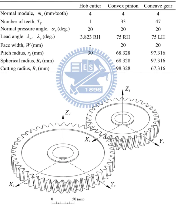
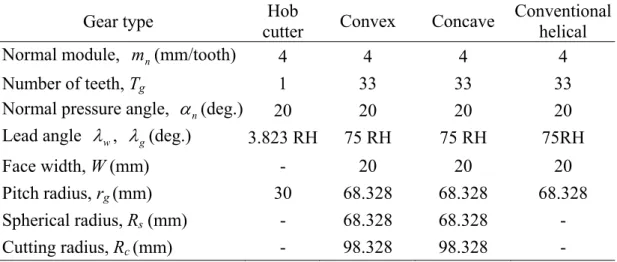
(10) LIST OF TABLES Table 2.1. Table 3.3. Major design parameters of the hob cutter, convex spherical helical pinion and concave spherical helical gear…………………………….. Major design parameters of the hob cutter, convex spherical, concave spherical and conventional helical gears……………………………… Major design parameters of the hob cutter, convex spherical helical gear……………………………………………………………………. The coordinates of left- and right-side tooth profiles of the convex spherical helical gear at Zg=0mm cross-section………………………. The Zg cross-section of tooth pointing beginning of the concave. Table 3.4. spherical helical gear under different normal pressure angle n……… The Zg cross-section of tooth pointing beginning of the concave. Table 2.2 Table 3.1 Table 3.2. Table 4.1 Table 4.2. Table 4.3. Table 4.4 Table 4.5 Table 4.6. Table 5.1. Table 5.2 Table 5.3 Table 5.4. 37 38 54 55 63. spherical helical gear under different gear’s lead angle g……………. 63 Major design parameters of hob cutter, pinion and gear for spherical helical gear sets under parallel axes mounting mode…………………. 80 Contact ratios and rotation angles of the spherical helical gear sets under parallel axes mounting mode and two different assembly conditions……………………………………………………………... 88 Average ratio a/b and rotation angles of major and minor axes of contact ellipses of the spherical helical gear sets under parallel axes mounting mode and two different assembly conditions………………. 88 Major design parameters of hob cutter, pinion and gears for spherical helical gear sets under crossed axes mounting mode…………………. 90 Contact ratios of the spherical helical gear sets with crossed axes under different assembly conditions…………………………………... 98 Average ratio a/b of major and minor axes of contact ellipses of spherical helical gear sets with crossed axes meshing under different assembly conditions…………………………………………………... 98 Major design parameters of spherical helical gear set with convex pinion and concave gear under parallel and crossed axes mounting modes………………………………………………………………….. 104 Mesh densities of the spherical convex pinion and concave gear…….. 108 Major design parameters of the spherical helical gear sets under parallel axes mounting mode………………………………………….. 111 Contact and bending von-Mises stresses of the spherical helical gear set with three types of mating combinations under parallel axes mounting mode at the pinion’s beginning rotation angle……………... 112 viii.
(11) Table 5.5 Table 5.6. Major design parameters of the spherical helical gear sets under crossed axes mounting mode………………………………………….. 120 Contact and bending von-Mises stresses of the spherical helical gear set with three types of mating combinations under crossed axes mounting mode at the pinion’s beginning rotation angle……………... 120. ix.
(12) LIST OF FIGURES Fig. 1.1 Fig. 1.2 Fig. 1.3 Fig. 2.1 Fig. 2.2 Fig. 2.3 Fig. 2.4 Fig. 2.5 Fig. 2.6 Fig. 2.7 Fig. 2.8 Fig. 2.9 Fig. 3.1 Fig. 3.2 Fig. 3.3 Fig. 3.4 Fig. 3.5 Fig. 3.6 Fig. 3.7 Fig. 3.8 Fig. 3.9. Mating statuses of spherical gear sets with axial misalignments……... The changes of straight pitch traces in axial section for different types of gears………………………………………………………………... The changes of quadratic pitch traces in axial section for different types of gears………………………………………………………….. Hobbing locus for spherical helical gear with (a)convex teeth and (b)concave teeth………………………………………………………. Geometric relationships of the straight-edged cutting blade and the ZN-type worm-type hob cutter……………………………………….. Coordinate systems between the cutting blade and ZN-type worm-type hob cutter…………………………………………………. Generating relationship between hob cutter and convex spherical helical gear……………………………………………………………. Coordinate systems between the hob cutter and convex spherical helical gear……………………………………………………………. Generating relationship between hob cutter and concave spherical helical gear……………………………………………………………. Coordinate systems between the hob cutter and concave spherical helical gear……………………………………………………………. Computer graph of the spherical helical gear set with convex pinion and concave gear……………………………………………………… Transverse pitch chord thicknesses of the convex spherical, concave spherical and conventional helical gears……………………………… The phenomenon of tooth undercutting………………………………. The phenomenon of tooth pointing…………………………………… Simulation of a generation mechanism with two-parameter motion…. Tooth pointing of concave spherical helical gear……………………... Tooth profile of the convex spherical helical gear with tooth undercutting under different Zg cross-sections………………………... Locations of limit curves of the convex spherical helical gear under different number of teeth Tg…………………………………………... Locations of limit curves of the convex spherical helical gear under different gear's lead angle g………………………………………….. Locations of limit curves of the convex spherical helical gear under different hob cutter's pitch radius rw…………………………………... Locations of limit curves of the convex spherical helical gear under x. 2 4 5 12 14 16 19 22 29 31 37 39 41 41 46 52 55 56 58 59.
(13) Fig. 3.10 Fig. 4.1 Fig. 4.2 Fig. 4.3 Fig. 4.4 Fig. 4.5 Fig. 4.6 Fig. 4.7. Fig. 4.8. Fig. 4.9. Fig. 4.10. Fig. 4.11. Fig. 4.12. Fig. 4.13. Fig. 4.14. Fig. 4.15. different normal pressure angle n……………………………………. The Zg cross-sections of tooth pointing beginning of the concave spherical helical gear………………………………………………….. Simulation of meshing for spherical helical gear set with assembly errors…………………………………………………………………... Relationship among two contact teeth and their common tangent plane…………………………………………………………………... Mounting relationships of the spherical helical gear set under the crossed axes mounting mode………………………………………….. Coordinate system relationship of the contact point and tangent plane Schematic diagram for surface topology measurement……………… Two axes mounting modes of the spherical helical gear sets………… KEs of the spherical helical gear set with convex pinion and convex gear under parallel axes mounting mode and different assembly conditions……………………………………………………………... Contact ellipses and contact loci on tooth surfaces of the spherical helical gear set under parallel axes mounting mode and different assembly conditions…………………………………………………... KEs of the spherical helical gear set with convex pinion and concave gear under parallel axes mounting mode and different assembly conditions……………………………………………………………... Contact ellipses and contact loci on tooth surfaces of the spherical helical gear set under parallel axes mounting mode and different assembly conditions…………………………………………………... KEs of the gear set with convex pinion and conventional helical gear under parallel axes mounting mode and different assembly conditions……………………………………………………………... Contact ellipses and contact loci on tooth surfaces of the gear set under parallel axes mounting mode and different assembly conditions……………………………………………………………... KEs of the spherical helical gear set with convex pinion and convex gear under crossed axes mounting mode and different assembly conditions……………………………………………………………... Contact ellipses and contact loci on tooth surfaces of the spherical helical gear set under crossed axes mounting mode and different assembly conditions…………………………………………………... KEs of the spherical helical gear set with convex pinion and concave gear under crossed axes mounting mode and different assembly xi. 60 61 66 68 72 75 77 79. 81. 81. 84. 84. 86. 86. 91. 91 93.
(14) Fig. 4.16. Fig. 4.17. Fig. 4.18 Fig. 5.1 Fig. 5.2 Fig. 5.3 Fig. 5.4 Fig. 5.5 Fig. 5.6. Fig. 5.7 Fig. 5.8 Fig. 5.9. Fig. 5.10. Fig. 5.11. Fig. 5.12. Fig. 5.13. conditions……………………………………………………………... Contact ellipses and contact loci on tooth surfaces of the spherical helical gear set under crossed axes mounting mode and different assembly conditions…………………………………………………... KEs of the gear set with convex pinion and conventional helical gear under crossed axes mounting mode and different assembly conditions……………………………………………………………... Contact ellipses and contact loci on tooth surfaces of the gear set under crossed axes mounting mode and different assembly conditions Processes of establishing the FE contact model of a spherical helical gear……………………………………………………………………. Finite element contact model of a spherical helical gear set with convex pinion and concave gear under parallel axes mounting mode... Finite element contact model of a spherical helical gear set with convex pinion and concave gear under crossed axes mounting mode... Simplified contact model of a gear set with boundary conditions……. Finite element model of the convex spherical helical pinion with different mesh densities……………………………………………….. Convergence test of nodal displacements and bending stresses for the mating of spherical convex pinion and concave gear with four teeth subjected to a torque of 200N-m………………………………... Finite element contact model of the spherical helical gear set with local refined meshes under parallel axes mounting mode…………….. Finite element contact model of the spherical helical gear set with local refined meshes under crossed axes mounting mode…………….. von-Mises stress distributions on tooth surfaces of the spherical helical gear set with convex pinion and convex gear under the parallel axes mounting mode and ideal assembly condition…………………... von-Mises stress distributions on tooth surfaces of the spherical helical gear set with convex pinion and concave gear under the parallel axes mounting mode and ideal assembly condition………….. von-Mises stress distributions on tooth surfaces of the spherical helical gear set with convex pinion and conventional helical gear. 93. 96 96 103 105 105 106 108. 109 110 110. 113. 114. under the parallel axes mounting mode and ideal assembly condition.. 115 von-Mises stress distributions on tooth surfaces of the spherical helical gear set with convex pinion and concave gear under the parallel axes mounting mode and axial misalignments……………….. 117 von-Mises stress distributions on tooth surfaces of the spherical xii.
(15) Fig. 5.14. Fig. 5.15. Fig. 5.16. Fig. 5.17. Fig. 5.18. Fig. A.1. Fig. B.1. helical gear set with large modified spherical radii under the parallel axes mounting mode and ideal assembly condition…………………... von-Mises stress distributions on tooth surfaces of the spherical helical gear set with convex pinion and convex gear under crossed axes mounting mode and ideal assembly condition…………………... von-Mises stress distributions on tooth surfaces of the spherical helical gear set with convex pinion and concave gear under crossed axes mounting mode and ideal assembly condition…………………... von-Mises stress distributions on tooth surfaces of the spherical helical gear set with convex pinion and conventional helical gear under crossed axes mounting mode and ideal assembly condition…… von-Mises stress distributions on tooth surfaces of the spherical helical gear set with convex pinion and concave gear under crossed axes mounting mode and ideal assembly condition…………………... von-Mises stress distributions on tooth surfaces of the spherical helical gear set with large modified spherical radii under the parallel axes mounting mode and ideal assembly condition…………………... von-Mises stress distributions on tooth surfaces of the spherical helical gear set with convex pinion and convex gear under the parallel axes mounting mode and ideal assembly condition………………… von-Mises stress distributions on tooth surfaces of the conventional. 119. 121. 122. 123. 124. 126. 141. helical gear set with axial misalignment v 0.15 under the. Fig. B.2. parallel axes mounting mode………………………………………….. 143 von-Mises stress distributions on tooth surfaces of the conventional helical gear set with axial misalignment h 0.1 under the parallel axes mounting mode………………………………………… 144. xiii.
(16) NOMENCLATURE a/b. Ratio of major and minor axes of contact ellipses. bn. Cutting blade width or normal groove width of the ZN-type worm-type hob cutter, as shown in Figs. 2.2(c) and (d). dj. Separation distance measured from common tangent plane to pinion surface (j=1) or gear surface (j=2), as shown in Fig. 4.5(b). dt. Tooth thickness of a tooth topland, as shown in Fig. 3.4. fj. Equations of meshing of the convex spherical gear (j=1, 2). gj. Equations of meshing of the concave spherical gear (j=1, 2). la. Shift distance of the ZN-type worm-type hob cutter along its spindle axis, as shown in Figs. 2.5 and 2.7. lb. Surface parameter of the ZN-type worm-type hob cutter, as shown in Fig. 2.2 (b). lc , j. Shortest distance between hob cutter rotation axis and convex (j=vex) and concave (j=cave) spherical helical gear rotation axes, as shown in Figs. 2.5 and 2.7. lb ,max. Upper bounds of the working interval of the ZN-type worm-type hob cutter. lb ,min. Lower bounds of the working interval of the ZN-type worm-type hob cutter. lx , j. Radial feed displacement of the ZN-type worm-type hob cutter for cutting convex (j=vex) and concave (j=cave) spherical helical gears, as shown in Figs. 2.4(b) and 2.6(b). xiv.
(17) lz , j. Axial feed displacement of the ZN-type worm-type hob cutter for cutting convex (j=vex) and concave (j=cave) spherical helical gears, as shown in Figs. 2.4(b) and 2.6(b). mc. Contact ratio of the spherical helical gear set. mn. Normal module of the spherical helical gear. mwg , j. Gear ratio between number of thread of hob cutter and number of teeth of convex (j=vex) and concave (j=cave) spherical helical gears. pw. Screw parameter of the ZN-type worm-type hob cutter, as shown in Fig. 2.3. pg , j. Screw parameter of the generated convex (j=vex) and concave (j=cave) spherical helical gears. ( r , t ). Polar coordinates for contact ellipse measurement, as shown in Fig. 4.5(a). rf. Root radius of the ZN-type worm-type hob cutter, as shown in Fig. 2.2(c). rg , j. Pitch radius of the convex (j=vex) and concave (j=cave) spherical helical gears, as shown in Figs. 2.4(b) and 2.6(b). ro. Outside radius of the ZN-type worm-type hob cutter, as shown in Fig. 2.2(c). rt. Distance measured from cutting blade tip to the original point Ob of coordinate system Sb of the hob rotation axis, as shown in Fig. 2.2(b). rtl. Radius of tooth top circle, as shown in Fig. 3.4. rw. Pitch radius of the ZN-type worm-type hob cutter, as shown in Fig. 2.2(c). d. Shortest vector measured from the center of the work piece to that of. xv.
(18) the hob cutter, as shown in Figs. 2.5 and 2.7 n (f j ). Unit surface normal vector of pinion (j=1) or gear (j=2) expressed in fixed coordinate system Sf , as shown in Fig. 4.2. C. Operational center distance of spherical helical gear set with center distance error, as shown in Fig. 4.1. Hg,j. Lead of the generated convex (j=vex) and concave (j=cave) spherical helical gears, as shown in Figs. 2.4(a) and 2.6(a). Rc , j. Radius of hobbing locus for convex (j=vex) and concave (j=cave) spherical helical gear generations, as shown in Figs. 2.4(b) and 2.6(b). Rs , j. Spherical radius of convex (j=vex) and concave (j=cave) spherical helical gears, as shown in Figs. 2.4(b) and 2.6(b). Sj. Coordinate systems S j (j=b, c, f, g, h, m, n, p, q, t, v, w, 1, 2). Tg , j. Number of teeth of the convex (j=vex) and concave (j=cave) spherical helical gear. Tj. Number of teeth of pinion (j=1) and gear (j=2). Tw. Thread of the ZN-type worm-type hob cutter. W. Tooth face width of generated gear. L ij. 3×3 homogenous coordinate transformation matrix for vectors transforming from coordinate system S j to Si. M ij. 4×4 homogenous coordinate transformation matrix for position vectors transforming from coordinate system S j to Si. Nj. Surface normal vector expressed in coordinate system Sj (j=w, q). Rb. Position vector of the straight-line cutting blade expressed in its coordinate system Sb xvi.
(19) R (f j ). Position vectors of pinion (j=1) and gear (j=2) expressed in fixed coordinate system Sf , as shown in Fig. 4.2. R (qg , j ). Position vectors of convex (j=vex) and concave (j=cave) spherical helical gears, as shown in Figs. 2.5 and 2.7. ) R (w q. Position vectors of hob cutter express in coordinate system Sq , as shown in Figs. 2.5 and 2.7. R t( j ). Position vectors of pinion (j=1) and gear (j=2), expressed in common tangent plane coordinate system St. Rw. Position vector of the ZN-type worm-type hob cutter expressed in coordinate system Sw. Vq( g , j ). Velocity of generated convex (j=vex) and concave (j=cave) spherical helical gears expressed in coordinate system Sq. Vq(w). Velocity of the ZN-type worm-type hob cutter expressed in coordinate system Sq. Vq(wg ). Relative velocity between the ZN-type worm-type hob cutter and generated gear expressed in coordinate system Sq. Vx. Linear velocity of radial feed motion of the ZN-type worm-type hob cutter, as shown in Figs. 2.4(b) and 2.6(b). Vz. Linear velocity of axial feed motion of the ZN-type worm-type hob cutter, as shown in Figs. 2.4(a) and 2.6(a). n. Half-apex blade angle or normal pressure angle of generated gear, as shown in Fig. 2.2(b). g( j ). Helix angle of pinion (j=1) and gear (j=2), as shown in Fig. 4.3. . Angle measured from axis Zm to axis Zn, as shown in Fig. 4.4. c. Cone angle of conical gear, as shown in Fig. 1.2(b). xvii.
(20) . Angle measured from axis Zn to axis Zt, as shown in Fig. 4.4. 1. Actual rotation angle of pinion, as shown in Fig. 4.1. 1S. Pinion’s rotation angle of spherical helical gear set at the starting contact point during meshing. 2. Actual rotation angle of gear, as shown in Fig. 4.1. 1E. Gear’s rotation angle of spherical helical gear set at the ending contact point during meshing. g , j. Rotational angle of the generated convex (j=vex) and concave (j=cave) spherical helical gear, as shown in Figs. 2.5 and 2.7. w. Surface parameter of the ZN-type worm-type hob cutter, as shown Fig. 2.3(b). g , j. Lead angle of the generated convex (j=vex) and concave (j=cave) spherical helical gears, as shown in Figs. 2.4(a) and 2.6(a). (gj ). Lead angle of pinion (j=1) and gear (j=2), as shown in Fig. 4.3. w. Lead angle of the ZN-type worm-type hob cutter, as shown in Figs. 2.2(a), 2.4(a) and 2.6(a). . Spindle rotation angle of the ZN-type worm-type hob cutter, as shown in Figs. 2.5 and 2.7. . Cross angle between the ZN-type worm-type hob cutter and work piece rotation axes, as shown in Figs. 2.4(a) and 2.6(a). o. Cross angle formed by pinion’ and gear’s rotation axes, as shown in Figs. 4.1 and 4.3. ρ( j). Position vector measured from original point Oq of coordinate system Sq to center of hob cutter (j=w) or work piece (j=g), as shown in Fig. 3.3. xviii.
(21) s, j. Spherical angle of convex (j=vex) and concave (j=cave) spherical helical gears, as shown Figs. 2.4(b) and 2.6(b). g,j. Angular velocity of the generated convex (j=vex) and concave (j=cave) spherical helical gears, as shown in Figs. 2.4 and 2.6. s,j. Angular velocity from hobbing locus of convex (j=vex) and concave (j=cave) spherical helical gears. w. Angular velocity rate of the ZN-type worm-type hob cutter, as shown in Figs. 2.1, 2.4(a) and 2.6(a). ω1 . Angular velocity of pinion (j=1) and gear (j=2), as shown in Fig. 4.3. ) ω (w k . Angular velocity of the ZN-type worm-type hob cutter express in coordinate system Sk (k = c, q). ω (qg , j ) . Angular velocity of the generated convex (j=vex) and concave (j=cave) spherical helical gears expressed in coordinate system Sq. C. Center distance error of the spherical helical gear set, as shown in Fig. 4.1. Z. Axial shifted amount of the face width of the spherical helical gear set, as shown in Fig. 4.1. 2. Kinematic error of spherical helical gear set. g , j. Additional angle of the generated convex (j=vex) and concave (j=cave) spherical helical gears rotation due to the hob’s feed motion, as shown in Figs. 2.4(a) and 2.6(a). h. Horizontal axial misaligned angle of the spherical helical gear set, as shown in Fig. 4.1. v. Vertical axial misaligned angle of the spherical helical gear set, as shown in Fig. 4.1. xix.
(22) j. Contact tooth surfaces of pinion (j=1) and gear (j=2), as shown in Figs. 4.2 and 4.5. xx.
(23) CHAPTER 1 Introduction. 1.1. Features of spherical gears and spherical helical gears The spherical gear is a new type of gear proposed by Mitome et al. [1,2]. Geometrically, spherical gears have straight tooth trace and two types of gear teeth- convex teeth and concave teeth. The spherical gear with convex teeth is similar to a part of ball, while the spherical gear with concave teeth looks like a worm gear. Moreover, the spherical gear set has three types of mating combinations: convex teeth with concave teeth, convex teeth with convex teeth and convex teeth with spur gear teeth. The conventional spur gear sets with parallel axes are in line contact [3-5], and thus their kinematic errors are sensitive to the gear axial misalignments. When these gear sets have axial misalignments, tooth edge contact will occur and this results in serious stress concentration, noise and vibration. However, the spherical gear set is in point contact and allows variable shaft angles and larger axial misalignments without gear interference during the gear drive meshing. Therefore, it is a good application by applying the spherical gear set to replace the gear-type coupling [6]. Besides, the spherical gear set also can substitute some application occasions of the conical gear set. Figure 1.1 illustrates three types of mating combinations for the spherical gear sets with axial misalignments. The spherical helical gear is a gear considering the assembly and transmission characteristics of the spherical gear and helical gear. The spherical helical gear has all geometry and transmission characteristics of the spherical gear, and the spherical helical gear set can be assembled in crossing axes mode the same as that of the helical gear set. Therefore, the spherical helical gears also have two types of gear teeth-convex and concave teeth, while the spherical. 1.
(24) Fig. 1.1 Mating statuses of spherical gear sets with axial misalignments. 2.
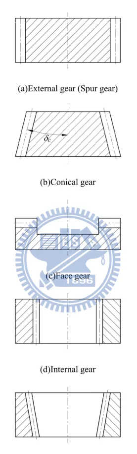
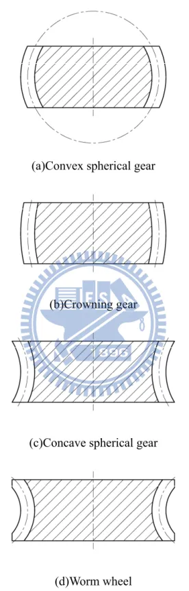
(25) helical gear set also has three types of mating combinations: convex teeth with concave teeth, convex teeth with convex teeth and convex teeth with helical gear teeth. Figures 1.2(a)-(e) shows five schematic illustrations for the changes of straight pitch traces in the axial section of different gear types. The axial section of a conventional external gear, i.e. spur (helical) gears, is shown in Fig. 1.2(a), and the pitch trace and gear axis are parallel to each other. When the pitch trace of the gear intersects the gear rotation axis with a cone angle c, then this type of gear is called the conical gear, as shown in Fig. 1.2(b). When the pitch trace and the gear rotation axis are perpendicular to each other, then the type of gear is called the face gear, as shown in Fig 1.2(c). If the cone angle c of an internal gear is equal to 180°, the pitch trace and gear rotation axis are parallel to each other, as shown in Fig. 1.2(d), and this type of gear is called the internal spur (helical) gear. While the cone angle c of an internal gear is more than 90° and less than 180°, this type of gear is called the internal conical gear, as shown in Fig. 1.2(e). Figures 1.2 shows the gear with linear pitch traces (i.e. straight lines), however, Fig. 1.3 shows the gear with quadratic pitch traces (e.g. arcs). Gears with quadratic pitch traces and convex outward are shown in Figs. 1.3(a) and (b), while gears with quadratic pitch traces and concave outward are illustrated in Figs. 1.3(c) and (d). When the pitch traces of a gear have a quadratic convex outward and form as a circle, this type of gear is called the convex spherical gear, as shown in Fig. 1.3(a). Figure 1.3(b) shows the gear with crowning tooth, and this gear also has a convex outward pitch trace with quadratic form. Whereas, the concave spherical gear has the quadratic pitch trace with concave outward, as shown in Fig. 1.3(c). As shown in Fig. 1.3(d), the worm wheel has the quadratic pitch trace with concave outward, and the radius of the pitch trace is equal to the pitch radius of the worm-type hob cutter. 3.
(26) (a)External gear (Spur gear). (b)Conical gear. (c)Face gear. (d)Internal gear. (e) Internal conical gear Fig. 1.2 The changes of straight pitch traces in axial section for different types of gears 4.
(27) (a)Convex spherical gear. (b)Crowning gear. (c)Concave spherical gear. (d)Worm wheel Fig. 1.3 The changes of quadratic pitch traces in axial section for different types of gears. 5.
(28) 1.2. Literatures review Although the manufacturing method of the spherical gears have been proposed by Mitome [1,2], however, only a few of researches on the spherical gears were performed up to now. Yang [7,8] and Yang et al. [9] proposed a ring-involute-teeth spherical gear with double degrees of freedom. Yang [10] applied the spherical gear with double degrees of freedom to the elbow mechanism. Tsai and Jehng [11] applied a rapid prototyping to manufacture a spherical gear with skew axes. Chao and Tsay [12,13] studied the contact characteristics of the spherical gear set generated by the imaginary rack cutters. Chao and Tsay [14] developed an automatic mesh-generation program to generate the contact model of the spherical gear set cut by two imaginary rack cutters, and investigated the contact and bending stresses of the gear pair by the FEA package ABAQUS/Standard. However, both spherical gears proposed by Yang [7-10] and Tsai [11] are quite different from that proposed in this study neither in generated mechanism, teeth profiles, kinematic characteristics nor meshing model of gear set. In the past, many studies have been made for spur gears, helical gears, conical gears, noncircular gears, curvilinear cylindrical gears and worm gears, including their respective mathematical models, tooth undercuttings, bearing contacts, stress analyses, manufactures or experiments. Wang and Fong [15] proposed a dual face-hobbing method for the cycloidal spur gears with crowning teeth. Mao [16] simulated the contact situation of a helical gear set, and investigated the reduction of fatigue wear of a spur gear set. Wang and Howard [17] studied the errors analysis of the spur gear drive between the 2-D and 3-D finite element approaches. Moreover, Chen and Tsai [18], and Ganesan and Vijayarangan [19] utilized the finite element method to investigate the involute spur gear by considering the frictional effects. The spur gear is a special case of helical gears with zero degree of helix angle. Tsay [20] 6.
(29) investigated the geometry, computer simulation, tooth contact analysis and stress analysis of the involute helical gear. Litvin et al. [21] simulated the meshing, contact stress and bending stress of the Novikov-Wildhaber helical gears. Chen and Tsay [22] investigated the tooth contact analysis and kinematic optimization of the helical gear pair with an involute pinion and a modified gear. Chen and Tsay [23] also discussed the stress analysis of a helical gear set with localized bearing contacts. Brauer [24] proposed a method to create a general finite element (FE) model for involute helical gears. Colbourne [25] studied the contact stress of the Novikov gear. Moreover, Liu and Tsay [26,27] studied the contact characteristic and tooth undercutting of beveloid gears. Tsai and Chin [28] discussed the surface geometry of bevel gears. Litvin et al. [29] investigated the bevel gears with low-noise and high-endurance by design, manufacture, stress analysis and experimental tests. Litvin et al. [30] applied FEM to investigate the loaded tooth contact analysis (LTCA) of the spiral bevel gear derive. Chang and Tsay [31] studied the tooth profile and undercutting of noncircular gears. Tseng and Tsay [32,33] studied the contact characteristics and tooth undercutting of the cylindrical curvilinear gear generated by two imaginary cutters. Tseng and Tsay [34,35] utilized the ZN-type hob cutter to cut the cylindrical curvilinear gear and enveloped to a two-parameter family of surface by computer simulation. They also investigated the surface deviations and tooth undercutting of the cylindrical curvilinear gear. Besides, Simon [36] discussed the influences of gear hobbing on worm gear characteristics. Janninck [37] proposed the surface separation topology method to simulate contact ellipses for the worm gear drive. Litvin [38] proposed a new geometry of face worm gear drives with conical and cylindrical worms, and investigated their generations, meshings and stress analyses. Fang and Tsay [39] utilized an oversize hob cutter to cut the ZN-type worm gear by computer simulations, and studied the bearing contacts of the ZN-type worm gear drive. Maki and Sakai [40] 7.
(30) proposed a new type of hourglass worm gearing with developable tooth surfaces. Chen and Tsay [41] studied the worm wheel working surfaces of the ZN-type hourglass worm gear set. Simon [42] studied the stress analysis of the double enveloping worm gears by the finite element method. Sun and Hung [43] applied the FE model of simplified gear pair with local refined meshes to investigate 2-D surface contact problem of two deformable bodies. Tsai and Hung [44] applied the finite element model with local refined meshes to investigate 3-D surface contact analysis of two elastically deformable bodies.. 1.3. Motivation The spherical gear is a new type of gear. Based on the advances of the spherical gear, this study proposes a gear by considering the assembly and transmission characteristics of the spherical gear and helical gear, called the spherical helical gear. The spherical helical gear has all geometry and transmission characteristics of the spherical gear, and the spherical helical gear set can be assembled in crossing axes mode which is the same as that of the helical gear set. Moreover, the hobbing method is considered for the generation of spherical helical gears due to its high cutting efficiency and low manufacturing cost. However, the cutting mechanism of a 5-axis CNC hobbing machine with multiple degrees of freedom may result in complex tooth surfaces because of the envelope surfaces of two-parameter family [45]. In this study, a complete mathematical model of the spherical helical gear with envelope surfaces of two-parameter family cut by the ZN-type worm-type hob cutter is developed firstly. Then the tooth undercutting and tooth pointing of the spherical helical gear and the contact situations of the spherical helical gear set under two assembly modes (parallel axes and crossing axes modes) and three mating combinations (convex tooth with convex tooth, convex tooth with concave tooth and convex tooth with helical gear 8.
(31) tooth) are also investigated. These contact situations, including kinematic errors, contact ratio, contact locus, dimension and orientation of contact ellipses, and contact and bending stress contours, are also investigated.. 1.4. Overviews This study totally includes six chapters. Chapter 1 is the introduction to the contents that contains the feature of the spherical helical gears, literatures reviews and motivation of this study. In Chapter 2, the mathematical model for the ZN-type worm-type hob cutter surfaces have been developed. According to the theory of gearing and generating mechanism of the CNC hobbing machine, the motions between the hob cutter and work piece, and the mathematical models for the convex and concave spherical helical gears can be obtained. Moreover, a 3-D computer graph of the spherical helical gear set with convex pinion and concave gear has been plotted by using the computer aided drawing technique. In Chapter 3, the condition equations of tooth undercutting and tooth pointing of the spherical helical gears are derived by utilizing the developed surface equations of the gears. Therefore, the limit curves of the tooth non-undercutting and tooth non-pointing of the spherical helical gears under different design parameters can be determined. In Chapter 4, the tooth contact analysis (TCA) method is applied to develop the tooth surface meshing model of the spherical helical gear set. The tooth surface meshing model includes assembly errors of the horizontal axial misalignment, vertical axial misalignment, axial shift along on the face width and the center distance error. Based on the developed tooth meshing model, the contact characteristics of the spherical helical gear set, under two axes (parallel and crossed axes) mounting modes 9.
(32) and three mating combinations (convex teeth with convex teeth, convex teeth with concave teeth and convex tooth with helical gear teeth), such as kinematic errors (KEs), contact ratios and contact loci can be obtained. The contact ellipses of the spherical helical gear sets can be obtained by using the TCA results and the surface separation topology method. Moreover, several numerical examples are presented to discuss the influences of the assembly errors on kinematic errors, contact ratios and contact ellipses of the spherical helical gear sets under two axes mounting modes and three mating combinations. In Chapter 5, the contact and bending stress contours of the proposed spherical helical gear sets are investigated by using the commercial FEA package, ABAQUS/Standard. Firstly, an automatic mesh-generation program is developed to generate the finite element contact model of the spherical helical gear sets by considering the developed surface equations of the gear sets. Therefore, an input file for ABAQUS/Standard computation is generated automatically by the developed mesh-generation program. Some numerical examples are presented to demonstrate the tooth stress with different gear design parameters. Chapter 6 concludes the proposal by summarizing the accomplished works in Chapters 2 and 3, and the future works for the advanced study.. 10.
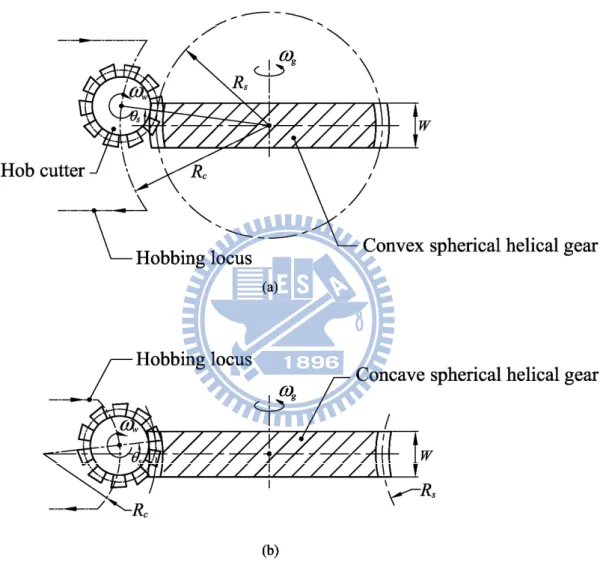
(33) CHAPTER 2 Mathematical Model of Spherical Helical Gears. 2.1 Introduction Hobbing is an economical method for gear manufacturing due to its versatility and high cutting efficiency. Hobbing method can be employed to generate various types of gears such as spur, helical, conical and worm gears. A hob cutter with straight-edged normal section can be used to generate the involute spur and helical gears. Different tooth profiles can be generated on the same CNC hobbing machine by changing the profile of hob cutters. However, the hobbing method is complicated since the gear generating motion is a multi-degree of freedom. Therefore, the method of two-parameter family envelope surfaces can be used to simulate hobbing process. Since the spherical helical gear is hobbed by a ZN-type worm-type hob cutter in this study, the convex and concave spherical helical gears can be considered as hobbing a helical gear with its hobbing path of positive or negative continuous hob shiftings in a quadric form, shifting from both sides of the tooth face width to its middle section, respectively [12,13]. Figure 2.1 shows two hobbing loci for hobbing the convex (Fig. 2.1(a)) and concave (Fig. 2.1(b)) spherical helical gears. Where the direction of positive profile shifting is defined as the direction outward the generated gear, whereas the direction of negative profile shifting is defined as the direction inward the generated gear. Moreover, compared with the standard tooth profile of a helical gear, the tooth profiles of the convex spherical helical gear at both ends of tooth face width have negative profile shifting, whereas the concave spherical helical gear has positive profile shifting at its both ends of tooth face width. Again, the hobbing path of a spherical helical gear is generated by hobbing a cylinder with a. 11.
(34) Fig. 2.1 Hobbing locus for spherical helical gear with (a)convex teeth and (b)concave teeth. 12.
(35) quadric form of continuous profile shifting (i.e. an arc) along the gear rotation axis instead of a straight line for the generation of the conventional helical gear. In this chapter, the mathematical model of the ZN-type worm-type hob cutter is derived firstly. Then the tooth surface equations of the convex and concave spherical helical gears are developed based on the generating mechanism of the CNC hobbing machine, the ZN-type worm-type hob cutter, and the theory of gearing.. 2.2 Mathematical model of the ZN-type worm-type hob cutter The normal profile of the ZN-type worm-type hob cutter is widely used for the gear manufacturing, and it is much more easier to manufacture a hob cutter with its normal section profile as a straight-lined shape. Therefore, a right-handed ZN-type worm-type hob cutter is used to simulate the manufacture of spherical helical gears in this study. The tooth surfaces of the hob cutter can be generated by a blade with the straight-lined shape, performing a screw motion with respect to the rotational axis of hob cutter. The cutting blade is installed on the normal section to the groove of the ZN-type worm, as shown in Fig. 2.2(a). The design parameter w is the lead angle of the worm. Figure 2.2(b) illustrates the normal section of a cutting blade that is rigidly connected to the coordinate system Sb ( X b , Yb , Z b ) , and the cutting blade is formed by two straight lines. The blade’s half apex angle n is formed by the straight-lined of the blade and Xb-axis, as shown in Fig. 2.2(b). Moreover, the distance lb measured from the initial point M0, moving along the straight line M o M 1 , to any point M1 is also a design parameter of the cutting blade. Therefore, the equation of the straight-line cutting blade can be represented in coordinate system Sb as follows:. 13.
(36) (a). (b). (c). (d). Fig. 2.2 Geometric relationships of the straight-edged cutting blade and the ZN-type worm-type hob cutter. 14.
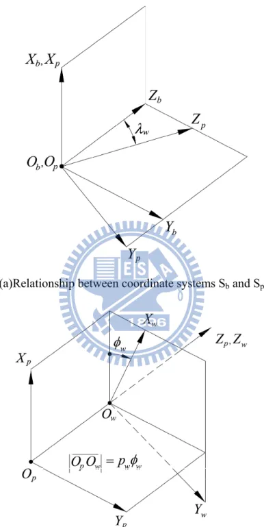
(37) rt lb cos n 0 , Rb lb sin n 1 . (2.1). where the upper “±” sign represents the left-side cutting blade, while the lower sign indicates the right-side cutting blade. Figure 2.2(c) shows the relationship between the cutting blade and the ZN-type worm-type hob cutter represented in the normal section of hob cutter’s rotation axis. Symbols ro, rf and rw express the outside radius, root radius and pitch radius of the ZN-type worm-type hob cutter, respectively. The cutting blade width bn equals the normal groove width of the hob cutter, and the design parameter rt can be obtained from the geometric relationship, as shown in Figs. 2.2(c) and (d) as follows:. rt rw2 . bn bn sin 2 w . 4 2 tan n. (2.2). Figure 2.3 shows the relations among coordinate systems Sb ( X b , Yb , Z b ) , S p ( X p , Yp , Z p ) and S w ( X w , Yw , Z w ) , where coordinate system Sb is the blade coordinate system, coordinate system S w is rigidly connected to the hob cutter, and coordinate system S p is the auxiliary reference coordinate system. Axes Zb and Zp form an angle w that is equal to the lead angle on the worm pitch cylinder, as shown in Fig. 2.3(a). Figure 2.3(b) shows that the movable coordinate system S w performs a screw motion with respect to the auxiliary reference coordinate system S p along the rotational axis of the hob cutter rotating through an angle w . Therefore, the locus equation of the cutting blade can be represented in coordinate system S w by applying the following homogeneous coordinate transformation matrix equation, transforming from coordinate system Sb to Sw: 15.
(38) (a)Relationship between coordinate systems Sb and Sp. (b)Relationship between coordinate systems Sp and Sw Fig. 2.3 Coordinate systems between the cutting blade and ZN-type worm-type hob cutter. 16.
(39) rt lb cos n cos w lb sin n sin w sin w r l cos sin l sin cos sin n w b n w w R w (lb , w ) M wp M pb R b t b , lb sin n cos w pww 1 . (2.3). where. M pb. 0 1 0 cos w 0 sin w 0 0. M wp. cos w sin w 0 0. 0 sin w cos w 0. 0 0 , 0 1. and sin w cos w 0 0. 0 0 0 0 , 1 p w w 0 1 . where, symbol pw represents the screw parameter of the ZN-type worm-type hob cutter. In Eq. (2.3), symbols lb and w are surface parameters of the hob cutter, and the upper “±” sign represents the left-side surface of the hob cutter, while the lower sign indicates the right-side surface of the hob cutter. Since the working interval of the ZN-type worm-type hob cutter must be limited between the outside radius ro and root radius rf of the worm, the upper and lower bounds of the design parameter lb can be limited by. lb ,max . and lb ,min . r. 2 o. . rt 2 sin 2 n sin 2 w ro2 cos 2 n rt cos n sin 2 n sin 2 w cos 2 n. r. 2 f. . rt 2 sin 2 n sin 2 w r f2 cos 2 n rt cos n sin 2 n sin 2 w cos 2 n. ,. (2.4). ,. (2.5). respectively. The surface normal vector N w of the hob cutter can be obtained and expressed 17.
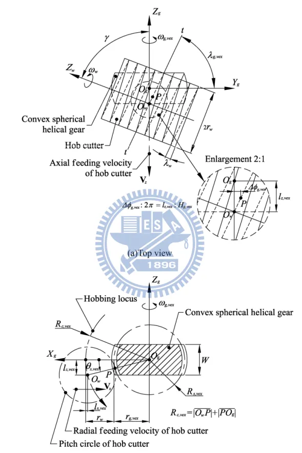
(40) in coordinate system S w as follows:. Nw . R w R w , lb w. (2.6). where cos n cos w sin n sin w sin w R w cos n sin w sin n cos w sin w , lb sin n cos w rt lb cos n sin w lb sin n cos w sin w R w rt lb cos n cos w lb sin n sin w sin w . and h pw. Again, the upper “±” sign in Eq. (2.6) represents the left-side surface of the hob cutter, while the lower sign indicates the right-side surface of the hob cutter.. 2.3 Tooth generation of the convex spherical helical gear 2.3.1 Generating relationship between hob cutter and convex spherical helical gear Figure 2.4 depicts the generating relationship between hob cutter and work piece of the convex spherical helical gear. Axes Zw and Zg are the rotation axis of the hob cutter and the work piece with angular velocities w and g, respectively, and these two axes form an angle called the crossing angle. The crossing angle is synthesized by the lead angles of the hob cutter w and the convex spherical helical gear g,vex (i.e.. =w+g,vex). Moreover, point Ow denotes the rotational center of the hob cutter’s swivel, and point Og is the center of the work piece. In Fig. 2.4(a), the common the hob cutter and the work piece are in tangency at point P. During the hobbing process, the center of hob cutter is moving along the hobbing locus with the linear axial and radial feeding velocities V x and Vz , as shown in Fig. 2.4. Moreover, the 18.
(41) (a)Top view. (b)Side view Fig. 2.4 Generating relationship between hob cutter and convex spherical helical gear. 19.
(42) tangent to both hob cutter and work piece is t-t, and the operating pitch cylinders of axial and radial feeding displacements of the hob cutter are designed as l z , vex and. l x , vex , respectively, and they are related by the following equations: lz , vex Rc , vex sin s , vex ,. (2.7). and l x ,vex Rc ,vex (1 cos s ,vex ) ,. (2.8). where symbol Rc,vex denotes the cutting radius, and symbol s,vex indicates the spherical angle for the convex spherical helical gear. According to Fig. 2.4(b), the cutting radius Rc,vex can be synthesized by the spherical radius Rs,vex and the pitch radius rw of the hob cutter for the convex spherical helical gear generation as follows:. Rc ,vex R s ,vex rw .. (2.9). According to Fig. 2.4(a), the rotation angles of the hob cutter and the work piece can be related as follows:. g , vex mwg , vex g , vex , where symbol mwg , vex . (2.10). Tw , while symbols Tw and Tg,vex denote the number of Tg , vex. threads of the hob cutter and number of teeth of the convex spherical helical gear, respectively. Symbols g,vex and indicate the rotational angles of the work piece and the spindle of the hob cutter, respectively. Symbol g,vex expresses the additional angle of the work piece (convex spherical helical gear) due to the generated gear with a helix angle. According to Fig. 2.4(a), the ratio of axial feeding displacement l z ,vex to the lead Hg,vex of the generated convex spherical helical gear is equal to that of the additional angle g,vex to a rotation cycle (i.e. 2) of the gear. Therefore, the 20.
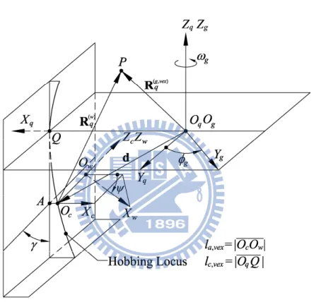
(43) additional angle g,vex for the convex spherical helical gear can be expressed by. g ,vex . l z ,vex , p g ,vex. (2.11). where symbol p g ,vex H g ,vex / 2π represents the screw parameter of the convex spherical helical gear.. 2.3.2 Equation of meshing for convex spherical helical gears Figure 2.5 illustrates the schematic relationships among coordinate systems. S w ( X w , Yw , Z w ) ,. Sc ( X c , Yc , Z c ) ,. S q ( X q , Yq , Z q ). and. S g ( X g , Yg , Z g ). for the. generation mechanism of the convex spherical helical gear. Coordinate systems Sw and Sg are attached to the hob cutter and convex spherical helical gear, respectively. Coordinate system Sc is an auxiliary coordinate system to describe the hob cutter’s rotational motion with a rotational angle , which coordinate system Sq is an auxiliary fixed coordinate system attached to the housing of a CNC hobbing machine. Moreover, symbol g,vex is the rotational angle of the generated gear (i.e. convex spherical helical gear). According to Fig. 2.5, the homogenous coordinate transformation matrices Mcw, Mqc and Mgq can be expressed as follows:. M cw. cos sin 0 0. sin cos 0 0. M qc. 0 1 0 cos 0 sin 0 0. 0 0 0 0 , 1 l a ,vex 0 1 0 sin cos 0. (2.12). lc ,vex l x ,vex 0 , l z ,vex 1 . and. 21. (2.13).
(44) Fig. 2.5 Coordinate systems between the hob cutter and convex spherical helical gear. 22.
(45) M gq. cos g ,vex sin g ,vex 0 0 . sin g ,vex cos g ,vex 0 0. where symbol l a ,vex Oc Ow. 0 0 1 0. 0 0 , 0 1. (2.14). is the axial displacement of the hob cutter, while. symbol lc ,vex Oq Q is the distance between points Oq and Q. Moreover, the feeding displacements l z , vex and l x ,vex of the hob cutter are expressed in Eqs. (2.7) and (2.8), respectively. In Fig. 2.5, point P denotes an instantaneous common point to the hob cutter and work piece (convex spherical helical gear) during a hobbing process. Therefore, surface coordinates R (qg ,vex ) of the work piece can be determined by transforming the hob’s surface from coordinate system Sw into the fixed coordinate system Sq as follows: R (qg ,vex ) M qc M cw R w [ xq. yq. z q 1]T ,. (2.15). where symbols xq, yq and zq are the X, Y and Z components of the hob cutter’s surface R (qg ,vex ) repressed in coordinate system Sq, respectively. Therefore, the velocity Vq( g ,vex ) at point P of the work piece can be obtained by Vq( g ,vex ) ω (qg ,vex ) R (qg ,vex ) [ yq g ,vex. xq g ,vex. 0]T ,. (2.16). where ω (qg , vex ) g , vexk q denotes the angular velocity of the work piece expressed in the fixed coordinate system Sq. Differentiating Eq. (2.10) with respect to time, the relationship among angular velocities g,vex, w and s,vex can be obtained as follows:. g ,vex . d g ,vex dt. mwg ,vex w . Rc ,vex cos s ,vex s ,vex , p g ,vex 23. (2.17).
(46) where symbol w symbol s ,vex . d indicates the angular velocity of the hob cutter, while dt. d s denotes the angular velocity of hob cutter’s generating motion dt. along the hobbing locus (see Fig. 2.4(b)). Equation (2.17) indicates the rotation angle. g , vex of work piece (convex spherical helical gear) in terms of two independent variables w and s, vex . Similarly, the velocity at point P that attached to the hob cutter, Vq(w) , can be obtained as follows: Vq( w) ω (qw) R (qw) Vx Vz ,. (2.18). where V x and Vz express the linear velocity of axial and radial feeding motion, ) indicates the angular velocity of the hob cutter expressed in the fixed and ω (w q. coordinate system Sq, as follows: ω (qw) L qcω c( w) [0 w sin . w cos ]T ,. (2.19). where the matrix L qc can be expressed as: 0 1 L qc 0 cos 0 sin . sin . cos 0. ) The surface coordinate of the hob cutter R (w can be obtained by q. R (qw) R (qg ,vex ) d ,. (2.20). where symbol d denotes the shortest vector measured from the center of the work piece to that of the hob cutter, and it can be expressed by 24.
數據

+7
相關文件
Reading Task 6: Genre Structure and Language Features. • Now let’s look at how language features (e.g. sentence patterns) are connected to the structure
volume suppressed mass: (TeV) 2 /M P ∼ 10 −4 eV → mm range can be experimentally tested for any number of extra dimensions - Light U(1) gauge bosons: no derivative couplings. =>
We explicitly saw the dimensional reason for the occurrence of the magnetic catalysis on the basis of the scaling argument. However, the precise form of gap depends
Helical Majorana fermions in TRI topological SCs show peculiar anisotropic magnetic response.. Under Zeeman fields, the helical MF shows
incapable to extract any quantities from QCD, nor to tackle the most interesting physics, namely, the spontaneously chiral symmetry breaking and the color confinement..
• Formation of massive primordial stars as origin of objects in the early universe. • Supernova explosions might be visible to the most
The difference resulted from the co- existence of two kinds of words in Buddhist scriptures a foreign words in which di- syllabic words are dominant, and most of them are the
(Another example of close harmony is the four-bar unaccompanied vocal introduction to “Paperback Writer”, a somewhat later Beatles song.) Overall, Lennon’s and McCartney’s
