國
立
交
通
大
學
資
訊
工
程
系
碩
士
論
文
提早載入:在深管線處理器設計下隱藏載入使用
延遲
Early Load:Hiding Load-to-Use Latency in Deep
Pipeline Processors
研 究 生:張順傑
指導教授:鍾崇斌 教授
提早載入:在深管線處理器設計下隱藏載入使用延遲
Early Load:Hiding Load-to-Use Latency in Deep Pipeline Processors
研 究 生:張順傑 Student:Shun-Chieh Chang
指導教授:鍾崇斌 博士 Advisor:Dr. Chung-Ping Chung
國 立 交 通 大 學
資 訊 工 程 系
碩 士 論 文
A Thesis
Submitted to Department of Computer and Information Engineering College of Electrical Engineering and Computer Science
National Chiao Tung University in partial Fulfillment of the Requirements
for the Degree of Master
in
Computer and Information Engineering
November 2008
Hsinchu, Taiwan, Republic of China
i
提早載入:在深管線處理器設計下隱藏載入使用延遲
學生:張順傑
指導教授:鍾崇斌 博士
國立交通大學資訊工程學系﹙研究所﹚碩士班
中文摘要
高效能處理器為了達到更高的指令產出量,其設計會趨近於有更寬的指令發出寬度 以及更深的管線設計。隨著管線變得越深以及越寬,指令的執行延遲變得越來越長,對 於in-order 處理器來說,變長的指令執行延遲會造成更多的 Stall 週期。一般的解決方 法是使用out-of-order 指令發出的管線設計,但是這對於一些應用來講是過於昂貴的, 例如嵌入式處理器;比較經濟的解決方法是只針對某些特定的指令做 out-of-order 發 出,這篇論文針對的是載入指令。載入指令在深管線處理器中有較長的執行延遲,且由 於執行頻率高而造成大量的 Stall 週期;如果接下來的指令與載入指令相依,則必須暫 停管線直到載入指令完成,這些暫停的週期稱為載入-使用延遲。 在這篇論文中,我們提出一個硬體設計的方法在載入/儲存單元空閒時提早執行載 入指令,這個方法我們稱之為提早載入。提早載入能夠提早辨識出載入指令,並允許載 入指令在還沒輪到循序執行前,提早從記憶體中載入所需要的資料;同時,我們提出一 個偵錯方法,能夠避免錯誤的提早載入運算,以確保提早載入資料的正確性,並且不會 造成額外的效能損失。提早載入方法可以隱藏載入-使用延遲以及降低載入/儲存單元的 競爭,並且只耗費額外不多的硬體。ii
Dhrystone Benchmark 我們的方法可以達到 11.64%的效能改善,而在 MiBench benchmark suite 方面,我們的方法最大可以達到 18.60%的效能改善,而整體平均的效能改善為 5.15%。同時提早載入的方法會增加所有 Load 指令額外 24.08%的記憶體存取。所耗費 的硬體約為 10K 個電晶體以及相關的控制線路。
iii
Early Load:Hiding Load-to-Use Latency in Deep Pipeline Processors
Student:Shun-Chieh Chang
Advisors:Dr. Chung-Ping Chung
Department of Computer Science and Information Engineering
National Chiao Tung University
Abstract
In order to achieve high instruction throughput, high performance processors tend to use more and deeper pipelines. As pipeline gets deeper and wider, the instruction execution latency becomes longer. The longer instruction execution latency induces more pipeline stall cycles in an in-order processor. A conventional solution is out-of-order instruction issue and execution; but it is too expensive for some applications, such as embedded processors. An economical solution for low-cost designs is to out-of-order execute only some critical instructions. We focus on load instructions, due to their frequent occurrences and long execution latency in a deep pipeline. If a subsequent instruction depends on the load instruction, it may need to stall in the pipeline to wait for the load outcome. The maximum possible number of stall cycles is called the load-to-use latency.
In this thesis, we propose a hardware method, called the early load, to hide load-to-use latency via executing load instructions early. Early load requires that load instructions be identified early and issued for execution early. In the meantime, an error detection method is proposed to stop or invalidate incorrect early loads, ensuring correctness without inducing extra performance degradation. Early load can both hide load-to-use latency and reduce
iv
load/store unit contention, at only a little hardware cost.
Our experiments show that for a 12-stage in-order dual-issue design, early load can give a 11.64% performance gain in Dhrystone benchmark; and a 18.60% maximal and 5.15% average gain for MiBench benchmark suite. Meanwhile, early load induces 24.08% additional memory accesses. The incurred hardware cost is about ten thousand transistors and corresponding control circuits.
v
致謝
首先我要感謝我的指導教授鍾崇斌教授,由於老師的督促與指導,使得這篇論文可 以順利完成。也感謝我的口試委員單智君教授、邱日清教授以及洪士灝教授,他們對於 這篇論文給予許多建議,使得這篇論文更為完整。 感謝實驗室的學長與學姊,尤其是李元化學長以及楊惠親學姊;從研究計畫到論文 發表到中美專利申請再到碩士論文,他們提供了許多的指導與幫助,同時也感謝喬偉豪 學長在論文與報告上給予的建議,感謝同學兩年來給予的幫助以及學弟給予的鼓勵與支 持。感謝智原科技的陳慶嘉經理以及工程師們在研究計畫中,給予的建議以及幫助。 最後最感謝的是我的家人,在兩年來對我的支持與鼓勵,在我最艱苦的時候也一直 是我最堅強的後盾,使我能夠順利完成研究所的學業。 張順傑 2008.11vi
Contents
中文摘要…… ...i Abstract……... iii 致謝…………. ...v Contents……...vi
List of Figures ... viii
List of Tables. ...x
Chapter 1 Introduction ...1
1.1 Convention Pipeline Design... 2
1.2 Anatomy of Load Instructions... 4
1.3 The Effect of Load-to-Use Latency... 6
1.4 Previous Work... 8
1.5 Research Goal... 9
1.6 Organization of This Thesis... 10
Chapter 2 Related Work... 11
2.1 For Load-to-Use Latency... 11
2.1.1 Zero-Cycle Load... 12
vii
2.2 For Cache-Miss Penalty... 14
2.2.1 Data Pre-fetching... 14
2.2.2 Runahead Execution... 14
2.2.3 Flea-Flicker Two-Pass Pipeline... 15
Chapter 3 Early Execution of Data Load ... 17
3.1 Early Load Identification... 19
3.2 Avoidance and Invalidation Mechanism... 26
Chapter 4 Simulation and Evaluation... 31
4.1 Experimental Environment... 31
4.1.1 Benchmark Suite... 31
4.1.2 Simulator Configuration... 32
4.2 Experimental Results... 33
4.2.1 Distance of Early Load... 33
4.2.2 Size of Early Load Queue... 35
4.2.3 Length of Load-to-use Latency... 36
4.2.4 Result on SPEC2000 Benchmark Suite... 37
Chapter 5 Discussion ... 41
Chapter 6 Conclusion ... 43
viii
List of Figures
Figure 1. Convention 5-stage Pipeline Design...2
Figure 2. 12-stage Pipeline Design...3
Figure 3. Major operations of load instructions with execution order...4
Figure 4. The two parts of load latency...5
Figure 5. The effect of load latency...7
Figure 6. The Percentage of Load Instructions ...7
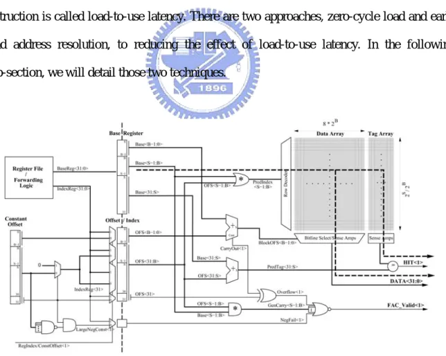
Figure 7. Implementation of the fast address calculation mechanism ... 11
Figure 8. Implementing zero-cycle load mechanism ... 12
Figure 9. Execution and memory access timeline for runahead execution and flea-flicker multi-pass pipeline ... 15
Figure 10. Systems with early load mechanism ... 18
Figure 11. The percentage of two addressing mode ... 20
Figure 12. Duplicate the pre-decoder parallel with tag comparison ... 21
Figure 13. Structure of early load queue... 22
Figure 14. Set early load lookahead pointer into the instruction queue... 23
Figure 15. (a) Without early load mechanism (b) With early load mechanism24 Figure 16. Two examples of the violation conditions... 27
ix
Figure 18. Performance improvement with different early load distance... 34 Figure 19. Trend of different early load distance ... 34 Figure 20. Performance improvement with different size of early load queue 35 Figure 21. Trend of sizes of the early load queue... 36 Figure 22. Performance improvement with different length of load-to-use
x
List of Tables
Table 1. Simulation configuration detail... 33 Table 2. Performance improvement in SPEC2000 benchmark suite ... 37 Table 3. Performance improvement with different early load distance... 38 Table 4. Performance improvement with different size of early load queue... 39 Table 5. Performance improvement with different length of load-to-use
1
Chapter 1 Introduction
In order to achieve high instruction throughput, high performance processors tend to use more and deeper pipelines. Meanwhile, the cache memory has been moved toward high densities instead of short access time. These trends have relative increased cache access latencies as measured in processor clock cycle. The growing load latency dominates the overall performance because it may induce large stall cycles at run time. Following instructions, if depends on load instruction, need to stall pipeline to wait the data fetched by the load instruction. So, hiding the load-to-use latency is one way to improve the processor performance.
This thesis proposes a hardware method, called the early load, to hide the load-to-use latency with only a little hardware cost. Early load allows load instructions to load the data from the cache before it enters the execution stage. In the meantime, a error detection method has been proposed to avoid starting the early load operation that may be fetched the wrong data from the cache and invalidate the early load operation that already executed and it fetched the wrong data from cache.
The remainder of this chapter presents the background and motivation necessary to prepare the reader for the remaining chapters. Section 1.1 introduces the conventional pipeline design. Section 1.2 introduces load instructions and the load-to-use latencies. Section 1.3 explores the effect of load latency. Section 1.4 capsules the existing approaches for reducing the effect of load-to-use latency. Section 1.5 describes the research goal. Section 1.6 details the organization of the remaining chapters.
2
1.1 Convention Pipeline Design
Pipelining is an implementation technique that exploits parallelism among the instructions in a sequential instruction stream. RISC instructions classically take five steps:
1. Fetch instruction from memory.
2. Read registers while decoding the instruction. The format of RISC instructions allows reading and decoding to occur simultaneously.
3. Execute the operation or calculate an address. 4. Access an operand in data memory.
5. Write the result into a register.
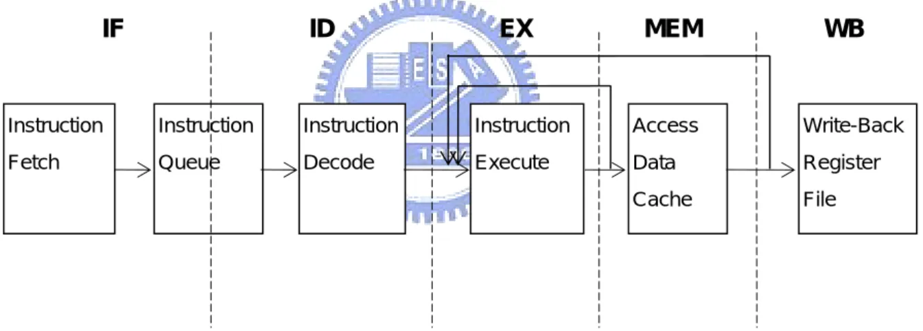
Figure 1. Convention 5-stage Pipeline Design
Figure 1 illustrates a conventional 5-stage pipeline design of processors. Referring to Figure 1, the pipeline has the instruction fetch stage (IF), the instruction decode stage (ID), the instruction execution stage (EX), the memory access stage (MEM), and the write-back stage (WB). In the conventional pipeline design, the instruction fetch stage and the instruction decode stage is separated by the instruction queue so as to reduce the performance loss of the processor caused by mismatch of issue rate and fetch rate. The architecture is also called
Instruction Fetch Instruction Queue Instruction Decode Instruction Execute Access Data Cache Write-Back Register File IF ID EX MEM WB
3
decoupled architecture. Accordingly, most instructions do not enter the instruction decode stage right after they are fetched into the processor; instead, they wait in the instruction queue until the previous instructions are issued. The instruction fetch stage fetches instructions from an instruction cache memory (or a main memory) and pushes the instructions into the instruction queue. The instruction queue stores the instructions fetched by the instruction fetch stage based on the first in first out (FIFO) rule and provides the instructions to the instruction decode stage sequentially.
Generally speaking, before executing an instruction, the processor needs to decode the instruction by using the instruction decoder. The decoded instruction is sent to the instruction execution stage. The instruction execution stage includes the arithmetic and logic unit (ALU) which executes an instruction operation according to the decoding result of the instruction decode stage. In the memory access stage, load instructions access the cache memory (or main memory) to get the data and store instructions check the address hits in the cache or not. If the instruction operation executed by the instruction execution stage generates a calculation result, the write-back stage then writes the calculation result back into the register file or cache memory (or main memory).
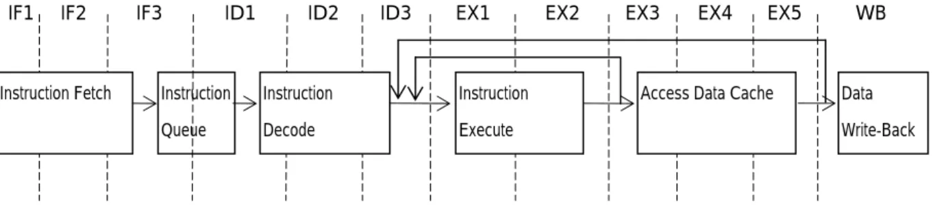
When the pipeline gets deeper, each stage will be spilt into several stages. Figure 2 illustrates the 12-stage pipeline design. In Figure 2, the 12-stage pipeline has 3 stages for instruction fetch, 3 stages for instruction decode, 2 stages for instruction execution, 2 stages for memory access, and one stage for data write-back.
Figure 2. 12-stage Pipeline Design Instruction Fetch Instruction
Queue
Instruction Decode
Instruction Execute
Access Data Cache Data Write-Back
IF2 IF3 ID1 ID2 ID3 EX1 EX2 EX3 EX4 EX5 WB
4
1.2 Anatomy of Load Instructions
Load instructions move data from memory to registers. Most of them have two inputs, base address and offset, are added or subtracted together to produce the effective address which used to access the cache memory (or main memory). In most instruction set architecture, the base address always supplies by the general proposal register, called base register. And the offset can be an immediate value, i.e. register±immediate addressing mode, or supplies by the general proposal register, called index register, i.e. register±register addressing mode.
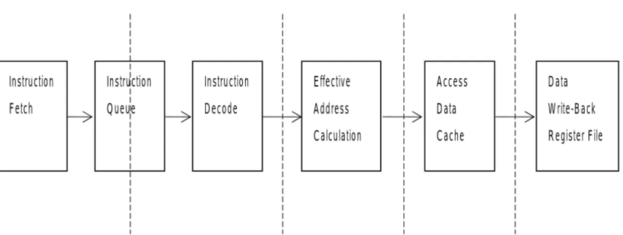
A load instruction is composed of several operations. First, it has been fetched by the instruction fetcher from instruction memory and has been pushed into the instruction queue. Second, it has been decoded by the instruction decoder and read the register file to get the source operands, like the base register and index register. Third, it calculates the effective address by arithmetic logic unit for the following data memory access. Forth, it fetches the target data from the data memory. Finally, it writes back the loaded data to the destination register in the register file. Figure 3 shows the major operations of load instructions with its execution order.
Figure 3. Major operations of load instructions with execution order Instruction Fetch Instruction Queue Instruction Decode Effective Address Calculation Access Data Cache Data Write-Back Register File
5
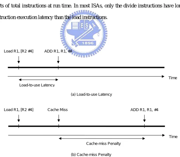
Load instructions sometimes incurred long waiting time for the following instruction that depends on it, as they need to calculate the memory address and fetch target data from data memory. The latency is composed of address calculation, cache access, and opportunistic external memory access. If a subsequent instruction depends on the load instruction, it may need to stall the pipeline in front of the execution stage until the data produced by the load instruction becomes available. That will induce large stall cycles at run time. A conventional solution is out-of-order instruction issue and execution. However, out-of-order execution is too expensive for some applications, such as embedded processors. An economical solution for low-cost designs is to out-of-order execute only some critical instructions, we focus on the load instructions. Load instructions have long instruction execution latency and take large parts of total instructions at run time. In most ISAs, only the divide instructions have longer instruction execution latency than the load instructions.
Figure 4. The two parts of load latency
Time Cache-miss Penalty
Time
Load R1, [R2 #4] ADD R1, R1, #4
Load-to-use Latency
(a) Load-to-use Latency
(b) Cache-miss Penalty
6
The maximum possible number of cycles that following instructions, if depend on the load, need to stall pipeline to wait the data fetched by the load instruction is called load-to-use latency, it determines by pipeline design. It depends on the number of execution stage, number of memory access stage, expected cache-miss penalty and forwarding network design. The cache-miss penalty is the additional latency due to cache miss. The best case is hit in the highest level cache, and the expected cache-miss penalty is zero in this case. The worst case is hit in main memory, because the main memory miss will cause the context switch. In this case, the expected cache-miss penalty is hundreds of cycles. Figure 4 shows those two parts of load latency. The latency of load instructions increases as pipeline gets deeper. In the 5-stage pipeline, the load-to-use latency is just only 1 cycle, shown in Figure 1. But, the load-to-use latency increases to 5 cycles in the 12-stage pipeline, shown in Figure 4.
1.3 The Effect of Load-to-Use Latency
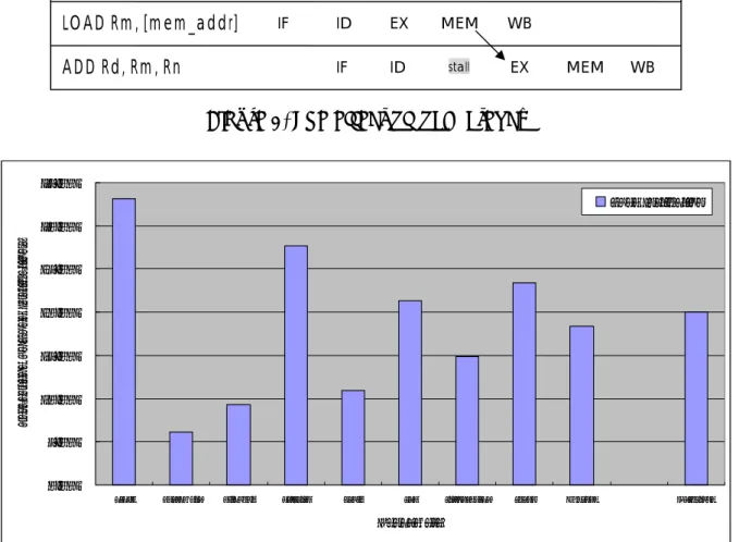
Typically, the latency between data loading and data processing increases along with the depth of the pipeline in the conventional processor design, and which may induce large stall cycles and affect the processor performance considerably. The following code sequence illustrates the latency of load instructions:
LOAD Rm, [mem_addr]
ADD Rd, Rm, Rn
Assume the processor pipeline as shown in Figure 1 is a conventional in-order 5-stage pipeline design. The instruction fetch stage fetches LOAD instruction and ADD instruction sequentially from the instruction memory and pushes them into the instruction queue. After the instruction decode stage decodes these instructions, the instruction execution stage first executes the LOAD instruction. The load/store unit fetches the target data from the address mem_addr in the data memory and stores the data into the register Rm in the register file. The
7
data loading operation is completed in the memory access stage. If the instruction execution stage and memory access stage need n cycles to complete the LOAD instruction, the dependent ADD instruction needs to stall the pipeline for n cycles in front of the instruction execution stage until Rm value becomes available. Numbers of stall cycles n will increase as pipeline gets deeper. Figure 5 illustrates how load latency affects program execution.
Figure 5. The effect of load latency
0.00% 5.00% 10.00% 15.00% 20.00% 25.00% 30.00% 35.00%
crc32 basicmath bitcount dijkstra qsort sha stringsearch susan Average Dhrystone
Benchmark P er ce nt age o f L oa d Ins tr uc ti on s Load Instruction
Figure 6. The Percentage of Load Instructions
We assume the processor has 12-stage in-order dual-issue pipeline design, and the latency of load instructions is 5 cycles in this processor. We analyzed the programs, the Dhrystone benchmark [9] and the MiBench benchmark suite [8], in our simulator, and found
Instruction Clock Cycle
1 2 3 4 5 6 7 LOAD Rm, [mem_addr] ADD Rd, Rm, Rn IF ID EX MEM IF ID stall EX MEM WB WB
8
that: the load-to-use latency induces large stall cycles (2.51 cycles/load) at run time; the load instructions take 20.0% in Dhrystone benchmark and 18.35% in MiBench benchmark suite of total instructions. Figure 6 shows the load instructions take percentage of total instructions. So, hiding the load-to-use latency is one way to improve processor performance.
1.4 Previous Work
Hiding the load-to-use latency has two major design directions: early or speculatively execute the load instructions and fill the load-to-use latency with independent instructions. This thesis focuses on the early or speculative execute the load instruction to hide the load-to-use latency. Previous work that hides or reduces the latency of load instructions can be categorized into two kinds of approaches: software-based approaches and hardware-based approaches.
The software-based approach is known as static instruction scheduling in compiler time. For example, the unrolling and jamming for loops [5] enlarges a basic block so that more instruction can be scheduled to hide long execution latency. However, not all load instructions can be scheduled across loop iterations; for example, it depends on the loop termination condition. In addition, software scheduling is not efficient for a processor of limited architectural register space.
The hardware-based approach like zero-cycle load [1] and early load address resolution [6] alleviates the load-to-use latency by fast address calculation but only for limited number of cycles. Runahead execution [2] and flea-flicker two-pass pipeline [3] can tolerate the cache-miss penalty by executing the independent instruction when the processor is stalled by data cache miss. However, the long delay of mode switching, checkpointing, and recovery makes it unsuitable for the relatively short load-to-use latency.
9
1.5 Research Goal
In this thesis, we present a hardware approach, called early load, to hide the load-to-use latency in an in-order issue processor. We found some opportunities that we can use.
First, the base register of load instruction is sometimes ready for a while before load instruction is issued. We can read the base register and calculate the effective address early; it has possibility to be right. Second, in order to alleviate the performance loss due to the mismatch of fetch rate and issue rate, the fetch stage and the decode stage is separated by the instruction queue in conventional processor pipeline design, called decouple architecture, as shown in Figure 1. When instructions are fetched into processor, they wait in the instruction queue until the previous instructions are issued. We can make use of the time that instructions wait in the instruction queue to load the target data early. We use those two opportunities to design our early load mechanism.
With the early load mechanism, we identify the load instruction and execution condition in fetch cycle by pre-decoding instructions, and load the target data when the instructions wait in the instruction queue. Meanwhile, we also propose a mechanism to avoid and invalidate the early load operations that fetch the wrong data from data memory. In the following section, we will describe the early load mechanism in detail. If the early load operation is success to be executed, the load-to-use latency problem is alleviated.
Apply early load mechanism in the system, it allows early executing the load instruction when load/store unit is idle. The early load mechanism can hide the load-to-use latency and reduce the load/store unit contention. Hence, the early load mechanism can improve the processor performance.
10
1.6 Organization of This Thesis
The remainder of this thesis is organized as follows: Section 2 describes the related work. Section 3 details the early load mechanism. Section 4 presents the results of our experiments. Section 5 discusses the strength and weakness of our approach. Finally, Section 6 concludes our work.
11
Chapter 2 Related Work
We can consider the latency of load instructions into two parts: load-to-use latency and cache-miss penalty. The techniques proposed to reduce the effect of latency of load instructions can be separate into two kinds of approaches: for load-to-use latency and for cache-miss penalty.
2.1 For Load-to-Use Latency
The latency that following instruction waits for their operands produced by the load instruction is called load-to-use latency. There are two approaches, zero-cycle load and early load address resolution, to reducing the effect of load-to-use latency. In the following sub-section, we will detail those two techniques.
12
2.1.1 Zero-Cycle Load
Zero-cycle load [1] combines fast address calculation with an early-issue mechanism to make pipeline capable of hiding latency of many loads that hit in the data cache. The fast address calculation [13] mechanism predicts effective addresses early in the pipeline, thereby allowing loads to commence execution and complete. Figure 7 shows the implementation of the fast address calculation mechanism for a direct-mapped cache [13].
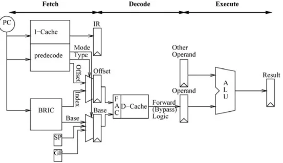
Figure 8. Implementing zero-cycle load mechanism
Figure 8 shows the approach to implementing zero-cycle load in an in-order issue pipeline [1]. The instruction cache return not only the instruction but also the pre-decode information. The base register and index cache (BRIC) is a small cache indexed by the load instruction’s address, recorded the base register value and the index register value (register±register addressing mode) by history. In the decode stage, the load instructions access the cache with fast address calculation mechanism and the result is produced at the end of the decode stage.
13
With zero-load mechanism, the depending instructions have no visible latency because it allows load instructions to produce the value before it enters the execution stage. However, not all loads can execute with zero latency. The early-issue mechanism brings additional register and memory hazard, and the zero-cycle load occasionally fails. To ensure the correctness of the mechanism, it needs a recovery mechanism that will induce performance degradation. In order to achieve zero-cycle load, load instructions must complete in only two cycles.
2.1.2 Early Load Address Resolution
Early load address resolution [6] presents a non-speculative technique that partially hides the load-to-use latency by allowing the early issue of load instruction. This technique avoids the pipeline stall due to load instruction’s base register dependency.
Register tracking provides a method to safely compute the address of memory load. It enables early computations of the values of register by tracking the simple operations in decode time. With register tracking mechanism, the dependency of the base register of load instructions can be easy settled. Several tracking schemes are proposed:
y Stack pointer tracking allows safe early resolution of stack references by track of
the value of the ESP register.
y Absolute address tracking allows the early resolution of constant-address loads.
y Displacement-based tracking tackles all loads with addresses of the form
register±immediate by tracking the values of all general-propose registers.
The register tracking takes place in decode stage needs to track the register values immediately and the reduced cycle number from decode to execution stage is not much. Meanwhile, it has a larger hardware overhead to track and compute the register value.
14
2.2 For Cache-Miss Penalty
The additional latency due to cache miss is called cache-miss penalty. There are three approaches, data pre-fetching, runahead execution, and flea-flicker, to reducing the effect of cache-miss penalty. In the following sub-section, we will detail those three techniques.
2.2.1 Data Pre-fetching
Data pre-fetching [4] cuts the overall cache-miss penalty by bringing likely-to-be-used data from distant memory to an upper level of the memory hierarchy ahead of time. Since the goal of data pre-fetching is only to bring closer the likely-to-be-used data, no recovery scheme is required; because a misprediction (i.e. a useless pre-fetch) does not have any severe impact except for wasted bandwidth and the possible eviction of some data from the memory hierarchy. However, data pre-fetching does not eliminate the load-to-use latency of the first level cache access.
2.2.2 Runahead Execution
Runahead execution [2] has been proposed to tolerate cache-miss penalty. In runahead execution, the processor checkpoints the processor state and enters the runahead mode when a long latency cache miss occurs. Execution continues bypassing the miss and dependent instructions, and pre-fetches data. When the cache-miss-causing instruction completes, the processor exits the runahead mode, restores the processor states, and execution restarts from the point of the load miss.
Runahead execution allows the processor to execute the instructions that do not depend on the data of the long latency cache misses. Once the processor returns to the normal mode,
15
it can computation continues while the load misses discovered during runahead execution no longer stall the pipeline. Runahead execution provides performance improvements in two main areas: instruction and data prefetching. The instruction prefetching improvement comes from prefetching runahead instructions into the L2 cache and the trace (or instruction) cache, and training the branch predictors during runahead mode. Data-prefetching improvement comes from prefetching runahead load requests into the L2 cache and L1 data cache, and training the hardware data prefetchers’ buffers during runahead mode. However, the long delay of mode switching, checkpointing, and recovery makes it unsuitable for the relatively short load-to-use latency.
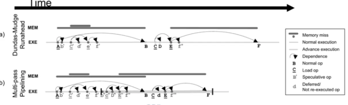
Figure 9. Execution and memory access timeline for runahead execution and flea-flicker multi-pass pipeline
2.2.3 Flea-Flicker Two-Pass Pipeline
Flea-flicker two-pass pipeline [3] exploits compile-time scheduling on simple in-order hardware while achieving excellent cache miss tolerance through persistent advance pre-execution beyond otherwise stalled instructions. The pipeline systematically makes multiple passes through instructions that follow a stalled instruction. Each passes increase the speed of the subsequent passes with its valid execution results preserved in a result buffer.
16
Figure 9 shows the different between runahead execution and flea-flicker two-pass pipeline. Multi-pass pipelining tolerates long latencies without the overhead associated with dynamic scheduling or register renaming. Unlike most pre-execution schemes, multi-pass pipelining provides for the persistence of valid advance execution results. Reusing these results increases efficiency, hides the latency of multiple-cycle instructions and, through a novel mechanism, accelerates in-order execution. A notion of instruction criticality further enhances the handling of miss latencies and reduces fruitless speculative execution by indicating when there is little opportunity for advance execution. The flea-flicker two-pass pipeline has limitation the same with runahead execution, the long delay of mode switching, checkpointing, and recovery makes it unsuitable for the relatively short load-to-use latency, too.
17
Chapter 3 Early Execution of Data Load
In section 1.5, we mentioned some opportunities that can be used. First, the base register of load instructions is sometimes ready for a while before load instruction is issued. Second, when the instructions are fetched into processor, they wait in the instruction queue until the previous instructions are issued. Hence, we can read the base register and calculate the effective address early. And make use of the time that the load instruction waits in the instruction queue to fetch the target data early from the data memory and store it in a buffer. If the early operation is valid and complete before the corresponding load instruction is issued, and the data is already in the buffer without executing the load instruction. Hence, the problem of load-to-use latency is alleviated.
To design the early load mechanism, we have three major research goals. First, identify the load instruction and execution condition before the early load operation starts. Second, start the early load operation at the time that made the early load operation complete on time when the load instruction is issued. Third, deal with all of the early load operations that fetched the wrong data from data cache.
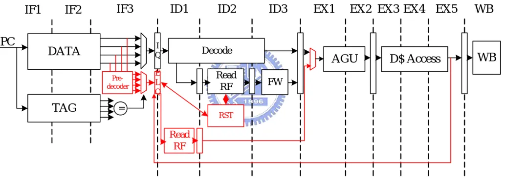
The early load mechanism has two parts: the early load identification and the avoidance and invalidation mechanism. The early load identification identifies the load instruction early and execution condition, and executes the load instruction to load data at the time that made the early load operation complete on time when the load instruction is issued. The avoidance and invalidation mechanism is a detection method to avoid starting the early load operation that may be fetched the wrong data from cache and invalidate the early load operation that already executed and it fetched the wrong data from cache. Figure 10 shows the system that is 12-stage in-order dual-issue pipeline with the early load mechanism.
18 Pre-decoder I Q E L Q Decode Read RF RST
WB
AGU
D$ Access
IF3
ID1
ID2
ID3
EX1
EX2 EX3 EX4
EX5
WB
Read RF
PC
=IF1
IF2
DATA
TAG
FW19
The early load mechanism logic shown in Figure 10 must to identify the load instruction and its execution condition early. The pre-decoder in the instruction fetch stage used to identity the load instruction in front of the instruction queue. The early load queue (ELQ) has been used to record the early load candidates and its early loaded data in order in the pipeline. The register status table (RST) used to record all of the register status and renaming information from the register file to the early load queue. The information also used to avoid and invalidate the incorrect early load operation. Detailed design description will be provided in the following sub-sections.
3.1 Early Load Identification
In order to early execute the load instruction, we need to indentify the load instruction before the early load operation is executed. Therefore, indentify the load instruction that stored in the instruction queue is difficult to design. We must be read the instruction from the instruction queue and decode it. Hence, pre-decode the load instruction before instruction push into instruction queue has been chosen in our design.
When the instruction fetch stage fetches an instruction, the instruction fetch stage first pre-decodes the instruction to identify the load instruction and its execution condition. Whether to store the instruction into an early load queue is determined according to the pre-decode result. If the instruction does not belong to the target type, the instruction is stored only into the instruction queue (the instruction is not stored into the early load queue). Then, the instruction is executed by the instruction decode stage and the instruction execution stage. If the instruction belongs to the target type, the instruction is stored not only into the instruction queue but also into the early load queue. The load instruction stored in the early load queue, called the early load candidate, will load data early when the instruction waits in the instruction queue.
20
Because the early loaded data may be incorrect, we need a method to make sure the correctness of the early loaded data. An avoidance mechanism has been proposed to avoid starting the early load operation that may be fetched the wrong data, and the invalidation mechanism has been proposed to invalidate the early load operation that already started executing and it fetched the wrong data from the cache. We will detail the avoidance and invalidation mechanism in the section 3.2.
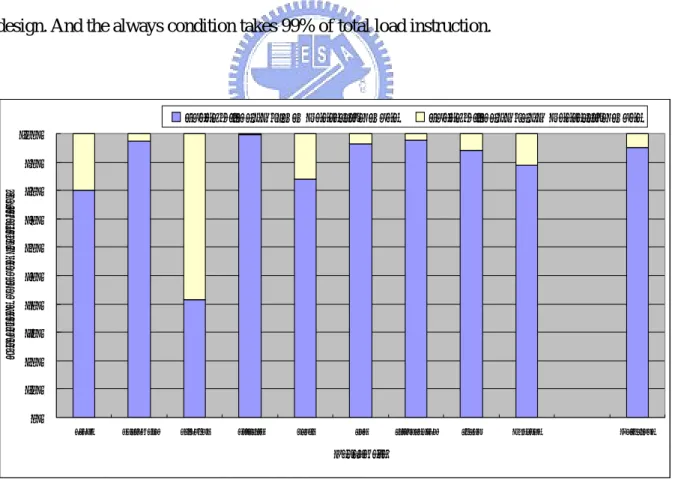
The target type of the early load instruction is load instructions which take 18.35% of total instructions at run time. The load instructions need to have register+immediate addressing mode, because of low accuracy for register±register addressing mode (< 10%). The register+immediate addressing mode take 86.53% of total load instructions, shown in Figure 11. Finally, the execution condition of instructions must be always, because of easy for design. And the always condition takes 99% of total load instruction.
0% 10% 20% 30% 40% 50% 60% 70% 80% 90% 100%
crc32 basicmath bitcount dijkstra qsort sha stringsearch susan Average Dhrystone
Benchmark P er ce nt age of L oa d Ins tr uc ti ons
Loads with REG±IMM Addressing Mode Loads with REG±REG Addressing Mode
21
The pre-decoder needs to indentify load instructions and execution condition before the instructions push into the instruction queue. Meanwhile, we don’t want to increase the clock cycle time. Figure 12 shows the design of the pre-decoder. We duplicate the pre-decoder and pre-decode instructions parallel with cache tag comparison. After the tag comparison, choose the pre-decode information based on the result of tag comparison. That we can indentify the load instruction in fetch cycle and no need to increase the clock cycle time.
Figure 12. Duplicate the pre-decoder parallel with tag comparison
The early load queue is a queue parallels with the instruction queue. It records the early load candidates in order in the pipeline. Each entry of early load queue includes the following information:
- Active[0]: The ELQ entry has been active for execute.
- Status[1:0]: The status of the ELQ entry; prepare, busy, complete, or invalid.
Tag
Data
Instruction Cache
Pre-decodPre-decode
Is early load candidate? ELQ PC IQ
IF
ID
=
=
=
22
- BReg[3:0]: The base register index of load instruction. - Offset[11:0]: The offset value of the load instruction.
- Adr_mode[3:0]: The addressing mode of the load instruction. - Adr[31:0]: The memory address of the load instruction. - EL_Data[31:0]: The early loaded data of the load instruction.
The early load queue has two pointers: head pointer and tail pointer. The head pointer point at the oldest load instruction in the pipeline; adjusted when the load instruction committed. The tail pointer points at the 1st empty entry which is prepared for the next load instruction. Figure 13 shows the structure of early load queue.
Figure 13. Structure of early load queue
The pre-decoder in the IF stage identifies the instruction type and condition code, and decodes the base register index, offset, and the addressing mode. If the load instruction has the address of the form register+immediate, it will be push into the early load queue and the status bit will be set to prepare state.
Following problem is when to execute the early load operation. We need to start the early load operation at suitable time. If the time to start the early load operation is too early, the base register of load instruction has higher possibility to be not ready. If the time to start the early load operation is too late, the early load operation can not complete the early load
1’b0 1’b1 Active 32’h00 32’hFF… Addr 32’h00…0 32’hFF…F EL_data 12’0BF 12’h00F Offset 4’b1110 4’b1110 Adr_mode 4’b1000 2’b11 4’b1111 2’b01 BReg Status Head Tail
23
operation on time when the load instruction is issued. Hence, we set an early load lookahead pointer into the instruction queue to decide when to start the early load operation, like Figure 14. The EL pointer pointed the instruction behind the head pointer with N instructions. The N value is called early load distance, it is a fixed value determined by simulation. When the pointer points a load instruction in the instruction queue, set its corresponding early load queue entry to active. When the load/store unit is idle, chooses the oldest and active early load candidate in the early load queue to start the early load operation and set its status to busy. After the operation finished, the loaded data will be stored into the corresponding entry in early load queue and set its status to complete.
Figure 14. Set early load lookahead pointer into the instruction queue
When the load instruction goes into the ID stage, the status of early load queue entry is checked. If the status is valid, following register access of this destination register will be renamed to the corresponding early load queue entry and the load instruction does not need to execute again. Following instructions depending on this register will get the data from the early load queue. If the status is invalid, load instruction will be executed actually. And the early load queue entry will be deallocate when the load instructions are committed.
head
tail
EL LOAD
Instruction Queue
Early load Queue EL Distance
: : :
24
The early load procedure has six steps. First, identify the load instruction before instruction has been pushed into instruction queue. The early load candidate will be pushed into early load queue and set the early load queue entry’s status to prepare but not active. Second, when the EL pointer points a load instruction in the instruction queue, sets its corresponding early load queue entry to active. Third, checks the load/store unit is idle or not each cycle. If the load/store unit is idle, choose the oldest and active early load candidate in the early load queue to execute the early load operation and set its status to busy. When the early load operation complete, set its status of early load queue entry to complete. Forth, check the correctness of early loaded data. If the early loaded data is incorrect, set the early load queue entry’s status to invalid. The avoidance and invalidation mechanism will describe in detail in next section. Fifth, when the load instruction into ID-stage, check its corresponding early load queue entry is complete or not. If yes, renaming the load instruction’s destination register to early load queue entry. And keep the renaming information in the register status table. Finally, when the load instruction is committed, deallocate the early load queue entry.
Figure 15. (a) Without early load mechanism (b) With early load mechanism Cycle
Instructions
1 2 3 4 5 6 7 8 9
CMP r1, #10 IF ID EXE MEM WB
BEQ loop IF ID EXE MEM WB
LOAD r2, [r0 #0] IF ID EXE MEM WB
ADD r3, r3, r2 IF ID Stall Stall EXE MEM WB
ADD r1, r1, #1 IF Stall Stall ID EXE MEM WB
(a)
CMP r1, #10 IF ID EXE MEM WB
BEQ loop IF ID EXE MEM WB
LOAD r2, [r0 #0] IF ID (EL) EXE MEM WB
ADD r3, r3, r2 IF ID EXE MEM WB
ADD r1, r1, #1 IF ID EXE MEM WB
25
Figure 15 shows two examples with and without early load mechanism. Figure 15 (a) is a process timing table of each instruction in the pipeline when the processor executes the same program segment without using the early load method. Figure 15 (b) is a process timing table of each instruction in a pipeline when the processor executes a particular program segment by using the early load method described above. In the tables, IF represents “instruction fetch”, ID represents “instruction decode”, EXE represents “instruction execution”, MEM represents “memory access”, and WB represents “data write-back”. In addition, EL represents that the early load method is executed.
As shown in Figure 15 (a), because the instruction “LOAD r2, [r0 #0]” needs to be fetched from the data cache into the register r2, the next instructions “ADD r3, r3, r2” and “ADD r1, r1, #1” are stalled pipeline for several cycles until the data fetching operation of the instruction “LOAD r2, [r0 #0]” is completed. As shown in Figure 15 (b), since the early load method described in foregoing description is adopted, the instruction “LOAD r2, [r0 #0]” already fetches its early loaded data from the data cache into the early load queue through the early load operation during the instruction decoding phase ID, so that the instruction data fetching operation MEM needs not to fetch data from the data cache again. Accordingly, the following instruction “ADD r3, r3, r2” does not have to wait and the instruction executing operation EXE is carried out right after the instruction decoding operation ID is completed. In the embodiment described above, the early loaded data corresponding to an instruction is early loaded when the instruction waits in the instruction queue. Accordingly, the stall cycles between data loading and data processing in the design of pipeline processor can be avoided. The deeper the depth of the pipeline is, the number of stall cycles will increase and the better the performance of the early load method will get.
The last problem is how to make sure the correctness of early load operation. Because we executed the load instruction to fetch data from cache system early, the early loaded data has possibility to be wrong. We need a method to make sure the correctness of the early
26
loaded data and recover it when the incorrect early load operation happened. The simple method is that we execute the load instruction actually and compare the data and early loaded data. If the values of two data are the same, the early load operation is right. Otherwise, the early load operation is wrong and need to recover. The recovery mechanism is flush the pipeline, and re-fetch the instructions after the load instruction. Just like the branch miss prediction recovery.
The drawbacks of the checking method are higher memory (cache) pressure and larger recover penalty. Each of load instructions needs to access memory twice that induces the higher memory pressure. If the early load operation is wrong, the recover penalty is the same with branch miss determined by the depth of pipeline. If we can check the correctness of early load operation before the load instruction issued to the execution stage, we can reduce the larger recover penalty due to wrong early load operation by re-executing the load instruction immediately. The following section will provide a method to avoid starting the early load operation that may be fetch the wrong data from cache to reduce the increasing cache pressure due to early load mechanism, and invalidate the early load operation that already executed and it fetch the wrong data.
3.2 Avoidance and Invalidation Mechanism
To design the avoidance and invalidation mechanism, we analyzed the early load mechanism first and found that two violations may be produced by allowing a load instruction to fetch data from the cache early. One of the violations is base register dependency violation and the other one is memory dependency violation. Base register dependency violation takes place when older instruction is calculating the value of the base register and accordingly the instruction which performs “early load” may obtain the old value of the base register and access the memory according to the old value. In this case, wrong data is fetched from the
27
wrong address. Memory dependency violation takes place when the instruction which performs “early load” accesses the same memory address as another store instruction which older than the early load instruction, so that the data fetched by the instruction which performs “early load” may not be updated. The avoidance mechanism is used for avoid starting the early load operation that may be wrong and the invalidation mechanism is used to invalidate the early load operation that already executed and it fetch the wrong data.
CMP r1, #10 STR r3, [r1, #0]
BEQ loop LOAD r2, [r1 #0]
ADD r1, r1, #1 ADD r1, r1, #1
LOAD r2, [r1 #0] ADD r3, r3, r2
ADD r3, r3, r2 B loop
(a) Base Register Dependency Violation (b) Memory Dependency Violation
Figure 16. Two examples of the violation conditions
Figure 16 are two examples of those two violation conditions. In Figure 16(a), if the r1 value is not ready when the LOAD instruction is undergoing the early load operation. The early load operation of the LOAD instruction is wrong due to base register dependency violation. In Figure 16(b), when the LOAD instruction is undergoing the early load operation, the execution of STR instruction is not complete. The value at the address [r1, #0] is not yet updated. So, the early load operation of the LOAD instruction is wrong due to the memory dependency violation. Our design must be check those two dependency violation and avoid them happening.
The avoidance and invalidation mechanism checks these two violation conditions. The register status table keeps track of the register status, checks data of the base register dependency, and records the renaming information. Each entry of register status table includes following information:
28
- Status[1:0]: The status of the register; ready, busy, or rename. - ELQ_ID[3:0]: The ELQ entry that this register renamed to.
- Stage[2:0]: A count down counter subtract one each cycle, used to indicate which instruction is calculating the register value in the pipeline.
The register status table is a table which records all of the resister status and renaming information from the register file to early load queue. The register status table has been updated in the instruction decode stage and reset in the write-back stage by the instruction’s destination register. When the instruction has been issued, set status of its destination register in the register status table to busy and the stage to execution latency. The status bits will decrease one per cycle. When the stage bits becomes zero, reset the register status to ready. If the register has been renamed to early load queue entry, keep the renaming information in the ELQ_ID and set the register status to rename. Figure 17 shows the structure of the register status table.
R0
R1
R2
R3 R4 R5 R6 R7 R8 R9 R10 R11
R12
R13
R14 R15
Status[1:0]
ELQ_ID[3:0]
Stage[2:0]
Figure 17. Structure of the register status table
In the avoidance and invalidation mechanism, the occurrences of these two dependency violations have been checked. If these dependency violations occurred, the corresponding entry in the early load queue is set to invalid in advance. Correct data is fetched from the cache or the memory when the instruction execution stage and memory access stage execute the instruction.
29
Avoidance mechanism: avoid starting the early load operation that may be fetched the wrong data.
Case 1: by checking the base register status to avoid starting the early load operation that may be fetched the wrong data:
When any instruction passes through the instruction decode stage, setting the status field of the destination register thereof in the register status table to busy. Before the early load operation starts, check the base register status in the register status table. If the status of the base register is busy, setting the status files of the corresponding entry in the early load queue to invalid without starting the early load operation.
Invalidation mechanism: invalidate the early load operation that already started and fetched the wrong data.
Case 2: by checking the base register version to invalidate the early load operation that already started and fetched the wrong data:
When any instruction passes through the instruction decode stage, setting the status field of the destination register thereof in the register status table to busy, searching the early load queue to determine whether there is any instruction uses this base register and it already started the early load operation. If yes, setting the status field of the corresponding entry in the early load queue to invalid. Case 3: by checking the load address content to invalidate the early load operation that already started and fetched the wrong data:
When a store instruction generates a memory address in the instruction execution stage, searching the early load queue to determine whether there is the same memory address in the early load queue and it already started the early load operation. If yes, set the status field of the corresponding entry in the early load queue to invalid.
30
In overview, the early load mechanism is adopted in the processor pipeline, the target data is early loaded from the cache into early load queue in the processor when the instruction waits to be executed in the instruction queue and the avoidance and invalidation mechanism is provided to avoid and invalidate the incorrect early load operation. Thereby, if the pipeline successfully early loads the target data into the early load queue, the delay between data loading and data processing can be reduced effectively, and even when the pipeline cannot early load the target data into the early load queue successfully, the performance of the processor is not affected.
31
Chapter 4 Simulation and Evaluation
In chapter 3, we proposed the mechanism and architecture of the early load mechanism which allows a load instruction to fetch data from the cache early. In this chapter, we present the simulation results and evaluations of our design. In section 4.1, we describe the simulation environment and the benchmark programs that we used to evaluate the performance improvement in the simulation. In section 4.2, we examined the effects for some variable, like the distance of early load, the size of early load queue, and the length of load-to-use latency.
4.1 Experimental Environment
4.1.1 Simulation Tool
The simulator used in this thesis is derived from the SimpleScalar/ARM [7], a suite of functional and timing simulation tools for the ARM ISA. The timing simulator executes only user-level instructions, performing a detailed timing simulation of microprocessor with two levels of instruction and data cache memory. Simulation is execution-driven, including execution down any speculative path until the detection of a fault, TLB miss, branch misprediction, or etc.
For precise simulation result report, we rewrite the SimpleScalar to support cycle-based simulation different from instruction-based simulation. We evaluated the performance improvement of early load mechanism by extending SimpleScalar/ARM [7] to support early load mechanism and examining the performance of Dhrystone [9], MiBench benchmark suite [8], and SPEC2000 benchmark suite [10] running on this simulator. To observe the performance in more detail, we examined effects of the distance of early load, the size of
32 early load queue, and the length of load-to-use latency.
4.1.2 Benchmark Suite
The benchmark programs that we used are from MiBench benchmark suite [8]. These benchmarks are divided into six suites with each suite targeting a specific area of the embedded market. The six categories are Automotive and Industrial Control, Consumer Devices, Office Automation, Networking, Security, and Telecommunications. All the programs are available as standard C source code so that it focuses on portable applications written in high-level languages as processor architecture and software developers are moving in this direction. Where appropriate, there provide a small and large data set. The small data set represents a light-weight, useful embedded application of benchmark, while the large data set provides a more stressful, real-world application. We use the large data set in this thesis. All programs of MiBench benchmark suites are publicly available and widely used on general purpose processors. Since many past embedded applications have been written directly in assembly language, it has been difficult to collect a portable set of benchmarks for embedded domain.
4.1.3 Simulator Configuration
Table 1 summarizes the configuration of the target machine used in the simulator. We use the ARMv5E ISA processor with 2-issue in-order pipeline in our simulator. The L1 caches are separated into L1 instruction cache and L1 data cache without L2 cache. Each of L1 cache is 32KB 4-way set associated cache. And the branch prediction is prefect. We evaluated the performance impact with different distance of early load (1 to 7 instructions), different sizes
33
of early load queue (4, 8, 12, and 16 entries), and two different lengths of the load-to-use latency (3 and 5 cycles).
Table 1. Simulation configuration detail
Instruction Set Architecture ARM ISA version 5 with Enhanced DSP instruction set Fetch/Decode/Issue Width 2 instructions per cycle
L1 I-cache 32K 4-way set associate. L1 D-cache 32K 4-way set associate.
Instruction Queue Size 24 entries, EL Distance = 1~7 instructions Early Load Queue Size 4/8/12/16 entries
8 stages (500MHz)
2 stages fetch/2 stages decode /3 stages execution/1 stage writeback
12 stages (800MHz)
3 stages fetch/3 stages decode /5 stages execution/1 stage writeback
Depth of pipeline
20 stages (1.2GHz)
5 stages fetch/5 stages decode /8 stages execution/2 stage writeback
Issue Model In-order issue of up 2 operations per cycle
Function Units 2-integer ALU, 1-load/store unit, and 1-multiplier; no floating units
4.2 Experimental Results
4.2.1 Distance of Early Load
In this section, we evaluate the performance impact of different early load distance from 1 to 7 instructions. The processor under evaluation has 12-stage pipeline and 16-entry early load queue. Figure 18 and Table 3 shows the performance improvement for various distance of early load.
We need to start the early load operation at suitable time. The simulation result shows the fixed distance of early load is 4 instructions for MiBench benchmark suite. In our target machine, the execution latency of early load operation is 6 cycles. The average IPC is about 0.7 instruction per cycle. And the operand is read form register in ID2 stage. So, the best
34
distance of early load is 4 instructions. Figure 19 shows the trend of distance of early load from 1 to 7 instructions. 0.00% 2.00% 4.00% 6.00% 8.00% 10.00% 12.00% 14.00% 16.00% 18.00% 20.00%
crc32 basicmath bitcount dijkstra qsort sha stringsearch susan Average
Benchmark Per fo rm an ce Im pr o vem en t
D_EL=1 D_EL=2 D_EL=3 D_EL=4 D_EL=5 D_EL=6 D_EL=7
Figure 18. Performance improvement with different early load distance
0.00% 1.00% 2.00% 3.00% 4.00% 5.00% 6.00% 7.00% 1 2 3 4 5 6 7
Distance of Early Load
P er for m acne Im pr ovem ent Performacne Improvement
35
4.2.2 Size of Early Load Queue
In this section, we evaluate the performance impact of the size of early load queue for three sizes, 4, 8, 12 and 16 entries. The processor under evaluation has 12-stage pipeline and the early load distance is 4 instructions. Figure 20 and Table 4 shows the performance improvement for various sizes of early load queue.
0.00% 2.00% 4.00% 6.00% 8.00% 10.00% 12.00% 14.00% 16.00% 18.00% 20.00%
crc32 basicmath bitcount dijkstra qsort sha stringsearch susan Average Benchmark Pe rf or m ac ne I mp rove me nt
4-entry ELQ 8-entry ELQ 12-entry ELQ 16-entry ELQ
Figure 20. Performance improvement with different size of early load queue
The early load queue needs to keep all of the early load candidates in the back-end pipeline. In our target machine, maximum of instructions in the back-end pipeline is 40. The load instruction takes 18.35% of total instructions. So, 8 load instructions is in the base-end pipeline in average. The simulation result shows the suitable size of early load queue is 8 or 12 entries. Because of the distribution of load instructions in the pipeline is not uniform. Figure 21 shows the trend of sizes of the early load queue from 4 to 16 entries.
36 0.00% 1.00% 2.00% 3.00% 4.00% 5.00% 6.00% 7.00% 4 8 12 16
Size of Early Load Queue
Per fo rm acn e Im pr ov emen t Performacne Improvement
Figure 21. Trend of sizes of the early load queue
4.2.3 Length of Load-to-use Latency
In this section, we evaluate the performance impact of length of load-to-use latency for two lengths, 3 cycles and 5 cycles. The processor under evaluation has 12-entry early load queue and early load distance is 4. Figure 22 and Table 5 shows the performance improvement for two length of load-to-use latency.
The performance improvement increases as the length of load-to-use latency increases. In the 8-stage pipeline, the load-to-use distance is 3 cycles. The static instruction scheduling of compiler can easily hide the load-to-use latency. In the 12-stage pipeline, the load-to-use distance increases to 5 cycles. In this situation, solving the problem of load-to-use latency by the static instruction scheduling becomes harder. The load-to-use latency problem is more seriously in deeper pipeline, and the early load mechanisms we proposed is more efficient in deeper pipeline, see the Table 5.
37 0.00% 2.00% 4.00% 6.00% 8.00% 10.00% 12.00% 14.00% 16.00% 18.00% 20.00%
crc32 basicmath bitcount dijkstra qsort sha stringsearch susan Average
Benchmark P er fo rman ce Im p ro vemen t
8-stage Pipeline 12-stage Pipeline
Figure 22. Performance improvement with different length of load-to-use latency
4.2.4 Result on SPEC2000 Benchmark Suite
In previous section, we evaluated the mechanism in number of context. And we get the configuration that can achieve the most performance improvement. In this section, we evaluate the mechanism in another benchmark suite, SPEC2000 benchmark suite [10], to see the performance improvement. We use the 12 stages of the pipeline, 12 entries of the early load queue, and early load distance is 4. Table 2 shows the performance improvement for the SPEC2000 Benchmark suite.Table 2. Performance improvement in SPEC2000 benchmark suite Evaluation
Benchmark
Without Early Load With Early Load Performance Improvement
bzip2 0.42 0.44 6.42% gap 0.49 0.61 24.8% gzip 0.39 0.42 7.54% mesa 0.65 0.65 0.54% equake 0.61 0.65 7.01% apsi 0.32 0.32 0.01% Average 9.27%
38
Table 3. Performance improvement with different early load distance Evaluation
Benchmark Number of Instruction (Million)
W/O EL N = 1 N = 2 N = 3 N = 4 N = 5 N = 6 N = 7 crc32 403.85 0.83 0.24% 0.26% 0.27% 0.25% 0.25% 0.25% 0.25% basicmath 3922.86 0.69 1.47% 1.55% 1.60% 1.54% 1.43% 1.49% 1.39% bitcount 641.5 0.72 2.20% 2.20% 2.20% 2.20% 2.20% 2.20% 2.20% dijkstra 237.44 0.43 14.90% 16.77% 18.66% 18.60% 18.59% 11.32% 11.32% qsort 361.99 0.62 7.50% 7.74% 8.25% 8.34% 8.18% 8.27% 8.31% sha 129.57 0.95 0.51% 0.37% 0.37% 0.38% 0.38% 0.38% 0.38% stringsearch 51.07 0.44 0.93% 5.12% 4.87% 4.93% 4.96% 4.96% 4.94% susan 112.18 0.77 4.15% 5.07% 5.09% 5.32% 5.32% 5.32% 3.74% Average 4.49% 4.88% 5.16% 5.19% 5.15% 4.28% 4.05%
39
Table 4. Performance improvement with different size of early load queue Evaluation
Benchmark Number of Instruction (Million)
W/O EL 4-entry ELQ 8-entry ELQ 12-entry ELQ 16-entry ELQ
crc32 403.85 0.83 0.21% 0.25% 0.25% 0.25% basicmath 3922.86 0.69 1.33% 1.51% 1.54% 1.54% bitcount 641.5 0.72 2.20% 2.20% 2.20% 2.20% dijkstra 237.44 0.43 11.26% 18.60% 18.60% 18.60% qsort 361.99 0.62 7.13% 8.01% 8.43% 8.34% sha 129.57 0.95 0.18% 0.38% 0.38% 0.38% stringsearch 51.07 0.44 3.79% 4.91% 4.86% 4.92% susan 112.18 0.77 3.69% 3.29% 4.97% 5.32% Average 3.72% 4.89% 5.15% 5.19%
40
Table 5. Performance improvement with different length of load-to-use latency Evaluation
3-Cycle 5-Cycles 8-Cycles Benchmark Number of Instruction (Million)
W/O EL W/ EL W/O EL W/O EL W/O EL Pef. Imp. W/O EL W/O EL Pef. Imp.
crc32 403.85 1.65 1.65 0.83 0.83 0.83 0.25% 0.62 0.75 20.3% basicmath 3922.86 0.88 0.88 0.69 0.69 0.69 1.54% 0.56 0.57 2.60% bitcount 641.5 0.82 0.82 0.72 0.72 0.72 2.20% 0.54 0.56 2.42% dijkstra 237.44 0.86 0.92 0.43 0.43 0.43 18.6% 0.33 0.48 46.7% qsort 361.99 0.86 0.88 0.62 0.62 0.62 8.43% 0.49 0.57 16.5% sha 129.57 1.23 1.23 0.95 0.95 0.95 0.38% 0.69 0.72 3.97% stringsearch 51.07 0.63 0.63 0.44 0.44 0.44 4.86% 0.36 0.42 13.0% susan 112.18 1.03 1.04 0.77 0.77 0.77 4.97% 0.61 0.67 9.02% Average 1.31% 5.15% 14.3%
41
Chapter 5 Discussion
We evaluated the mechanism in numbers of contexts: the distance of early load, the size of early load queue, and the length of load-to-use latency. In our experiment, we studied the impact of performance with different configurations.
We need to start the early load operation at suitable time. Too early or too late make the performance improvement of early load is not so good. The simulation result shows the fixed distance of early load is 4 instructions for MiBench benchmark suite. In our target machine, the execution latency of early load operation is 6 cycles. The average IPC is 0.7 instructions per cycle. And the operand is read form register in ID2 stage. So, the best distance of early load is 4 instructions. Fixed distance of early load is easy to design, but the early load distance is a best value in average not a best value for every situation. Variable distance of early load is hard to design. In order to design the variable distance of early load, we need to know the execution behavior for the instruction in the future. But it is hard to predict. However, dynamically decided the distance of early load can get the better performance.
When the early load mechanism has a small early load queue, less load instructions can execute earlier because the early load queue is full frequently. Large early load queue has less chance to be full. But larger early load queue costs more hardware overhead and slow access time. The proper size of early load queue can be determined by simulation. In our simulation result shows the suitable size of early load queue is 12 entries.
The problem of load-to-use latency becomes serious, as the depth of pipeline increases. In a shallow pipeline, the static instruction scheduling of compiler can easily hide the load-to-use latency. But the compiler is hard to find the independent instructions to fill out the more pipeline bubbles in deeper pipeline. In a deep pipeline, one valid early load operation can hide more stall cycles
42
In our analysis, early load mechanism allows 29.68% of total load instruction can be early executed. Another 70.32% can be separated into two parts. One is register±register addressing mode. It takes 13.47% of total load instructions. Another is invalid early load operations due to two dependency violations; it takes 56.85% of load instructions. And most of them are array accesses.
In the early load mechanism, we can check the early operation is valid or not before the load instruction enters the execution stage. When the early load is valid, we can succeed to hide the load-to-use latency. Otherwise, if the early operation is invalid, the load instruction will be executed without inducing extra performance degradation. The early load mechanism increases the pressure on data cache access. The additional cache access is 24.08%. Since we load the data hits in cache, the pressure of memory access does not increase.
43
Chapter 6 Conclusion
Increasing depth of pipeline leads to high instruction throughput and high clock rate. But the long load-to-use latency of deep pipeline processor impacts the processor performance seriously due to pipeline stalls. Hiding the load-to-use latency becomes one of the most challenging problems for high performance processors.
In this thesis, we proposed a hardware method, call early load, to hide the load-to-use latency. Early load allows load instructions loads data from memory system while the load instruction waits in instruction queue. Meanwhile, the avoidance and invalidation mechanism provides an error detection method to make sure the early loaded data is correct. When the early loaded data is correct, the load-to-use latency between the load instruction and the dependent instructions becomes zero. And if the early loaded data is invalid, the load instruction will be executed without inducing extra performance degradation
The early load can give a 11.64% performance gain in Dhrystone benchmark. We also evaluated the performance improvement in MiBench benchmark suite. It achieves 18.60% performance improvement in dijkstra of the MiBench and 5.15% performance improvement in average. And the additional cache access is 24.08%. We evaluated early load mechanism in number of contexts. The proper size of early load queue and suitable distance of early load can be determined by simulation. In our experiment, the 4-instruction early load distance and 12-entry early load queue has been used in our simulator.
The early load mechanism can be extended to the pre-fetch mechanism. In our approach, when the data cache miss occurs, the early load operation may be invalid. We can make some change to the early load mechanism to wait the early load operation to be ready when the load instruction enters the ID stage. By little modification, we may hide additional cache-miss penalty.
44
In the future, we can combine the register tracking mechanism with early load mechanism. Register tracking enables early computation of the values of register by tracking the simple operations of the form register±immediate or stack pointer. We can use the register tracking mechanism to track the base register value used to execute the early load operation. It can avoid the invalid early load operation due to the base register dependency violation.