Design of an Area-Efficient ASIC Architecture for Context-Based Binary Arithmetic Coding
4
0
0
全文
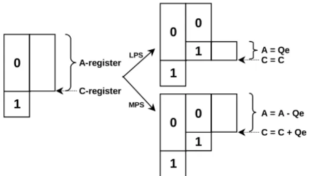
(2) 2: ARITHMETIC ENCODING SCHEME Arithmetic coding is a kind of lossless data compression technique for either bi-level or multilevel symbols. The concept of arithmetic coding originates from the recursive probability interval subdivision, by which each input symbol can be mapped to a real-number interval. In the JPEG2000 standard, the real-number interval is defined in between 0.75 and 1.5. Thus, by means of persistent interval subdivision, an input message will be ultimately mapped to a high-precision real value in the range from 0.75 to 1.5. For the binary (or bi-level) arithmetic coding procedure, the current probability interval is subdivided into two unequal sub-intervals. The more probable symbol (MPS) is mapped to a larger interval subdivision, whereas the less probable symbol (LPS) is allotted to the smaller one. In other words, the precision for the interval subdivision needs to be high whenever the divided interval is small. On the other hand, as the MPS appears more frequently, the interval subdivision is expressed based on a coarser precision, i.e., fewer bits are enough to encode the interval subdivision. This just coincides with the object of data compression. The manipulation of context-based arithmetic coder in JPEG2000 is conducted as follows. First, a pair of inputs (i.e., decision, D, along with context, CX) comes from the output of the previous EBCOT stage. Both of them are processed in parallel to generate the wanted compressed data (CD). Context, CX, is then selected from the estimated probability during the encoding stage of D. Three working registers together with some ROM’s and RAM’s are required to accomplish the encoding procedure. The main functions with respect to these three registers are summarized in Table 1. Table 1: Function of registers used in the encoder Register Name. Bit Width. Register C. 28. Register A. 16. Register B. 8. Function Record the current interval base Record the current interval size Record the compressed output data. As for the encoding procedure shown in Fig. 1, the size of the current interval is kept in the register A. The register C is always maintained to point to the bottom of the current interval after completing each coding phase. Once every input symbol is fed into the encoder, the current interval A is subdivided into two new sub-intervals with length A-Qe and Qe, where Qe denotes the probability estimation of an LPS. Depending on whether an MPS or LPS is encoded, one of these two sub-intervals is chosen as the newest interval of the register A. To avoid the underflow of register A during encoding the LPS and MPS, a renormalization. procedure ought to initiate here. Moreover, a terminal procedure (or called the flush procedure) is brought in at the end of every input message. The purpose of this procedure is to flush and output all the coded data which remain in the register C.. 0 0. LPS. 0 1. A = Qe C=C. 0. A = A - Qe. A-register. 1 C-register. 1. MPS. 0. 1. C = C + Qe. 1. Fig. 1 Encoding process of the arithmetic coder.. 3: PROPOSED ARCHITECTURE The existing architectures for the MQ-coder can be categorized into FSM (also known as non-pipeline) and pipelined design methodologies. The FSM needs at least two cycles to process each input sample. Although this design style easily solves the renormalization problem, the throughput rate is low. Hence the alternative design style, namely pipelined, is often adopted to support real-time applications.. 3.1: Proposed Architecture In general, it is difficult to design the MQ coder based on a regular-flow pipelined architecture due to the uncertain number of compressed output bytes. Another concern against the pipelined structure is dataflow dependency. For instance, because the compressed data formation will maintain a new content in the coding register C after each computation, extra waiting cycle time is required for the new low-bound update so as to deal with the next computation. This, in turn, makes the design of these two modules very difficult, especially for the part of pipelining. Apparently, separating the computations of these two modules will facilitate our design. In light of such an idea, we present a novel solution that employs a different pipeline structure. Based on this proposed structure, all the modules used in the proposed architecture are expected to carry out within a single clock cycle. More specifically, we let the interval-size probability subdivision and compressed data formation modules computed in parallel. These two modules perform individually regardless of their mutual dependency. The foregoing mechanism makes every input sample manageable within one clock cycle as a pipelined design, thus providing a high-throughput rate. This is important for real-time image processing. In. - 130 -.
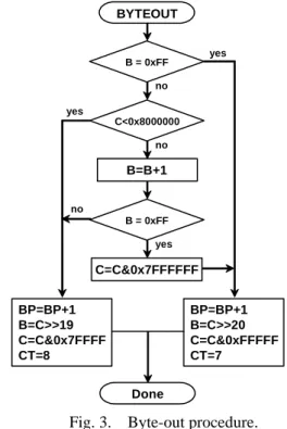
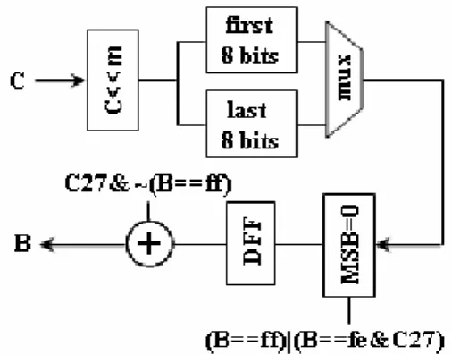
(3) particular, we can always accommodate such an MQ coder to high-performance embedded block coding (EBCOT) to construct a high-throughput and high-performance Tier-1 coder in JPEG2000. According to the above discussion, the proposed arithmetic encoding architecture, like a 3-stage pipelined design style, is illustrated in Fig. 2. This proposed architecture is composed of the context model update, interval-size probability subdivision, and compressed data formation modules. These modules, which correspond to the dash boxes shown in Fig. 2, are described below.. rather than an FSM circuit. The compressed data formation module mainly contains two byte-out submodules, a flush hardware, and a four-size FIFO buffer. The proper size of FIFO’s has been discussed in [4]. In general, this four-size FIFO shall be enough because a byte-out formation requires at least one input sample. Thus, there is time enough to gracefully send the byte-out data into the FIFO. The byte-out submodule will be described later in more detail. Also, a flush procedure is adopted in the proposed architecture to make the design fully compatible with the arithmetic encoder defined in ISO/IEC 155444-1.. 3.2: Byte-out Circuit Submodule The compressed data output of the MQ encoder is produced by the BYTEOUT procedure shown in Fig. 3, which is invoked from the previous RENORME procedure. As seen from this procedure, it is apparent that the position of the expression B = B+1 must be placed after the second logic expression B = 0xFF so as to make all the decisions of this procedure executable within one clock cycle time. However, this will cause an error because the execution sequence of the expression B=B+1 is changed. To resolve this dilemma, the original logic expression should be modified as B = 0xFE.. Fig. 2. Proposed ASIC architecture for the MQ-coder. The context-model module consists of four ROM’s and two RAM’s. The context model stored in RAM’s is updated after the comparison between input decision value (D) and MPS symbol under a context value. The interval-size probability subdivision module is responsible for computing the probable interval size stored in the register A and maintaining the low bound of the interval stored in the coding register C. The coding maintainer contains a barrel shifter and a new low-bound update. The interval-size division facility is also equipped with a barrel shifter to ease the generation of a new interval-size subdivision. The number of shifts equals the quantity of leading zeros of the new interval size A. This means that the whole renormalization used in our design runs at one clock cycle time, regardless of the number of compressed data outputs. Nevertheless, the compressed data formation can be independently extracted from the intermediate outcome of the interval-size probability subdivision module, as shown in Fig. 2, without affecting the subsequent interval-size probability subdivision. This scheme elegantly gets over the problem of unfixed pipeline stages caused by the uncertain number of renormalizations during the encoding phase. Note that this interval-size probability subdivision module employs a finite state machine (FSM) placed between two pipeline registers. Our design differs from the traditional pipelined structure in that the circuit is often a simple combinational logic. BYTEOUT yes. B = 0xFF no yes C<0x8000000 no. B=B+1 no B = 0xFF yes. C=C&0x7FFFFFF BP=BP+1 B=C>>19 C=C&0x7FFFF CT=8. BP=BP+1 B=C>>20 C=C&0xFFFFF CT=7 Done. Fig. 3. Byte-out procedure. The block diagram of the proposed byte-out circuit is shown in Fig. 4. This circuit merely contains simple logic circuits deduced from the foregoing discussion. In order to further simplify the proposed circuit, we convert many logic expressions to some simple logic operations. For instance, the expression B=B+1 with a. - 131 -.
(4) condition C<0x8000000 is merged into expression B=B+C27, where C27 is the MSB of C register. Thus, the original decision logic circuit is skipped. Such a manner is often used in the whole proposed architecture to reduce the hardware cost.. the uncertain number of renormalizations. Compared with the existing pipelined arithmetic coder ([2], [4], and [7]), our design uses fewer pipeline registers, thus resulting in a decrease of hardware cost. In addition, our design has employed merging and/or simplifying encoding procedures, which significantly reduce the proposed hardware cost. As the proposed architecture demonstrates its advantages in the hardware cost and control complexity, it is suited for the advanced ASIC design, especially for an FPGA implementation. Moreover, the throughput of our design is equal to the working clock rate. Therefore, it can be accommodated into the EBCOT to provide a high-throughput and high-performance Tier-1 coder in JPEG2000 for real-time image processing.. REFERENCES Fig. 4. Proposed byte-out circuit block diagram.. [1] [2]. 4: PERFORMANCE EVALUATION To provide a proper performance evaluation, the properties of three other designs along with ours are listed in Table 2. The throughput of these four architectures is the same as the clock rate. As seen from this table, the 4-stage pipelined arithmetic coding architecture proposed by [2] requires 11k logic gates, while another two 3-stage pipelined architectures proposed by [4] and [7] consume about 7k logic gates. In contrast, our design uses merely about 6k logic gates. To shorten the critical path, a carry-select adder scheme has been connected to the adder in our design. Thus, our architecture is allowed to run at a working frequency up to about 250 MHz synthesized by using TSMC 0.18 µm CMOS technology. In addition, the control unit used in our design is very simple, which only demands approximately 150 logic gates. Obviously, our proposed architecture has lower complexity with a high-throughput rate, thus providing a good choice in terms of hardware cost.. [3]. [4]. [5]. [6]. [7]. Table 2: Comparison of various MQ-coder architectures Designs. Chen [2] Ong [4] Zhu [7]. ours. Pipeline Stages 4. Gates. Speed. Process. 11K. 100 MHz. 0.35 µm. 3. 6.9K. 200 MHz. 0.35 µm. 3. 7K. 206 MHz. 0.18 µm. 3. 6K. 250 MHz. 0.18 µm. [8]. 5: CONCLUSION An area-efficient and high-throughput ASIC architecture for the context-based arithmetic encoder has been described in this paper. The architecture employs an innovative pipelined architecture to efficiently solve. - 132 -. ISO/IEC JTC1/SC29 WG1, JPEG 2000 part I final committee draft version 1.0, May. 2000. H. H. Chen, C. J. Lian, K. F. Chen, and L. G. Chen, “Context-based adaptive arithmetic encoder design for JPEG2000,” in Proc. 12th VLSI Design/CAD Symposium, Aug. 2001. S. R. Kuang, J. M. Jou, R. D. Chen, and Y. H. Shiau, “Dynamic pipeline design of an adaptive binary arithmetic coder,” IEEE Trans. Circuits Syst. II, vol. 48, no. 9, pp. 813-825, Sep. 2001. Keng-Khai Ong, Wei-Hsin Chang, Yi-Chen Tseng, and Chen-Yi Lee, “A high throughput context-based adaptive arithmetic codec for JPEG2000,” in Proc. IEEE Int. Symp. Circuits Syst., vol. 4, pp. 133-136, 2002. Jen-Shiun Chiang, Chun-Hau Chang, Yu-Sen Lin, Chang-You Hsieh, and Chih-Hsieh Hsia, “High-speed EBCOT with dual context-modeling coding architecture for JPEG2000,” in Proc. 2004 Int. Symp. Circuits and Systems, vol. 3, pp. 865-868, May 2004. M. Dyer, D. Taubman, and S. Nooshabadi, “Improved throughput arithmetic coder for JPEG2000,” in Proc. Int. Conf. Image Processing, vol. 4, pp. 2817-2820, Oct. 2004. Ke Zhu, Fang Wang, Xiaofang Zhou, and Qianling Zhang, “An efficient accelerating architecture for tier-1 coding in JPEG2000,” in Proc.7th Int. Conf. Solid-State and Integrated Circuits Technology, vol. 3, pp. 1653-1656, Oct. 2004. Yi-Zhen Zhang and Chao Xu, “Analysis and high performance parallel architecture design for EBCOT in JPEG2000,” in Proc. Int. Conf. Image Processing, vol. 3, pp. 996-999, Sept. 2005..
(5)
數據
相關文件
Depending on the specified transfer protocol and data format, this action may return the InstanceID of an AVTransport service that the Control Point can use to control the flow of
² Stable kernel in a goals hierarchy is used as a basis for establishing the architecture; Goals are organized to form several alternatives based on the types of goals and
• 57 MMX instructions are defined to perform the parallel operations on multiple data elements packed into 64-bit data types. • These include add, subtract, multiply, compare ,
• 57 MMX instructions are defined to perform the parallel operations on multiple data elements packed into 64-bit data types.. • These include add, subtract, multiply, compare ,
It is intended in this project to integrate the similar curricula in the Architecture and Construction Engineering departments to better yet simpler ones and to create also a new
Signaling over standard IP uses a common transport protocol that ensures reliable signaling delivery. Error-free
3. Works better for some tasks to use grammatical tree structure Language recursion is still up to debate.. Recursive Neural Network Architecture. A network is to predict the
– Basic concept of computer systems and architecture – ARM architecture and assembly language.. – x86 architecture and
