1
行政院國家科學委員會專題研究計畫成果報告
開口薄壁梁結構之非線性挫屈及挫屈後行為研究
An investigation on the nonlinear buckling and postbuckling behavior of
beam str uctures with open thin-walled cross section
計畫編號:NSC 89-2212-E-009-052
執行期限:88 年 08 月 1 日至 89 年 07 月 31 日
主持人:蕭國模 國立交通大學機械工程學系
中文摘要 本研究題出一個一致性共旋轉全拉格 蘭日有限元素法及數值程序,以分析雙對 稱薄壁開口梁的非線性挫屈及挫屈後的行 為,並以數值例題說明本方法的正確性及 有效性。 關鍵詞:共旋轉法、薄壁梁 Abstr actA consistent co-rotational total Lagrangian finite element formulation and numerical procedure for the geometric nonlinear buckling and postbuckling analysis of doubly symmetrical thin-walled beams with open section is presented. Numerical examples are presented to demonstrate the accuracy and efficiency of the proposed method.
Keywor ds:Co-rotational function,
Thin-walled beam
1 Intr oduction
The buckling and postbuckling analysis of thin-walled beams with open section have been the subject of considerable research
[1-5]. The object of this paper is to present a co-rotational total Lagrangian finite element formulation for the geometric nonlinear buckling and postbuckling analysis of doubly symmetrical thin-walled beams with open section.
The formulation of beam element proposed in [6~8] is modified and employed here. Here, the third order terms of twist rate of the beam axis is also considered.
An incremental-iterative method based on the Newton-Raphson method combined with constant arc length of incremental displacement vector is employed for the solution of nonlinear equilibrium equations. Numerical examples are presented to demonstrate the accuracy and efficiency of the proposed method
2 Finite element for mulation 2.1 Basic assumptions
(1) The beam is prismatic and slender, and the Euler-Bernoulli hypothesis is valid. (2) The cross section of the beam is doubly symmetric.
(3) The unit extension of the centroid axis of the beam element is uniform.
2.2 Coor dinate systems
In this paper, a co-rotational total Lagrangian formulation is adopted. In order
2
to describe the system, we define four sets of right handed rectangular Cartesian coordinate systems:
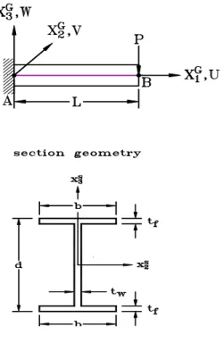
(1) A fixed global set of coordinates, XiG
(i = 1, 2, 3) (see Fig. 1).
(2) Element cross section coordinates, xiS
(i = 1, 2, 3) (see Fig. 1).
(3) Element coordinates; xi (i = 1, 2, 3)
(see Fig. 1).
(4) Load base coordinates, XiP (i = 1, 2, 3).
Fig. 1. Coordinate systems.
2.3 Kinematics of beam element
Let Q (Fig. 1) be an arbitrary point in
the beam element, and P be the point
corresponding to Q on the shear center axis.
The position vector of point Q in the
undeformed and deformed configurations may be expressed as r0 = xe1 + ye2 +ze3 (1) and 3 2 1
(
)
(
)
)
(
e
e
e
r
=
x
cx
+
v
x
+
w
x
+
θ
1,xω
e
1S+
y
e
2S+
z
e
3S (2) where x xc( ) , v x( ) ,and w x( ) are the x1,x2 and x3 coordinates of point P,
respectively, in the deformed configuration,
ω ω= ( , )y z is the Saint Venant warping
function for a prismatic beam of the same
cross section, and ei and eiS (i = 1, 2, 3)
denote the unit vectors associated with the
xi and xiS axes, respectively. Note that
ei and eiS are coincident in the undeformed state.
The relation between the vectors ei and eiS (i = 1, 2, 3) in the element coordinate system
may be obtained as [6]
eiS =Rei (3) Here, the lateral deflections of the shear center axis, v x( ) and w x( ) , and the rotation about the shear center axis, θ1( )x , are
assumed to be the Hermitian polynomials of
x.
2.4 Element nodal force vector
The element nodal force corresponding to the implicit nodal parameters is obtained from the virtual work principle in the current element coordinates.
2.5 Element tangent stiffness matr ices
The element tangent stiffness matrix corresponding to the explicit nodal parameters (referred to as explicit tangent stiffness matrix) may be obtained by differentiating the element nodal force vector with respect to explicit nodal parameters.
2.6 Load stiffness matr ix
Here, the conservative moments generated by conservative force or forces (with fixed directions) are considered, and the ways for generating conservative moment and the corresponding load stiffness matrix proposed in [7] are employed and not repeated here.
2.7 Equilibr ium equations
The nonlinear equilibrium equations may be expressed by
3
where Ψ is the unbalanced force between the internal nodal force F and the external nodal force λP, where λ is the loading parameter, and P is a reference loading.
2.8 Cr iter ion of the buckling state
Here, the zero value of the tangent stiffness matrix determinant is used as the criterion of the buckling state. The tangent stiffness matrix of the structure is assembled from the element stiffness matrix and load stiffness matrix.
3 Numer ical studies
An incremental-iterative method based on the Newton-Raphson method combined with constant arc length of incremental displacement vector [6] is employed for the solution of nonlinear equilibrium equations. The bisection method of the arc length is proposed in [8] is used here to find the buckling load. In order to initiate the secondary path, at the bifurcation point a perturbation displacement proportional to the first buckling mode is added [9].
Fig. 2. Cantilever beam subjected to end force.
The example considered here is a I-shaped cantilever beam with a vertical force P
applied at the centroid of the end cross section as shown in Fig. 2. The clamped end of the beam is fully restrained against warping, and the free end is warping free. The geometrical and material properties are :
L=10m, b=0 19. m, tf =0 013. m,
d =0 613. m, tw=0 025. m, Young's modulus E=206 10× 9 N m/ 2, and Poisson’s ratioν =0 3. (Izzuddin and Smith [5]). The present results are obtained using 40 elements. The present buckling loads are PNB = 47.333 kN. The linear buckling
load [2] are 46.359 kN. The ratios of the
minor axis (out-of-plane) flexural stiffness to the major axis (in-plane) flexural stiffness are 0.018. The load-deflection curves of the present study together with the results given in the literature are shown in Fig. 3. In Fig. 3, the results of [5] are obtained by considering a small twist imperfection, which varies linearly from zero value at the support to value of 10−3 radian at the tip.
Fig. 3. Load-tip displacements for cantilever beam subjected to end force .
4 Conclusions
This paper has proposed a consistent co-rotational total Lagrangian finite element formulation and numerical procedure for the geometric nonlinear buckling and postbuckling analysis of doubly symmetrical
4
thin-walled beams with open section. The third order term of twist rate in the element nodal forces is also considered. An incremental-iterative method based on the Newton-Raphson method combined with constant arc length of incremental displacement vector is employed for the solution of nonlinear equilibrium equations. The zero value of the tangent stiffness matrix determinant of the structure is used as the criterion of the buckling state. From the numerical examples studied, it is found that the agreement between the prebuckling displacements and buckling loads of the present study and those given in the literature is very good.
5 Refer ences
[1] V.Z. Vlasov, Thin walled Elastic Beams,
2nd ed. (English translation published for U.S. Science Foundation by Israel Program for Scientific Translations, 1961).
[2] S.P. Timoshenko and J.M. Gere, Theory of Elastic Stability, 2nd ed.
McGraw-Hill, N.Y., (1963).
[3] D.O. Brush and B.O. Almroth, Buckling of Bars, Plates and shells, McGraw-Hill,
N.Y., (1975).
[4] H. Ziegler, Principles of Structural Stability, Birkhauser Verlag Basel.,
(1977).
[5] B.A. Izzuddin and D.L. Smith, Large-displacement analysis of elastoplastic thin-walled frames, part I: formulation and implementation and part II: verification and application, J. Struct.
Engrg. ASCE 122 (1996) 905-925. [6] K.M. Hsiao, Corotational total
Lagrangian formulation for three-dimensional beam element, AIAA
Journal 30 (1992) 797-804.
[7] K.M. Hsiao, R.T. Yang and W.Y. Lin, A consistent finite element formulation for linear buckling analysis of spatial beams, Comput. Methods Appl. Mech.
Engrg. 156 (1998) 259-276.
[8] K.M. Hsiao and W.Y. Lin, A co-rotational finite element formulation for buckling and postbuckling analysis of spatial beams, Comput. Methods Appl.
Mech. Engrg. (accepted) (1999).
[9] T. Matsui and O. Matsuoka, A new finite element scheme for instability analysis of thin shells, Internat. J. Numer. Meths.