國
立
交
通
大
學
資訊科學與工程研究所
碩
士
論
文
藉由對群組關聯式的第二階層快取記憶體作路預測來節省動
態讀取耗能
WP-TLB: Way Prediction for Set-Associative L2 Cache to Save
Dynamic Read Energy
研 究 生:周資敏
指導教授:單智君 教授
藉由對群組關聯式的第二階層快取記憶體作路預測來節省動態讀取耗能 WP-TLB: Way Prediction for Set-Associative L2 Cache to Save Dynamic Read Energy
研 究 生:周資敏 Student:Tzu-Min Chou
指導教授:單智君 Advisor:Jyh-Jiun Shann
國 立 交 通 大 學
資 訊 科 學 與 工 程 研 究 所
碩 士 論 文
A ThesisSubmitted to Institute of Computer Science and Engineering College of Computer Science
National Chiao Tung University in partial Fulfillment of the Requirements
for the Degree of Master
in
Computer Science
October 2008
Hsinchu, Taiwan, Republic of China
i 藉由對群組關聯式的第二階層快取記憶體作路預測來節省動態讀取耗能
學生: 周資敏
指導教授: 單智君 博士
國立交通大學資訊工程學系(研究所)碩士班
摘要
第 二 階 層 快 取 記 憶 體 (L2 cache) 一 般 都 是 設 計 成 群 組 關 聯 式 快 取 記 憶 體 (set-associative cache),且關聯度 (associativity)很高。相較於直接對映快取記 憶體 (direct-mapped cache),會花費更多的電耗及存取時間。如果我們在群組關聯式 快取記憶體中,可以預先知道需要的資料在哪一個路 (way),在只開那個路之下,耗電 及存取時間就可以與一個路同樣大小的直接對映快取記憶體差不多。在這篇文章中,我們提出了一種針對 L2 cache 作路預測 (way prediction)的設計。 藉由在延伸設計的轉譯後備緩衝區 (Translation Lookaside Buffer, TLB)中,儲存用 來存取 L2 cache 之路索引 (way index),在不失效能的前提之下,達到節省動態耗能 的主要目的,另外還能節省 L2 cache 的平均存取時間。本設計最大的特色是,無論路 預測是否正確,皆可只存取 L2 cache 的一個路,以節省讀取耗能及存取時間。亦即, 即使當錯誤的路預測發生時,也不需要再重開其他的路找尋需要的資料。 我們使用 CACTI 4.2 來評估記憶體元件耗電和存取時間,並修改 SimpleScalar 3.0 來把我們的設計加進去,然後在 SimpleScalar 上執行 SPEC 2000 得到模擬數據。在 256KB 16-way L2 cache 之中,我們可以節省 65%的動態耗電,減少 17%的 L2 快取平均存取時 間,而只造成 0.6%的靜態耗電增加,且不會有任何效能的流失。
ii
WP-TLB: Way Prediction for Set-Associative L2 Cache to Save Dynamic Read Energy
Student: Tzu-Min Chou
Advisor: Dr. Jean Jyh-Jiun Shann
Department of Computer Science and Information Engineering
College of Electrical Engineering and Computer Science
National Chiao Tung University
Abstract
An L2 cache is usually implemented as a set-associative cache, and its associativity is usually high. It is obvious that there are more energy and access latency consumed on a set-associative cache than a direct-mapped cache with the same size. If we can know the way of the required data in advance, under only activating the corresponding way, the energy con-sumption and the access latency will be close to a direct-mapped cache which has the same size as a single way of the L2 cache.
In this paper, we proposed a design for the way prediction of L2 cache. By storing way indices in extension designed TLB (we called WP-TLB), under the premise that no perfor-mance is lost, we can achieve the main goal of saving dynamic read energy and the secondary goal of reducing access latency. Most importantly, whether the way prediction is correct or not, the energy and access latency can be saved. This is because that we can guarantee that even when miss prediction of way occurs, the other ways do not need to be probed for searching the required data.
We use CACTI 4.2 to estimate energy consumption and access latency of memory com-ponents. Moreover, we run SPEC2000 benchmark in modified SimpleScalar 3.0 simulator. According to the simulation results, in the best case, the dynamic power can be saved about 65% and the average access latency of L2 cache can be reduced 17%. And the static power is just increased about 0.6%. No overall performance will lose under our design.
iii
致謝
感謝我的指導教授 單智君這兩年來對我細心的教誨,讓我由懵懂無知的門外漢, 漸漸地深入計算機架構這個領域。另外要感謝 鍾崇斌教授在計劃會議中給予的意見指 導,雖然嚴厲但非常受用。最後要感謝論文研究過程中參與討論以及不吝付出幫助的學 長姐和同學們,你們的意見使我更容易看透自己研究的缺點與需要改善的地方。 感謝主,因為有祢的寵幸,使我在研究過程中更能不怕挫折打倒。我願舉起我的心 來敬拜祢,用生命來回應祢的愛,喔!我的主,讓我單單在乎祢,盡情的敬拜祢,阿們。iv
Table of Contents
摘要 ... i Abstract ... ii 致謝 ... iii Table of Contents ... iv List of Figures ... viList of Tables ... viii
Chapter 1 Introduction ... 1
1.1 Power Consumption of an L2 Cache ... 1
1.2 Way Prediction Concept ... 3
1.3 Motivation & Objective ... 4
Chapter 2 Background and Related Work ... 6
2.1 On-chip cache system ... 6
2.2 Way Probe Organization ... 8
2.3 Predictive Sequential Associative Cache ... 9
2.4 Way-Predicting Set-Associative Cache for High Performance and Low energy Consumption ... 10
2.5 Location Cache: A Low-Power L2 Cache System ... 12
2.6 Comparisons of Related Works ... 14
Chapter 3 Design Approach ... 16
3.1 Design Strategy ... 16
3.2 Architecture Overview ... 19
3.3 Way Table Design ... 20
3.4 Case Analysis ... 26
3.5 Hardware Implementation ... 27
Chapter 4 Experimental Result ... 29
4.1 Simulation Environment ... 29
v
4.3 Benchmark Evaluation ... 34
4.4 Access Latency for L2 Cache ... 43
4.5 Discussion ... 44
Chapter 5 Conclusion and Future Work ... 46
5.1 Conclusion ... 46
5.2 Future Work ... 46
vi
List of Figures
FIGURE 1-1 POWER DISTRIBUTION OF OVERALL PROCESSOR ... 2
FIGURE 1-2 ANORMAL READ ACTIVITY OF 4-WAY SET-ASSOCIATIVE CACHE ... 2
FIGURE 1-3 READ ENERGY PER ACCESS IN A 512KB8-WAY CACHE ... 3
FIGURE 2-1 COMMON CONFIGURATIONS OF CACHE SYSTEM ... 7
FIGURE 2-2 ARCHITECTURE OF OUR CACHE SYSTEM ... 8
FIGURE 2-3 AN EXAMPLE FOR P.S.A CACHE ... 10
FIGURE 2-4 AN EXAMPLE OF W.P.S.A CACHE ... 11
FIGURE 2-5 ACTIONS WHEN MISS WAY PREDICTION ... 12
FIGURE 2-6 THE DEFINITION OF “NEXT CACHE LINE” ... 12
FIGURE 2-7 ARCHITECTURE OF LOCATION CACHE SYSTEM ... 13
FIGURE 2-8 PREDICTION RATES IN DIFFERENT ENTRIES LOCATION CACHE ... 14
FIGURE 3-1 ATLB AND THE ATTACHED WAY TABLE ... 17
FIGURE 3-2 PERFORMANCE DEGRADATION WHEN ACCESS WAY INDEX AFTER L1MISS OCCURS ... 17
FIGURE 3-3 BLOCK BUFFERING FOR WAY TABLE ... 18
FIGURE 3-4 AVERAGE BUFFER HIT RATE (SPEC2000) ... 19
FIGURE 3-5 ARCHITECTURE OVERVIEW OF OUR DESIGN ... 20
FIGURE 3-6 CONTENTS OF THE WAY TABLE ... 21
FIGURE 3-7 UTILIZATION RATES IN WAY TABLE ... 22
FIGURE 3-8 INDEXING OF THE WAY INDEX IN WAY TABLE BY USING “FIELD INDEX” ... 23
FIGURE 3-9 AN EXAMPLE OF MISS PREDICTION WAY... 25
FIGURE 3-10 AN EXAMPLE OF DYNAMIC ENERGY SAVING OF L2CACHE BY WAY PREDICTION ... 25
FIGURE 3-11 CASE ANALYSIS FOR OUR DESIGN ... 27
FIGURE 3-12 ARCHITECTURE OF WAY PREDICTION HARDWARE ... 28
FIGURE 4-1 ADDITIONAL LEAKAGE POWER OF L2 CACHE ... 33
FIGURE 4-2 NORMALIZED DYNAMIC READ ENERGY ... 34
FIGURE 4-3 STATISTICS OF L1 AND L2CACHE MISS RATES ... 35
FIGURE 4-4 STATISTICS OF L1 AND L2AVERAGE CACHE MISS RATES ... 35
FIGURE 4-5 AVERAGE L1MISS TYPE ... 35
FIGURE 4-6 WAY TABLE HIT RATE WHEN L1 IS MISS ... 36
FIGURE 4-7 AVERAGE WAY TABLE HIT RATE WHEN L1 IS MISS ... 36
FIGURE 4-8 AVERAGE WAY HIT TYPE ... 37
FIGURE 4-9 NUMBER OF WAY TABLE HITS PER WAY TABLE WRITE ... 38
FIGURE 4-10 RATIO OF DYNAMIC READ ENERGY SAVING (COMPARE TO ORIGINAL L2CACHE) ... 39
FIGURE 4-11 RATIO OF DYNAMIC READ ENERGY SAVING (COMPARE TO OVERALL CACHE) ... 39
FIGURE 4-12 DYNAMIC ENERGY SAVING OF DIFFERENT CACHE CONFIGURATIONS ... 40
vii
FIGURE 4-14 DYNAMIC ENERGY SAVED (COMPARED TO LOCATION CACHE) ... 42
FIGURE 4-15 CHIP AREA INCREASE (COMPARED TO L2CACHE) ... 43
FIGURE 4-16 PERFORMANCE ENHANCED (MEASURED BY CYCLE COUNTS)... 43
FIGURE 4-17 AVERAGE CACHE OCCUPANCY OF PREDICT ACCESSES ... 44
FIGURE 5-1 WP-TLBPLAYS AS PRE-ACTIVATION ROLE ... 47
FIGURE 5-2 PERFORMANCE DEGRADATION FOR WAKING UP L2CACHE ... 48
viii
List of Tables
TABLE 2-1 COMPARISONS OF RELATED WORKS ... 15
TABLE 3-1 TIMING OF WRITING AND UPDATING WAY TABLE ... 24
TABLE 4-1 CACHE CONFIGURATIONS ... 29
TABLE 4-2 WAY TABLE SIZE ... 30
TABLE 4-3 PARAMETERS OF MEMORY COMPONENTS FROM CACTI4.2 ... 32
TABLE 4-4 STATISTICS OF DIFFERENT WAY TABLE ENTRIES ... 40
1
Chapter 1 Introduction
Since on-chip L2 cache is bigger and bigger nowadays, low power L2 cache becomes an
important issue in the cache system design. In this thesis, we study the design of low power
L2 caches in architecture level. And our means is to save the dynamic energy of L2 caches.
The power consumption of an on-chip set-associative L2 cache is discussed in this
chap-ter. We analyze the dynamic read energy per access in set-associative cache and introduce the
basic concept of way prediction approach. Motivations and objectives are also presented here.
1.1 Power Consumption of an L2 Cache
In the nowadays desktop processor design, on-chip set-associative L2 cache is always a
necessary component. A level-2 cache can decrease cache miss rate thus enhance performance.
Properly speaking, a larger L2 cache can decrease cache miss rate more, but its power
con-sumption will also increase significantly. There are some characteristics of an L2 cache that
we concerned:
1. The associativity is high (≥ 4).
– Higher associativity means that more cache lines should be read per access. 2. Cache line size is big (≥ 64 Bytes).
– Bigger cache line means that more read energy when accessing a cache line. 3. Access frequency depends on L1 miss rate.
– The higher L1 miss rate, the more L2 cache accesses will occur, and thus energy con-sumption of the L2 cache will increase.
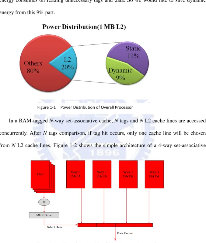
Figure 1-1 shows the power distribution of an overall processor (70 nm) [1]. The
propor-tion of 1MB L2 cache power is 20%. 11% of the processor power is the static power of the L2
cache and the other 9% part is the dynamic power. Currently, many researches focus on static
2
However, there are just few researches focus on dynamic power of L2 cache which will also
increase while the size of L2 cache is growing. And most importantly, much of dynamic
energy consumes on reading unnecessary tags and data. So we would like to save dynamic
energy from this 9% part.
In a RAM-tagged N-way set-associative cache, N tags and N L2 cache lines are accessed
concurrently. After N tags comparison, if tag hit occurs, only one cache line will be chosen
from N L2 cache lines. Figure 1-2 shows the simple architecture of a 4-way set-associative
cache. Assume that the required data is in way 2. In the conventional process, all tags and
cache lines are accessed concurrently. But, i.e., unnecessary tags and data in other ways (way
0, way1 and way 3) are read out too. Compared to a set-associative cache with sequential
Figure 1-1 Power Distribution of Overall Processor
3
search approach, this conventional process reduces the latency of accessing cache but energy
consumption will get higher.
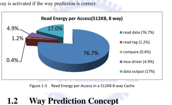
Figure 1-3 shows the read energy per access in a 512KB 8-way L2 cache which is a
common configuration in desktop processor. Reading of data and tags consumes 77.9% of
total read energy per access. Since only a single way will be the required data while the cache
is hit, 68.3% of read energy consumes on accessing unnecessary tags and data. Our research
will focus on eliminating this unnecessary read energy. To achieve this goal, a way prediction
mechanism can be applied by early identifing the way of the required data, and only a single
way is activated if the way prediction is correct.
1.2 Way Prediction Concept
The basic idea of a way prediction scheme is to make a prediction of the way where the
required data may be located in a set-associative cache. This scheme will probe the predicted
way first. Only a single way is accessed at the first probe. If the prediction is correct, access
latency and energy consumption of the cache is similar to that of a direct-mapped cache with
the same size of a single way. In the general approaches, if the first probe misses, the second
probe will access all ways expect the first probed way. In other words, if the prediction is
wrong, the cache is accessed again to retrieve the desired data, that is, the cache is accessed
twice. The performance will degrade since the access latency of the cache becomes longer.
Figure 1-3 Read Energy per Access in a 512KB 8-way Cache
76.7%
1.2%
0.4%
4.9%
17.0%
Read Energy per Access(512KB, 8 way)
read data (76.7%) read tag (1.2%) compare (0.4%) mux driver (4.9%) data output (17%)
4
1.3 Motivation & Objective
In this section, the motivations and objectives are discussed. The motivations will focus
on the benefits that past researches do not achieve. And we also introduce our design
ap-proach and goals in this section briefly.
Three motivations are showed below:
1. There is much dynamic read energy consumed on accessing unnecessary tags and cache
lines in an L2 cache (about 68% in 512KB 8-way L2 cache). If we can early identify the
way of the required data, at least 68% of dynamic read energy can be saved per access.
2. The researches of way prediction for L2 cache are few. The best power saving of L2
cache among these researches is about 47% because the prediction accuracy is not high
(70~80%). The optimal case should save 70~80% of dynamic read energy.
3. If we can guarantee that the other ways except the predicted way need not to be probed
when the way prediction is wrong, both power consumption and access latency of L2
cache can be enhanced.
Three objectives of our design are showed below:
1. Attach a table, called way table, in a translation lookaside buffer (TLB) to record the way
index of an L2 cache line when this line is placed into L2 cache. Way Index indicates the
way number in a set-associative cache. And this enhanced TLB is called way predicted
TLB (WP-TLB). The merit of attaching the way table in a TLB is that the way table need
not store and compare tags then.
2. When an address reference come to WP-TLB, the way index of the L2 cache line
asso-ciated with this address reference in the way table is searched for way prediction. If the
way table miss occurs, all tags and data are read out which is the same as a conventional
access of a set-associative cache. If the way table hit occurs, only a single way is
5
prediction is wrong, we called this situation as miss way prediction.
3. When miss way prediction occurs, make sure that miss prediction line is not in other
ways. The way index in the way table is the latest information. If the wrong way index
causes miss way prediction, it means that the corresponding L2 cache line was replaced
and has never been moved in L2 cache again. Thus only a single way must be probed
when miss way prediction occurs.
In the next chapter, we will introduce the background associated with our research more
precisely and also discuss some related researches which can be applied on L2 cache. The
de-tails of our design will be proposed in Chapter 3. And the experimental results and discussions
are showed in Chapter 4. The last chapter include conclusion of this research and future works.
And the future works will discuss static power of L2 cache and discuss our design under
6
Chapter 2 Background and Related Work
This chapter will introduce on-chip cache system more precisely, and discuss some
re-lated works of way prediction mechanisms which may be applied to the L2 cache. We also
summarize the comparisons of the related works.
2.1 On-chip cache system
In the conventional two-level cache system, L1 cache should be probed first. L2 cache
would be accessed if and only if L1 cache misses occurred. This kind of cache hierarchy will
improve overall hit rate of on-chip cache. In modern on-chip cache design, designers prefer
lower cache miss rate because cache miss penalty needs hundreds of cycles. These penalties
usually result in bad performance. Therefore, bigger caches become more and more popular
due to the necessity of higher cache hit rate. However, L1 cache size is not supposed to be
enlarged because L1 cache is usually implemented to fit the cycle time of the CPU pipeline.
Enlarging L1 cache size may cause deeper CPU pipeline or longer cycle time. The other
choice is enlarging L2 cache size. The bigger L2 cache may decrease the cache miss rate but
the dynamic and static power will increase significantly.
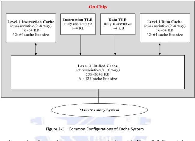
Figure 2-1 shows a general cache system architecture and the configurations of
compo-nents in the cache system. Level-1 (L1) cache which is indexed by virtual address is usually
separated into instruction cache and data cache and their size should not be too large.
Transla-tion lookaside buffer (TLB) is designed for translating virtual address to physical address.
TLB is also separated into instruction TLB and data TLB. An unified level-2 (L2) cache
which is indexed by physical address contains instructions and data. The size of L2 cache is
about 10 times bigger than L1 cache and its associativity is usually higher than eight or the
same.
The overall access latency of on-chip cache is about five or more clock cycles. However,
7
off-chip transfers is an important method for enhancing performance. A general solution is
choosing a large size and high associativity L2 cache. This kind of L2 cache can decrease
cache miss rate efficiently.
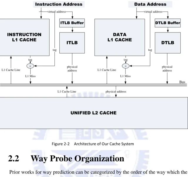
Assumption of our cache system environment is showed in Figure 2-2. Separate
instruc-tion and data L1 caches are implemented, and so are TLBs. An unified L2 cache which
con-tains instructions and data is implemented. Moreover, blocking L1 caches are implemented
[2]. Blocking cache means that when cache miss occurs, the cache will stall until the required
data are written into the cache. We also use Block Buffering technique for TLB [3]. A TLB
buffer which maintains the last accessed TLB entry is probed first. In Figure 2-2, an ITLB
buffer and a DTLB buffer are attached for ITLB and DTLB respectively.
8 INSTRUCTION L1 CACHE UNIFIED L2 CACHE ITLB Instruction Address virtual address = tag tag L1 Miss physical address ITLB Buffer DATA L1 CACHE DTLB Data Address virtual address = tag tag L1 Miss physical address DTLB Buffer L1 Cache Line
L1 Cache Line physical address L1 Cache Line
Bus
2.2 Way Probe Organization
Prior works for way prediction can be categorized by the order of the way which the
cache is probed. There are two organizations for cache probing order:
1. Statically Ordered Cache Probes
A fixed way, called the direct-mapped location, is probed first. The cache line of the
pre-dicted way should be moved to the direct-mapped location. This scheme may consume
large amount of power as well as bus bandwidth thus it is not popular in modern cache
design.
Statically ordered cache probes include the Hash-Rehash cache design [4] and the
Pseu-do-associative cache design [5] which were originally proposed to reduce the miss rates
of direct-mapped caches.
2. Dynamically Ordered Cache Probes
9
The initial probe into a cache is not limited to a fixed way, but rather to any way in the
cache. This scheme can redirect the first probe to the predicted way. No cache line
trans-fer between each way.
Most of way prediction mechanisms in current design are based on dynamically ordered
cache probes. The Predictive Sequential Associative (P.S.A) cache design [6] moves the
prediction procedure to previous stages of pipelining so that the most recently used
(MRU) information is presented to the cache simultaneously with the memory reference.
The Reactive-Associative Cache design [7] moves most active blocks to direct-mapped
positions and reactively displaces only conflicting blocks based on the PSA cache design.
The Way-Predicting Set-Associative (W.P.S.A) cache design [8] keeps the MRU
infor-mation associated to each set. The spirit of the Location Cache design [9] shows that the
next cache line which should be placed in the next set may be referenced later when
ac-cessing the current cache line.
In the next three sections, we will introduce related works of dynamically ordered cache
probes which can be applied to L2 cache.
2.3 Predictive Sequential Associative Cache
In a sequential search set-associative cache, ways are sequentially probed by an order to
find the required data. Brad Calder and et al proposed a Predictive Sequential Associative
(P.S.A) cache uses prediction sources to guide the cache examination in order to reduce the
amount of searching and thus average access latency [6]. Although this research is not for
re-ducing cache power, the design concept can be applied to reduce it.
In P.S.A cache, two data structures, the steering bit table and the rehash bits, are used to
implement predictive cache. The Steering Bit Table (SBT) determines which way in a set
should be probed first. And the rehash bits reduce the number of probes. When miss way
10
next. Figure 2-3 shows a simple 2-way P.S.A. cache architecture. The prediction sources can
be effective address, register contents and offset, and register numbers and offset. For
exam-ple, in Figure 2-3, the prediction source is partial bits of effective address, that is, 001_10.
When this cache line is referenced but not in L2 cache, the most right bit of tag bits will
de-cide which way should be placed. So the cache line with 001_10 will be placed in way 1.
However, if way 1 has already been occupied by another cache line, a rehash function will be
performed to place this cache line to another way and then set the rehash bit of the placed line
entry. In this example, the prediction source will index to entry-6 of steering bit table. And
this entry stores the information of the first probed way, i.e., way number one. If the data is
not in it, the rehash bits will indicate which way should be probed next by using rehash
func-tion. In this case, the first probe has already searched out the required data.
There are two drawbacks of P.S.A cache:
Hash collision is a big problem when the entries of steering bit table are few. This will cause the number of probes per reference getting high.
In access latency and power domains, sequential search is not proper to high associativi-ty cache. In the worst case, an N-way cache will be accessed N times.
2.4 Way-Predicting Set-Associative Cache for
11
High Performance and Low energy
Consump-tion
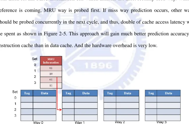
Koji Inoue and et al are proposed a Way-Predicting Set-Associative (W.P.S.A) cache for
reducing energy consumption of a set associative cache [8]. When accessing a cache set, most
recently used (MRU) block was treated as way prediction source. W.P.S.A cache proposed
MRU way prediction mechanism. It is a simple idea but the effect is pretty good.
The MRU information for each set, which is a flag, is used to speculatively choose one
way from the corresponding set. Figure 2-4 shows the basic architecture of MRU way
predic-tion. Each set has MRU information bits which indicate the most recently used way. When a
reference is coming, MRU way is probed first. If miss way prediction occurs, other ways
should be probed concurrently in the next cycle, and thus, double of cache access latency will
be spent as shown in Figure 2-5. This approach will gain much better prediction accuracy in
instruction cache than in data cache. And the hardware overhead is very low.
There are two drawbacks of W.P.S.A cache:
When miss way prediction, the other ways would be probed to find required data. Cache access latency will become longer.
L2 caches are unified caches, where most of the references come from L1 data cache
12
misses. Therefore, MRU based prediction does not always work well in L2 caches.
2.5 Location Cache: A Low-Power L2 Cache
System
Rui Min and et al proposed a location cache believes that the memory locations are
usually referenced in sequences or strides. It means that the next cache line with the same tag
may be referenced later when accessing current cache line. In Figure 2-6, the current cache
line and the next cache line are the continuous memory location. Both of these two cache lines
have the same tag and will be placed in the adjacent sets. This paper proposes to use a small
cache, called location cache, to store the location (way information) of the next cache line
when accessing the current line. And the design is for L2 cache only.
Figure 2-5 Actions When Miss Way Prediction
13
Whenever a reference to the L2 cache is generated, the way information of the next
cache line is searched in the next set and feed the way information into the location cache.
Figure 2-7 is copied from the conference paper [9]. The location cache is accessed in parallel
with the L1 caches. The tag arrays of the L2 cache are duplicated and these duplicated tag
ar-rays are called location tag arar-rays. When the L2 cache is accessed, the location tag arar-rays are
accessed to generate the way information for the next possible memory reference. The
gener-ated location information is then sent to and stored in the location cache.
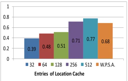
Figure 2-8 is the prediction accuracy of location caches with different numbers of entries.
It also compares the location cache to the Way-Predicting Set-Associative Cache. You can see
that if the entries of location cache are more than 256 or the same, the prediction rate will be better than W.P.S.A cache. Our approach and this research have many similarities. But some
drawbacks in this paper will be solved in our research.
There are two drawbacks of location cache:
It is the same as the W.P.S.A cache that, when miss way prediction occurs, the other ways would be probed to find the required data. Cache access latency will become
long-er.
Tag arrays of the L2 cache need to be duplicated, and thus, hardware overhead and pow-er consumption will increase.
14
2.6 Comparisons of Related Works
Table 2-1 is the comparisons of related works. The P.S.A cache and W.P.S.A cache can be
applied to both L1 and L2 caches. Location cache is design for L2 cache and thus the energy
saving of L2 cache is quite good. All of three related works need to activate other ways when
miss way prediction occurs. In the aspect of saving read energy of 512KB 8-way L2 cache,
from our simulation statistics, location cache and W.P.S.A cache can save about 50% and 30%
of dynamic read energy, respectively. Since P.S.A cache is not suitable for high associativity
cache, the energy saving of 8-way cache will be low. Compared on storage overhead issue,
based on the energy saving mentioned above, W.P.S.A cache needs the lowest 192 bytes
sto-rage and the stosto-rage overhead is fixed. The location cache needs a 1KB location cache and
8KB duplicated tag arrays. P.S.A cache needs a 4096-entry steering bit table and a rehash bit
of each line entry of L2 cache. The storage overhead is about 2KB but save the lowest read
energy of L2 cache.
0.39
0.48
0.51
0.71
0.77
0.68
0
0.2
0.4
0.6
0.8
1
Entries of Location Cache
32
64
128
256
512
W.P.S.A.
15
To give a simple abstract of our approach, we focus on saving dynamic read energy on L2
cache. In our design, the other ways do not need to be probed when miss way prediction
oc-curs. We achieve high read energy saving of L2 cache and the storage overhead is acceptable.
In the next chapter, we will detailed introduce our design strategy and approach.
16
Chapter 3 Design Approach
This chapter shows our design details. In section 3.1, we introduce how to make choices
of storing way index and to reduce energy overhead of using way index. Section 3.2 is our
design architecture overview and our design specifics are showed in section 3.3. Moreover,
many cases of cache activities should be analyzed and possible hardware implementation is
proposed in section3.4 and section 3.5, respectively.
3.1 Design Strategy
In our approach, a table is designed to store the way indices of L2 cache lines when an L2
cache line is moved into L2 cache. If we use an independent table to store way indices, the
extra tag should be add for each entry. However, if attach the table in TLB, we need not to
store tag in each entry and can avoid doing the tag comparison because TLB has already done
the job. A TLB has a fixed number of slots containing page table entries, which map virtual
addresses onto physical addresses. In general, a page contains many L2 cache lines according
to the page size and the L2 cache line size. We can attach a table to store the way indices for
the L2 cache lines contained in this page. This table is called a way table and the way index is
the way number of an L2 cache line. Each way table entry needs N fields to store way indices
if the page contains N L2 cache lines. And the number of way table entries is the same as the
number of the TLB entries. More way table entries will contain more way indices. Energy
saving of different numbers of way table entries will be discussed in Section 4.3. Figure 3-1
shows the concept of modern TLB [10] and the way table. Each entry of the TLB stores a
vir-tual page number (VPN) and a physical page number (PPN) which is accessed simultaneously
with the way table. When a VPN reference comes, the corresponding PPN and way table
en-try are read out. One field of the read out way table enen-try which contains the corresponding
way index can be chosen by partial virtual address. Compared to location cache, we can use
17
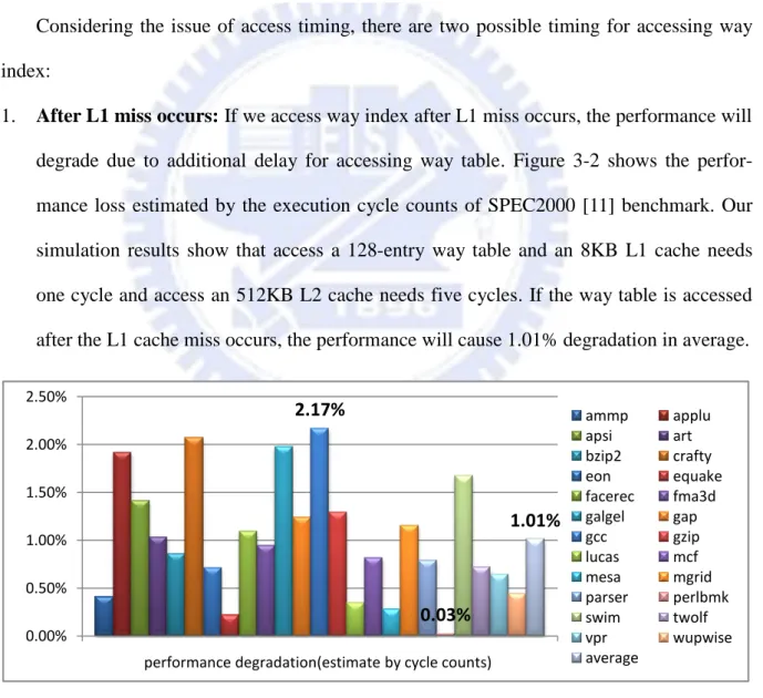
Considering the issue of access timing, there are two possible timing for accessing way
index:
1. After L1 miss occurs: If we access way index after L1 miss occurs, the performance will
degrade due to additional delay for accessing way table. Figure 3-2 shows the
perfor-mance loss estimated by the execution cycle counts of SPEC2000 [11] benchmark. Our
simulation results show that access a 128-entry way table and an 8KB L1 cache needs
one cycle and access an 512KB L2 cache needs five cycles. If the way table is accessed
after the L1 cache miss occurs, the performance will cause 1.01% degradation in average.
2. At every L1 access cycles: In this case, the time for accessing way index in a TLB may
Figure 3-1 A TLB and the Attached Way Table
2.17% 0.03% 1.01% 0.00% 0.50% 1.00% 1.50% 2.00% 2.50%
performance degradation(estimate by cycle counts)
ammp applu apsi art bzip2 crafty eon equake facerec fma3d galgel gap gcc gzip lucas mcf mesa mgrid parser perlbmk swim twolf vpr wupwise average
18
be hidden in the access latency of an L1 cache. However, it also means that we have to
access way index in every L1 access cycle even if L1 cache hit occurs.
Among the above two choices, we choose the second approach because of two reasons.
First, we do not want to suffer any performance degradation. The additional execution cycles
will waste the power of the whole chip, not just only the power of the cache system. However,
accessing the way table in every cycles is not a power efficient way. Although the second
ap-proach causes unnecessary accesses of the way table, the dynamic energy of accessing these
unnecessary way indices is much smaller than the extra static energy of a whole processor.
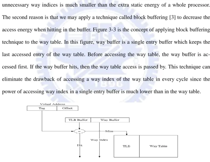
The second reason is that we may apply a technique called block buffering [3] to decrease the
access energy when hitting in the buffer. Figure 3-3 is the concept of applying block buffering
technique to the way table. In this figure, way buffer is a single entry buffer which keeps the
last accessed entry of the way table. Before accessing the way table, the way buffer is
ac-cessed first. If the way buffer hits, then the way table access is passed by. This technique can
eliminate the drawback of accessing a way index of the way table in every cycle since the
power of accessing way index in a single entry buffer is much lower than in the way table.
Figure 3-4 shows the average buffer hit rate of SPEC2000 benchmark. The hit rate of a
128-entry ITLB is 77% and the hit rate of a 128-entry DTLB is 51%. Therefore, most of the
way indices are hit in the way buffer and, hence, the way table access times decrease. The
19
overall dynamic energy of the way table also becomes lower.
3.2 Architecture Overview
Figure 3-5 shows our cache architecture. For low power goal, we record way index by
extending additional bits in TLB when an L2 cache line is moved into L2 cache. These
addi-tional bits in the TLB are called way table. We separate the way table into an instruction way
table and a data way table. The enhanced TLB is called Way Predicted TLB (WP-TLB).
Be-fore this L2 cache line is accessed again, we could search its corresponding way index in the
way table. If the way table contains the way index of this L2 cache line, then we can just
ac-tivate the predicted way of the L2 cache for saving dynamic energy.
When an L2 cache line is swapped out of the L2 cache, the corresponding way index in
the way table will not be invalidated. This action will cause miss way prediction problem.
Fortunately, in our approach, when miss way prediction occurs, the dynamic energy is also
saved because the other ways do not need to be probed to find the required cache line. This is
because that each L2 cache line has its own position in the way table, and no two different L2
cache lines will be written to the same field of a way table entry. Therefore, when miss way
prediction occurs, it means that this L2 cache line is not in the L2 cache. If this L2 cache line
is in another way, the way table must have been stored the correct way index when this L2
20
cache line is moved into one of the other ways. Based on this design approach, we do not
need to invalidate the corresponding way index in the way table when an L2 cache line is
swapped out. The complexity of the way table implementation is getting simple.
3.3 Way Table Design
Contents and utilization of a way table
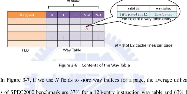
Figure 3-6 shows the proposed way table structure. The number of fields depends on
memory page size dividing by L2 cache line size. And the number of entries in a way table is
the same as the number of TLB entries. If a page contains N L2 cache lines, N fields are
at-tached to each way table entry. Each field contains a valid bit and a way index. The valid bit is
equal to one if this line’s way index has ever been recorded. All ways of the L2 cache will be
activated simultaneously while the corresponding valid bit is zero. This valid bit can
guaran-tee that we will not use the way index which has never been recorded. If no valid bit is
pro-vided in the way table, the following case will happen: when an L2 cache line was ever
rec-orded but the corresponding TLB entry was replaced, the way index of this L2 cache line will
not backup. Later a reference of this cache line comes again; the TLB will miss and then place
21
the corresponding page into a TLB entry. Because we do not have the valid bit for each way
index, so the way index will indicate an indeterminate way and may cause miss way
predic-tion. In this situation, we need to probe the other ways when miss way prediction occurs
be-cause the required data may be located in one of them. The way index is the way number of
the L2 cache line. A 4-way L2 cache means we need two bits to record.
In Figure 3-7, if we use N fields to store way indices for a page, the average utilization
fields of SPEC2000 benchmark are 37% for a 128-entry instruction way table and 63% for a
128-entry data way table. The utilization rate means that how many fields are recorded in a
way table entry. The utilization rate is the higher is the better. For a data way table, the highest
rate is 95% and the lowest rate is 6%. The gap between the highest and the lowest rate is very
large because the data use for each program is usually different. And the average rate is 63%
proves that most of N fields for a page are utilized efficiently. For an instruction way table, the
highest rate is 58% and the lowest rate is 25%. This result is caused by branch instructions.
The average rate is only 37% tells us that we can reduce half of fields per entry, for example,
two L2 cache lines share one field. Leaving the cache line competition problem aside, if the
numbers of fields are reduced by half, the additional tag need to be added in each field in
or-der to recognize different L2 cache lines. And the overall way table size with N/2 fields is
similar to a way table with N fields. The conclusion is that if we want to reduce the numbers
of fields, one-fourth of fields or fewer are better. And it may be worthy when the utilization
22
rate is less than 25%.
The relation between L2 cache lines and fields of the way table
A page would map to a physical memory block if this page resided at the memory. Figure
3-8 is an example about how a memory reference map to the dedicate field. In Figure 3-8, we
assume the virtual page 101110 maps to the physical page 1101. A memory reference 101110
0101 comes. After TLB translation, the physical address which is divided into tag, set and line
offset fields is 1101 0101. The page offset contains four bits and the line offset contains two
bits. It means that there are four L2 cache lines (A, B, C and D) in this memory page. And the
left two bits of the page offset (we called field index) would indicate the field in the way table
that we should access. In this example, the field index 01 which belongs to cache line B will
indicate to the field 1 of the corresponding way table entry. Therefore, when a memory
refer-ence comes to the way table or an L2 cache line is moved into L2 cache, we can easily access
the correct field of the way table by using its field index.
0.00% 20.00% 40.00% 60.00% 80.00% 100.00% iway dway 25.36% 6.37% 58.25% 95.43% 37.39% 63.30%
Utilization Rates in Way Table
lowest highest average
23
Writing and updating the way table
Table 3-1 shows the timing and the actions when writing and updating a way table. There
are two writing conditions. First, when an L2 cache line is moved into the L2 cache, the way
index of this line would be recorded into the way table. Second, when way table miss (valid
bit is 0) but L2 cache hit occurs, it means that the way table ever recorded the way index of
the L2 cache line but suddenly the page of this line was swapped out of the TLB, and the
cor-responding way table entry is not backup. So we must record its way index again. Besides,
when an L2 cache line is swapped out, we do not invalidate the valid bit of the corresponding
field in the way table because the overhead of searching way table for invalidating the way
index of the replaced cache line is much complicated. Moreover, avoid the invalidation of the
replaced cache line will cause miss way prediction. However, our approach will probe only a
single way when miss way prediction occurs. So the effective of no invalidation for the
re-placed cache line seems not serious. The way table needs to be updated a new way index in
one situation: when miss way prediction occurs which will be discussed briefly in the next
paragraph.
24
Figure 3-9 is an example of the miss way prediction case. Originally, line B has already
resided at way 1. After line A which comes from the main memory is moved into way 1, line
B is swapped out of L2 cache. At this moment, we do not invalidate the valid bit of line B’s
corresponding field. Later a memory reference of line B comes, and then its valid bit and the
way index of the corresponding field are 1 and 01, respectively. Only way 1 is probed at the
first access, and line A resides in it. Thus miss way prediction occurs and the way table needs
to be updated the new way index of line B. In Figure 3-9, when miss way prediction occurs, if
line B was ever moved into way 0, 2 or 3, the corresponding field would be updated the new
way index with way 0, 2 or 3 but not way 1. The field of line B holds a wrong way index
be-cause since line B was replaced by line A, line B has never been moved into the L2 cache
again. Miss way prediction tells us that line B is not in L2 cache. In fact, our approach
guar-antees that the miss predicted line is not in L2 cache. We do not need to spend extra delay for
activating the other ways of the corresponding set. The read energy is also saved when miss
way prediction occurs.
25
A basic example of saving dynamic energy
Figure 3-10 shows an example of saving the dynamic energy. Line A is an L2 cache line
and it contains four L1 cache lines, which are A0, A1, A2 and A3. When the data of A1 is
ac-cessed in the first time, A (A0, A1, A2 and A3) was moved into the L2 cache and then A1 was
moved into the L1 cache. The way index of the corresponding field of the way table was
wrote. Later the references of A0, A2 and A3 came, the way index could be found in the way
table and just activated A’s way in L2 cache. Probably, A1 was dropped out of L1 cache but A
was still in L2 cache. The memory reference of A1 could just activate a single way in L2
cache. Besides, if A is dropped out of the L2 cache but the corresponding field is not flushed
by TLB replacement, the dynamic read energy can also be saved while references of A comes.
This situation is such called miss way prediction.
Timings of just activating a single way (save dynamic energy) are summarized below:
Figure 3-9 an Example of Miss Prediction Way
26
– When references of A0, A2 or A3 come.
– A1 is dropped out of the L1 cache but A is still in the L2 cache.
– A is dropped out of the L2 cache but the valid bit of corresponding field is still be 1.
3.4 Case Analysis
In this section, we would like to analyze all cases of an L2 cache in a read procedure.
Figure 3-11 shows the flow chart of cache access activities. When L1 cache hit occurs, the L2
cache will never be accessed. The energy of the L2 cache may be saved while the L1 cache is
missed. When L1 cache miss occurs, at this moment, the TLB and the way table are already
accessed. If TLB is missed, the way table would be missed too. All ways in the L2 cache must
be activated in this case. And if TLB is hit, there are two possibilities, hit or miss, for the way
table. If the way table is hit, whether the prediction is correct or not, the dynamic read energy
is saved due to just activating a single way. And the way table needs to be updated when miss
way prediction occurs. The other possibility is that the way table miss occurs. There are two
conditions that way table would miss:
Case 1: The data was never placed into the L2 cache. So the way index has never been
rec-orded in the way table.
Case 2: The data has ever placed in the L2 cache. But this way index was flushed due to page
replacement. Suddenly this page came back to TLB and the way index which was
recorded before is not retained.
We will not save any energy but need to write the way index to the way table in these two
27
3.5 Hardware Implementation
We propose gate-level hardware architecture and high level simulation to verify our
de-sign. Figure 3-12 shows the additional hardware in our dede-sign. A way table is integrated into
the TLB to store way indices. Each way table entry contains some fields which are according
to memory page size divided by L2 cache line size. And a multiplexer is added to choose the
corresponding field by field index. After that, a valid bit and a way index are transferred to the
L2 cache decoder. The L2 cache decoder will perform a way prediction access or a normal
access which decides by the valid bit and the signal bit of L1 cache miss. We ignore the extra
control logic in L2 cache decoder because we believe the power and area which compared to
the L2 cache is much lower. In fact, the finite state machine of the extra control logic only has
few state transitions. The control signal’s overhead is also ignored for the same reason. The
energy overhead is almost consumed on the way table and the multiplexer.
28
The way table design and architecture have been proposed in this chapter. In the next
chapter, we would like to describe our design in the simulator. And also, the power
consump-tions of caches and the way table should be estimated by the power tool. At last, we will
eva-luate and analyze the simulation results briefly.
29
Chapter 4 Experimental Result
The simulation environment and the energy equation are discussed here. And also, the
statistics of simulation results will be analyzed in section 4.3. In section 4.4, we will introduce
the possibility of reducing the access latency of L2 cache.
4.1 Simulation Environment
In this section, we will estimate the power of each cache components and the overhead of
our design. The first thing that we would like to do is choosing a cache configuration for
analysis. We refer to Pentium 4 processor’s cache configuration. Table 4-1 is the cache
confi-guration that we analyze. We do not use the modern cache conficonfi-guration because the
bench-mark is SPEC2000 which was published in year 2000. The SPEC2000 is not suitable for large
cache, for example, the overall cache miss rate is only 2.40% if the L1 cache size is
16KB+16KB (a 16KB instruction cache and a 16KB data cache). Under this situation, the
memory references are almost hit in the L1 cache and thus the L2 cache seems useless.
Gen-erally, a hit rate of 90% or better is considered a normal case for an L1 cache. In an L2 cache,
a hit rate of above 50% is considered acceptable [12]. So we choose 8KB+8KB L1 caches
with 32-byte line size and associativity of two. For the L2 cache, typical size with 512 KB
30
and line size with 128 Bytes is chosen. Both 8-way and 16-way L2 caches which are in the
same size are compared. The technology node is 130nm. Our processor is single issue and
in-order execution. And the read/write port of the cache only needs one. We run the
bench-mark under all kinds of cache configurations and describe the simulation results in Section 4.3.
Moreover, we assume that the page size is 4 KB and the numbers of page are 220.
Table 4-2 shows way table sizes in different associativity L2 caches. We assume that the
TLB contains 128-enrty, therefore there is a 128-entry way table and each entry contains 32
fields. The size of a 128-entry way table will never exceed 3 KB if the associativity are
smaller than 32. The way table is like a pure SRAM which is accessed following the tag
comparison of the TLB. If TLB is hit in entry m, it will signal to way table, and thus the entry
m of way table is read out.
We use CACTI 4.2 [13] to obtain energy statistics of all cache components including the way table. Moreover, we modify SimpleScalar 3.0 [14] for our design and obtain some
statis-tics of cache activities. The overview of our simulation environments is described below:
Our processor simulator is SimpleScalar 3.0.
SimpleScalar is a cycle-based processor simulator. It can simulate the behaviors of
in-structions in each pipeline stage. So the statistics output from SimpleScalar are more
precise than instruction-based simulator.
Our benchmark is SPEC2000.
SPEC2000 is the benchmark for desktop processor. It is suitable for estimate the
31
all effects of our design. We ran one billion instructions per program. Each of the 25
programs of SPEC2000 is executed independently.
Our power tool is HP-Lab CACTI 4.2.
CACTI can measure access time, dynamic power, static power, and area of the cache.
It is a well-known power tool in the domain of low power cache design.
The processor is discussed below:
We use a traditional 5-stage pipeline with single issue and in-order execution. This
simple architecture is enough to present the energy saving of L2 cache. If we use
mul-ti-issue with out-of-order execution, the access order of the L2 cache will be changed,
but the energy saving of an L2 cache will be almost the same because the numbers of
L2 cache accesses will not change a lot. As for the caches, separate L1 caches and
TLBs are selected, and the L2 cache is unified.
We describe our design into SimpleScalar via modifying the source code of SimpleScalar.
The modification consists of the WP-TLB and its whole procedure in the processor. And then
we set the processor description including cache configurations. After that, we run SPEC2000
on the modified SimpleScalar and it will output some information that we concerned, such as
cache miss rate, way table hit rate, way buffer hit rate, etc. Moreover, we apply the
configura-tions of caches and the way table as inputs to CACTI. Then CACTI will generate the dynamic
energy of each cache component. Finally, we substitute these statistics and energy parameters
into the energy equations which will be discussed in the next section, and get the ratio of
energy saving for L2 cache due to our design.
4.2 Energy Equations
Before running the benchmark, the power equations need to be specified. There are some
con-32
cerned are showed below:
– Eset : energy of reading a set of L2
– Eway : energy of reading a single way of L2
– Ewt-read : energy of reading a way index in way table
– Ewt-write : energy of writing a way index in way table
– Ebuf : energy of accessing the way buffer
After we obtain the dynamic energy consumptions from CACTI 4.2 as mentioned above
and statistic outputs from SimpleScalar, these data can be substituted into the first three of
the following energy equations. Then these three equations can be substituted into the fourth
energy equation and thus the ratio of energy saving for an L2 cache can be calculated.
1. Total dynamic energy of original L2 cache (DEL2-ori):
Eset × no. of L2 accesses = Eset × L1 miss rate × no. of L1 accesses
2. Total dynamic energy of new L2 cache (DEL2-new):
[way hit rate × Eway + (1 – way hit rate) × Eset] × no. of L2 accesses
3. Overhead of dynamic energy (DEoverhead):
Ewt-read × no. of L1 accesses+ Ewt-write × no. of way table writes + Ebuf × no. of way buf accesses
4. Rate of dynamic energy saving:
1 - [ (DEL2-new + DEoverhead) / DEL2-ori ]
The caches and the way table configurations which are discussed in section 4.1 are the
33
inputs of CACTI 4.2 and Table 4-3 shows the outputs from CACTI 4.2. For the dynamic read
energy, an 8KB L1 cache is 7 times bigger than a 128-entry way table and 25 times smaller
than a 512KB 8-way L2 cache. [7], [8] and [9] said that "If the prediction is correct, the cache
access latency and power consumption is similar to that of a direct-mapped cache of the same
size." Hence, for the direct-mapped cache with a single way size of 512KB 8-way L2 cache,
the read energy is only 0.126 nJ. It is much smaller than the 512KB 8-way L2 cache. Besides,
if the way buffer is hit, it only consumes 0.0008 nJ in dynamic read energy. Figure 4-1 is the
additional static power of the L2 cache. It only consumes extra 0.62% static power of the
521KB 8-way L2 cache. So we believe that the additional static power can be ignored. The
normalized dynamic read energy is showed in Figure 4-2. All read energies are normalized to
the 512KB 8-way L2 cache. The way table is only 0.6% and a single way of the 8-way L2
cache is 17.7%. Compared to 512KB 16-way L2 cache, it needs 183% read energy because
two times of tags and cache lines will be read out.
0.62%
0.52%
0.45%
0.50%
0.55%
0.60%
0.65%
512KB 8-way L2
512KB 16-way L2
Additional Leakage Power (128 entries way table)
34
Now we have the power statistics and equations. In the next section, SPEC2000 will be
run in SimpleScalar under more cache configurations.
4.3 Benchmark Evaluation
In our simulation evaluation, we use the SPEC2000 benchmark to run a simulation in
SimpleScalar. Because we focus on the cache power, the processor can use uncomplicated
single issue and in-order execution pipeline with separate L1 cache and TLB. Moreover, the
L2 cache is unified. We ran one billion instructions per program. 25 programs of SPEC2000
are run. Each program was executed independently. We use two 8KB 2-way L1 caches and a
512KB 8-way L2 cache as the baseline environment.
Cache miss statistics
The cache miss rate is an important effect for power saving. If L1 cache miss rate is low,
the extra power overhead of our design will be comparative high due to less L2 cache
ac-cesses. Even the extra power overhead will exceed to the power saving of our design. Figure
4-3 is the statistics of cache miss rates. The variation of miss rates for instruction L1 caches is
very small, but for a data L1 cache and an L2 cache is big. We can observe the average cache
miss rate in Figure 4-4. The average of total L1 cache miss rate is 3.42%. This low rate is not
beneficial for our design but still saving 50% of the dynamic energy of the L2 cache. If the L1
miss rate is higher the power saving will be better. And the average of L2 cache miss rate
which is 9.95% is acceptable. Figure 4-5 shows the average L1 cache miss type. The 65% of
100.0%
17.7%
183.0%
15.9%
0.6%
0.1%
0.0%
100.0%
200.0%
L2 8-way L2 8(one) L2 16-way L2 16(one) way table way buffer
Normalized Dynamic Read Energy
35
L2 cache reads are data references. Although instruction L1 cache miss rate is only 1.58%,
there are 35% L2 cache accesses coming from L1 cache.
Way table hit rate statistics
In our approach, if the way table is hit, we can save the dynamic energy of the L2 cache
0.00% 10.00% 20.00% 30.00% 40.00% 50.00% il1.miss_rate dl1.miss_rate total_L1_miss_rate ul2.miss_rate 1.58% 8.95% 3.42% 9.95% 0.00% 2.00% 4.00% 6.00% 8.00% 10.00% 12.00%
il1.miss_rate dl1.miss_rate total_L1_miss_rate ul2.miss_rate
Average cache miss rate
35%
65%
Average L1 miss type
instruction (35%) data (65%)
Figure 4-5 Average L1 Miss Type
Figure 4-4 Statistics of L1 and L2 Average Cache Miss Rates Figure 4-3 Statistics of L1 and L2 Cache Miss Rates
36
by only activating a single way even if the prediction is wrong. So we care about the hit rate
of the way table because "way table hit" means the dynamic energy is saved. Figure 4-6
shows way table hit times divided by L1 cache miss times in instruction and data way tables.
The hit rates of data way tables for each program are unstable because the demands of data
are not always the same in different programs. In average, which is showed in Figure 4-7, the
hit rate of the instruction way table is 92.87% highly.
Figure 4-7 Average Way Table Hit Rate when L1 is Miss
The main reason is that instructions are usually reused during program execution.
Con-trast to the average hit rate of the data way table, it is 22% lower than the average hit rate of
the instruction way table. However, in Figure 4-8, the type ratio of the way table hit times is
0.00% 20.00% 40.00% 60.00% 80.00% 100.00%
iway hit rate dway hit rate
92.87% 70.04% 0.00% 20.00% 40.00% 60.00% 80.00% 100.00%
iway hit rate dway hit rate
Average way hit rate
Figure 4-6 Way Table Hit Rate when L1 is Miss37
59% for data hits. This phenomenon describes that increasing the hit rate of the data way table
is more important. The designer may try to increase the entries of the data way table. In our
simulation result, if the hit rate of the data way table increases 1%, the dynamic power saving
of a 512KB 8-way L2 cache will increase 0.85%.
Way table hit times per way table write
Figure 4-9 shows the way table hit times divided by the way table writes times. This
statistic shows that when we write a way index in the way table, how many hit times of the
way table will happen in average. The higher ratio is preferred. It can be observed that the
variation of the ratio is very big especially for instruction way tables. We think it depends on
the behavior of the program. A program executes more loops will get higher ratio. In average,
the ratio of the instruction way table is 16 and the ratio of the data one is only 2. It means that
we record the way indices of instructions in the way table is more efficient. Each way index
will be used repeatedly 16 times in average.
41%
59%
Average way hit type
iway hits (41%) dway hits (59%)
38
Dynamic read energy saving
Figure 4-10 shows the dynamic read energy saving which is compared to an original L2
cache. The highest can save 74.23% and the lowest can just save 10.04% of the dynamic read
energy of the L2 cache. We can see the average rate is 52.43%. It is not the optimum result
but still good enough. Half of dynamic read energy is saved and there is only 0.62% of the
static power increased in the L2 cache. Moreover, we would like to consider the cache system
power. Figure 4-11 is the dynamic read energy saving which is compared to the overall cache
system (L1 cache + L2 cache). Although our objective is not to save L1 cache energy, but we
need to know how much dynamic energy of the overall cache does an L2 cache occupy. The
highest can save 46.24% and the lowest can just save 2.91% of the dynamic read energy of
the overall cache. We can save 24.20% of dynamic read energy even if the whole cache
sys-tem is measured in. Comparisons of Figure 4-10 and Figure 4-11, it can be observed that
about 50% of dynamic cache read energy is consumed by the L2 cache. And greater than half
of the dynamic read energy of the L2 cache can be saved in our approach.
52060 16 37 2 0 10 1000 100000 amm p ap p lu ap si art b zip 2 crafty eo n eq u ak e facere c fma3 d galge l
gap gcc gzip lucas mcf
m es a m grid p ar se r p erlb m k sw im twolf vp r wu p wis e av era ge
Number of way table hits per way table write
iway hits / iway writes dway hits / dway writes
39
Compared to different cache configurations
Figure 4-12 is the dynamic energy saving in different kinds of cache configurations. We
choose the 256KB and 512KB L2 caches and both of them contain 8-way and 16-way
confi-gurations. The cache line size is 128 Bytes. The 1MB L2 cache is not simulated because it is
too big for the SPEC2000 benchmark. The simulation result is not impersonality due to the L2
cache hit rate is too high. In Figure 4-12, you can see the energy savings of 256KB 8-way L2 74.23% 10.04% 52.43% 0.00% 10.00% 20.00% 30.00% 40.00% 50.00% 60.00% 70.00% 80.00%
Dynamic Energy Saved(compare to original L2 cache)
ammp applu apsi art bzip2 crafty eon equake
facerec fma3d galgel gap gcc gzip lucas mcf
mesa mgrid parser swim twolf vpr wupwise average
46.24% 2.91% 24.20% 0.00% 10.00% 20.00% 30.00% 40.00% 50.00%
Dynamic Energy Saved(compare to overall cache)
ammp applu apsi art bzip2 crafty eon
equake facerec fma3d galgel gap gcc gzip
lucas mcf mesa mgrid parser perlbmk swim
twolf vpr wupwise average
Figure 4-10 Ratio of Dynamic Read Energy Saving (Compare to Original L2 Cache)
40
cache and 512KB 8-way L2 cache are almost the same. And the energy savings of 256KB
16-way L2 cache and 512KB 16-way L2 cache are almost the same, too. The 256KB and
512KB caches with the same associativity will not affect energy saving too much. However,
different associativity with the same cache size will result in different energy savings actually.
In the 256KB 16-way L2 cache, it saves the highest 65.19% of the dynamic energy of the L2
cache and the highest 37.14% of the dynamic energy of the overall cache. The energy
con-sumption of activating one of 16-way is smaller than activating one of 8-way. It is not related
to the way table hit rate or L2 cache miss rate a lot.
Comparisons of different way table entries
If the numbers of entries of the WP-TLB increase, more way indices can be recorded.
Table 4-3 shows the dynamic access energies and hit rates for the way tables with different
256KB, 128B line, 8way 256KB, 128B line, 16way 512KB, 128B line, 8way 512KB, 128B line, 16way L2 power saved 53.66% 65.19% 52.43% 62.43%
cache power saved 23.75% 37.14% 24.40% 36.39%
0.00% 10.00% 20.00% 30.00% 40.00% 50.00% 60.00% 70.00% P o we r Sa vi n g
Dynamic Energy Saving of Different Cache Configurations
Figure 4-12 Dynamic Energy Saving of Different Cache Configurations
41
entries. For a larger way table, more dynamic read energy is consumed. But the hit rate will be
improved, especially in the data way table. The hit rate of the data way table increases
signif-icantly. Figure 4-13 is the dynamic energy saving of an L2 cache in different way table entries.
Because the hit rate is improved by increasing entries, the dynamic power can be saved at
most 61.86% with a 512-entry way table. Considering the tradeoff of the hit rate and the
hardware overhead, we think an instruction way table with 128 entries and a data way table
with 512 entries are the optimum solution.
If we can just activate a single way for every accesses and have no energy overhead, the
best case of energy saving will be 82%. Our best energy saving is about 62% with a 512-entry
way table. The gap between these two ratios is 20%. There are two reasons cause this 20%
gap:
1. Our total average of the way table hit ratio is 89.2%. And the cold miss occupies 4.2%.
We need to analyze the 6.6% miss rate except the cold miss. The hit rate of the
instruc-tion way table is 93.6% and the cold miss occupies 5.7%. So we have less chance to
enhance the hit rate for an instruction way table. The hit rate of the data way table is
only 89.7% and the cold miss occupies 5.7%. Although increase the number of entries
to 1024 the hit rate will grow up to 89.7%. But a larger way table means the more
energy consumption. The energy saving of a 1024-entry way table is down to 61%.
2. If we would like to reduce the energy overhead of the way table, one solution that we
45.86%
52.43%
56.51%
61.86%
61.13%
0.00% 20.00% 40.00% 60.00% 80.00%64-entry TLB 128-entry TLB 256-entry TLB 512-entry TLB 1024-entry TLB
L2 Dynamic Power Saving for Different Way Table Entries
42
can do is to enlarge the way buffer into 2-entry. Thus more way indices will be hit in the
2-entry way buffer. But the access latency of the WP-TLB will also increase. It will be
longer than a 8KB L1 cache. So we do not consider the 2-entry way buffer if the L1
cache size is smaller than 8KB.
Our approach compares to Location Cache
We would like to compare to the location cache which achieved the best power saving of
the L2 cache among past researches. Because we do not have the detail design information of
location cache, we just get the statistics of location cache from [9] and simulate our approach
in their environment. Their environment is described in the conference paper as
fol-low:"Separate 16KB L1 instruction and L1 data caches were simulated. They are both 4-way
set-associative caches with a cache line size of 64 bytes. The unified L2 cache is a 512KB
8-way set-associative cache with the cache line size of 128 bytes. The L2 cache has 8 banks.
The bus between the L1 and L2 caches is 512-bit wide. Memory function units have 4 ports."
Figure 4-14 shows the comparisons of dynamic read energy saving between different entries
location cache and 128-entry, 256-entry WP-TLB. The 256-entry WP-TLB can save 11% read
energy more than the 512-entry location cache. Compared to the chip area, in Figure 4-15, our
WP-TLB with 256-entry increase only 1.02% chip area, but smaller location cache with
32-entry already increase 1.12% chip area.
![Figure 2-7 is copied from the conference paper [9]. The location cache is accessed in parallel with the L1 caches](https://thumb-ap.123doks.com/thumbv2/9libinfo/8709377.199900/23.892.136.777.402.697/figure-copied-conference-paper-location-accessed-parallel-caches.webp)