IEEE MICROWAVE AND WIRELESS COMPONENTS LETTERS, VOL. 19, NO. 9, SEPTEMBER 2009 551
Compact Wideband Bandpass Filters Using
Stepped-Impedance Resonators and
Interdigital Coupling Structures
Cheng-Hsien Liang and Chi-Yang Chang, Member, IEEE
Abstract—This letter proposes a microstrip 4 interdigital
stepped-impedance resonator whose impedance ratio can be very low and coupling strength between adjacent resonators can be very large. On the basis of the proposed structure, one four-pole Chebyshev and one four-pole generalized Chebyshev filter with 0.05 dB equal-ripple bandwidths of 48% and 46%, respectively, are designed and fabricated. Both implemented filters have a compact size, a wide passband, a wide upper stopband, and a high spurious passband at near 5.1 times the center frequency. Good agreement between measurements and simulations is observed.
Index Terms—Interdigital coupled lines, microstrip,
stepped-impedance resonator (SIR), wideband bandpass filter (BPF).
I. INTRODUCTION
R
ECENTLY, planar filters with the characteristics of low cost, compact size, and wide stopband play an important role in modern filter applications due to easy integration into the printed circuit board (PCB). Moreover, next generation wireless systems and high data-rate communication systems require wideband bandpass filters (BPFs). For wideband appli-cations, the conventional edge-coupled BPFs [1] require strong coupling between adjacent resonators, which requires close spacing and leads to fabrication difficulty. Broadside coupled structures [2]–[5] enable stronger coupling and filters with these structures exhibit inherently wideband characteristics. Other techniques such as three-line microstrips [6], multimode resonators [7], [8], the cascade of lowpass and highpass filters [9], and the new coupling scheme in [10] are used to design wideband BPFs. However, the above-mentioned filters may still be large in size or have a narrow upper stopband.The stepped-impedance resonator (SIR) has advantages to re-duce the circuit size and to improve the upper stopband per-formance [11]. Theoretical analysis reveals that the impedance ratio is the most important parameter character-izing the properties of the SIR, where and are the char-acteristic impedances of the high- and low-impedance sections,
Manuscript received March 16, 2009; revised May 14, 2009. First published August 11, 2009; current version published September 02, 2009. This work was supported in part by the National Science Council under Grant NSC95-2221-E-009-042-MY3, and by the Ministry of Education (MoE) under an MoE Aiming for the Top University (ATU) Plan Grant.
The authors are with the Department of Communication Engineering, National Chiao Tung University, Hsinchu 300, Taiwan (e-mail: seaman. [email protected]; [email protected]).
Color versions of one or more of the figures in this paper are available online at http://ieeexplore.ieee.org.
Digital Object Identifier 10.1109/LMWC.2009.2027060
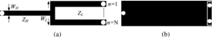
Fig. 1. Proposed SIR configuration. (a) Top view. (b) Bottom view(N = 2).
respectively. Since the SIR has a smaller size and fewer spurious modes than the SIR, it is suitable for microstrip filters. For the SIR structure, the lower the impedance ratio is, the shorter the resonator length and the farther the first spu-rious resonant frequency will be. As a result, for the conven-tional SIR with a low impedance ratio , it is difficult to obtain enough coupling for wideband BPFs.
In this letter, two compact wideband BPFs based on the pro-posed interdigital SIR are presented. By using interdigital coupled lines, strong coupling between adjacent resonators is achieved. In the meantime, the impedance ratio of the pro-posed interdigital SIR is still kept low so as to reduce the filter size and to extend the upper stopband. Furthermore, by in-troducing cross coupling between nonadjacent resonators, a pair of transmission zeros on both sides of the passband can be easily obtained to improve the selectivity of the proposed four-pole wideband BPFs.
II. FOUR-POLECHEBYSHEVFILTER
Fig. 1 shows the top and bottom layouts of the proposed interdigital SIR. Specifically, the proposed SIR consists of several parallel-connected thin strips to form the low-impedance section and a short-circuited thin strip to form the high-impedance section . Note that in Fig. 1(a), via-holes are applied on the open end of each strip in the low-impedance sec-tion where these via-holes are connected through a thin strip on the bottom layer, as shown in Fig. 1(b). This structure enables the resonator to maintain the low impedance ratio and to have better spurious response. Due to the slots in the low-impedance section of the proposed SIR, the impedance ratio is slightly larger than that of the conventional microstrip SIR without slots. The proposed four-pole filter I is a Chebyshev filter with a passband ripple of 0.05 dB, a center frequency of 1.0102 GHz, and a fractional bandwidth of 48%. The first spu-rious frequency is set more than . Filter I was fabricated on a Rogers RO4003 substrate with a relative dielectric constant of 3.58, a loss tangent of 0.0027, and a thickness of 0.508 mm. According to the specifications, the filter is implemented using the design procedures based on the coupling coefficient and
552 IEEE MICROWAVE AND WIRELESS COMPONENTS LETTERS, VOL. 19, NO. 9, SEPTEMBER 2009
Fig. 2. Configuration of the proposed filter I. (a) Top-layer layout. (b) Bottom-layer layout. Filter dimensions:L = 11:9; L = 14:45; L = 13:525; L = 12:5; L = 3:25; W = W = 0:25; W = 3:45; W = 1:05, andS = d = 0:15 mm.
the external quality factor [1]. Here,
, and . The full-wave EM software Sonnet is employed in the simulation. The closed box in Sonnet is set large enough so that it has little effect on the measured data in the open environment.
Fig. 2 depicts the top and bottom layouts of filter I. Here, we number these four resonators as 1 to 4 from left to right. Each SIR is folded in order to apply the electric or magnetic cou-pling and to reduce the filter size. As shown in Fig. 2(a), the par-allel-connected thin strips in the low-impedance section of the SIR are interdigitally coupled to the adjacent SIR. This forms a strong capacitive coupling between resonators 1 and 2 as well as 3 and 4. The coupling strength is determined by the gap width , the strip width , the number of parallel-connected strips, and the interleave length . By adjusting these parameters, various degrees of coupling between adjacent SIRs can be ob-tained. The strong coupling between resonators 2 and 3 is re-alized by the common transmission line connected to ground. The strength of the coupling is adjusted by the length of the common short-circuited stub. In this filter configuration, the coupling is magnetic, while and are mainly electric. The tap position of the input and output feed lines is chosen to match the value for the 50- source/load impedance.
In the design process, we first fix the widths of , and , and then determine the number roughly for a given filter specification. (i.e., ) can be adjusted for the prescribed normalized spurious resonant frequency. Here, the resonator dimensions are mm,
mm, mm, mm, and .
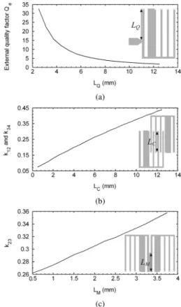
All diameters of via-holes have the same size of 0.3 mm. On the basis of the structures in Fig. 2, the design curves for the external quality factor and the coupling coefficients with
, and as parameters are shown in Fig. 3, respectively. Fig. 4 shows the fabricated filter I with a size of 11.45 mm 14.9 mm, which is , where is the guided wavelength of 50- line on the substrate at the center frequency. Fig. 5 illustrates its simulated and measured responses. The measured results show that the filter has a center frequency of 1.0105 GHz. The measured 3-dB fractional bandwidth is 64.83% from 0.7149 to 1.37 GHz. Within the passband, the minimum insertion loss is 0.63 dB, and the return loss is better than 18.9 dB. The first spurious response is at
Fig. 3. Design curves for the proposed filter I. (a) External quality factorQ . (b) Electric couplingk and k . (c) Magnetic coupling k .
Fig. 4. Top view (left side) and bottom view of the fabricated filter I.
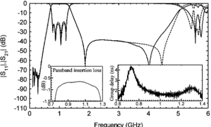
Fig. 5. Simulated (dashed line) and measured (solid line) results (jS j; jS j, and group delay) of filter I. The x-axis unit of both insets is GHz.
5.152 GHz , and the rejection level is better than dB from 1.76 to 4.357 GHz.
LIANG AND CHANG: COMPACT WIDEBAND BANDPASS FILTERS USING STEPPED-IMPEDANCE RESONATORS AND INTERDIGITAL COUPLING STRUCTURES 553
Fig. 6. Configuration of the proposed filter II. (a) Top-layer layout. (b) Bottom-layer layout. units: mm.
Fig. 7. Top view (left side) and bottom view of the fabricated filter II.
III. FOUR-POLEGENERALIZEDCHEBYSHEVFILTER
Since planar wideband Chebyshev BPFs usually have the poor upper stopband rejection, a generalized Chebyshev wideband BPF is proposed using the four-pole cross-coupled configuration. Fig. 6 depicts the top and bottom layouts of filter II. A thin microstrip line is applied at the bottom of the filter to provide the small cross coupling between resonators 1 and 4. This cross coupling produces a pair of transmission zeros on either side of the stopband. Because the cross coupling is weak, the initial design procedure is based on the fourth-order Chebyshev response filter with a 0.05 dB equal-ripple passband characteristic and follows the design process discussed above. After that, put a thin cross-coupling microstrip line and then slightly fine tune the whole filter. The proposed filter II is designed at a center frequency of 1.0079 GHz with a fractional bandwidth of 46%. Filter II was fabricated on the same substrate as filter I. Again, all the via-holes are 0.3 mm in diameter.
Fig. 7 shows the fabricated filter II with a size of
11.45 mm 14.6 mm, i.e., . The
simulated and measured responses of filter II are presented in Fig. 8. The measured results show that the filter has a center frequency of 1.0076 GHz and two transmission zeros at 0.3185 and 1.877 GHz. The measured 3-dB fractional bandwidth is 59.19% from 0.7256 to 1.322 GHz. The filter has a min-imum insertion loss of 0.64 dB and a return loss better than 19.5 dB within the passband. The first spurious frequency is at 5.159 GHz . The rejection level is better than dB from 1.542 to 4.761 GHz. Apparently, the stopband depth is largely improved compared to that of filter I.
Fig. 8. Simulated (dashed line) and measured (solid line) results (jS j; jS j, and group delay) of filter II. The x-axis unit of both insets is GHz.
IV. CONCLUSION
The proposed interdigital SIR has successfully solved the coupling strength problem of the conventional SIR. By using the proposed resonator, the BPF can have a wide pass-band and obtain a good upper stoppass-band performance. Moreover, the filter fractional bandwidth is easily varied by changing the number of interdigital strips and the interleave length. The filter with a generalized Chebyshev response can be easily achieved by applying a thin cross-coupling strip. Both of the proposed filters have a very compact size, a wide passband, and a wide upper stopband.
REFERENCES
[1] J. S. Hong and M. J. Lancaster, Microstrip Filters for RF/Microwave
Applications. New York: Wiley, 2001.
[2] M. Tran and C. Nguyen, “Modified broadside-coupled microstrip lines suitable for MIC and MMIC applications and a new class of broadside-coupled band-pass filters,” IEEE Trans. Microw. Theory Tech., vol. 41, no. 8, pp. 1336–1342, Aug. 1993.
[3] P. H. Deng, C. H. Wang, and C. H. Chen, “Novel broadside-cou-pled bandpass filters using both microstrip and coplanar-waveguide resonators,” IEEE Trans. Microw. Theory Tech., vol. 54, no. 10, pp. 3746–3750, Oct. 2006.
[4] T. N. Kuo, S. C. Lin, C. H. Wang, and C. H. Chen, “Compact bandpass filters based on dual-plane microstrip/coplanar-waveguide structure with quarter-wavelength resonators,” IEEE Microw. Wireless Compon.
Lett., vol. 17, no. 3, pp. 178–180, Mar. 2007.
[5] M. K. Mandal and S. Sanyal, “Compact wide-band bandpass filter using microstrip to slotline broadside-coupling,” IEEE Microw.
Wire-less Compon. Lett., vol. 17, no. 9, pp. 640–642, Sep. 2007.
[6] J. T. Kuo and E. Shih, “Wideband bandpass filter design with three-line microstrip structures,” Proc. Inst. Elect. Eng., vol. 149, no. 56, pp. 243–247, Oct./Dec. 2002.
[7] W. Menzel, L. Zhu, K. Wu, and F. Bogelsack, “On the design of novel compact broad-band planar filters,” IEEE Trans. Microw. Theory Tech., vol. 51, no. 2, pp. 364–370, Feb. 2003.
[8] Y. C. Chiou, J. T. Kuo, and E. Cheng, “Broadband quasi-Cheby-shev bandpass filters with multimode stepped-impedance resonators (SIRs),” IEEE Trans. Microw. Theory Tech., vol. 54, no. 8, pp. 3352–3358, Aug. 2006.
[9] C. L. Hsu, F. C. Hsu, and J. T. Kuo, “Microstrip bandpass filters for ultra-wideband (UWB) wireless communications,” in IEEE MTT-S Int.
Dig., Jun. 2005, pp. 679–682.
[10] T. N. Kuo, S. C. Lin, C. H. Wang, and C. H. Chen, “New coupling scheme for microstrip bandpass filters with quarter-wavelength res-onators,” IEEE Trans. Microw. Theory Tech., vol. 56, no. 12, pp. 2930–2935, Dec. 2008.
[11] M. Makimoto and S. Yamashita, Microwave Resonators and Filters for
Wireless Communication: Theory, Design and Application. Berlin, Germany: Springer-Verlag, 2001.