Software compensation for dispersion mismatch
in
optical
coherence tomography
Chih-Wei
Lu,
Meng-TYan Tsai, Yh-MingWang,Yean-Waei Kiang and C. C. YangGroduare hrtituie ofElecno-Optical Engineermng and Deporrmenf ofElecmcol E#gineeHng, Nononol Taiwan Uniwrsity.
1, RoosevelIRmd. Section 4;Turpei. Toiwon
Abstract: We demonstrate a novel method for dynamically and effectively compensating the fundamental and higher-order dispersion mismalches in an optical coherence tomography system based on multiple scans of sliced spectral bands and software process.
0 2003 Optical Society of America
OCIS e a l e : (170.4500) Optical coherence tomography; (170.3880) Medical and biological imaging
In a fiber-based optical coherence tomography (OCT) system, because the free space optical path in an optical Phase delay line is quite long, to match the total optical path, the fiber length in the sample arm must be longer
than
that in the reference ann. In this situation, dispersion mismatch becomes a major problem in a high-resolution OCT system. Partial dispersion compensation could be achieved by changing the length between the grating and the lens in an optical phase delay line [I]. Also. one can compensate the increasing dispersion, when scanning deeply into the sample, by rotating the grating in an optical phase delay line [21. In this paper, we demonstrate a novel dispersion compensation method, in which OCT images are first obtained with sliced light sontce spectra. Then, an appropriate combination of these images can result in a high-quality one, in which dispersion is significantly compensated. Although the repeated scanning of sliced spectrum may require a longer OCT operation time and lead to lower sensitivity, the proposed method for dispersion compensation has the advantages of flexibility and effectiveness. It is particularly useful for these OCT systems with extremely large bandwidths, in which the mirror on a galvo cannot cover the whole spectral range.In the OCT system, an SLD is used as the light source with the center wavelength at 950nm and the effective bandwidth of 4 0 m . The theoretical resolution is 9.8pm. To match the optical paths between the reference and sample arms, an about 25cm fiber length dlfference is required. The significant dispersion was partially compensated by reducing the distance between the lens and grating of the phase delay line to 9cm. With this arrangement, as shown in Fig. 1, the width of the interference fringe envelope is about 31pm. In the proposed
approach we use a
spatial filter, located between the lens and the galvanometer, for gating different wavelengthbands of the light source spectrum. The sliced spectral bands slightly overlap each other. We conduct a longitudinal scan with each spectral band. Due to dispersion, the interference fringes of different spectral bands will occur at different longitudinal positions. After properly adjusting the positions, the dispersion mismatch can be compensated by superimposing the OCT images of different scans.
Fig. 1 Interference fringe envelope with certain dispersion compensation in the optical phase delay line
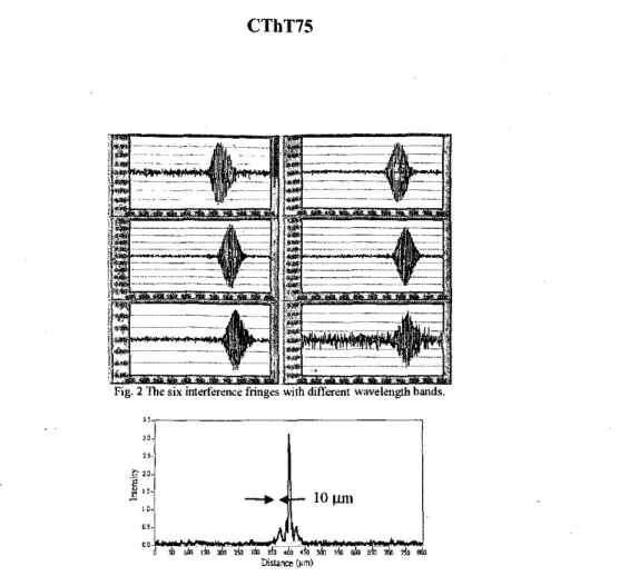
In Fig. 2, the SLY interference fringe patterns from the six longitudinal scans of a glass surface with the six successive
sliced spectral bands (16 mi in spectral width for each band) are shown. The widths of those interference fringe envelopes are all about 2 5 p q which is close to the theoretical limit. After properly shifting the positions of the six interference fringe patterns to align their envelope maximum position$ the superposition of these six fringe patterns results in resolution of about I O p , as shown in Fig. 3. Also, by properly magni$ing the fringes of the two spectral ends in Fig. 2, we can obtain a fringe of about 6 pm in envelope width, This procedure corresponds to spectral shaping, which can enhance OCT resolution at the expense of side-lobe generation.
CThT75
Fig. 3 lnterfmence h g e envelope (reduced 10 10pm) aller software process. R&rn”CW
1. W. K. Niblack, J. 0. Schenk, B. Iiu, arid hl. E. Brezinski, “Dispersion in B grating-based optical delay line for optical coherence tomography,” AppliedOpticsOT,?t, 4115-4118 (2003).
2. E. D. J. Smith, A .V. Zyagin, and D. D. Sampson, “Real-time dispersion ompensation in scanning interferometry,” Optics Letters, 21, I998 (2002).