IEEE PHOTONICS TECHNOLOGY LETTERS, VOL. 23, NO. 16, AUGUST 15, 2011 1145
The Heterostructure Photonic Crystal
Waveguide Splitter
Ting-Hang Pei and Yang-Tung Huang
Abstract—We propose a two-dimensional heterostructure pho-tonic crystal (PhC) waveguide splitter composed of different air-hole radii in the core and claddings. Two PhCs in the core and claddings are treated as two effective homogeneous media in the first photonic band. By using a triangular coupler in the input port, light can be efficiently coupled from the conventional wave-guide into the PhC wavewave-guide splitter. Total internal reflections take place at outer interfaces and confine light in the PhC wave-guide very well. Finally, incident light is divided into three parts, and each of them couples to output waveguides with total trans-mission more than 90%.
Index Terms—Heterostructure, photonic crystal (PhC), splitter.
I. INTRODUCTION
I
N integrated optical circuits, waveguide branches based on planar photonic crystals (PhCs) are an attractive developing field recently. A device which can split the input energy into two or more channels is an important application. The design of waveguide branches in the PhC with perfect transmission and zero reflection has been widely discussed [1]–[3]. They are T-shaped or Y-shaped waveguides designed to equally transport half the input energy to two output ports. The coupled mode theory is shown to explain transmission of light through these waveguides very well [3].Recently, the PhC heterostructure waveguide with 2-D tri-angular PhCs composed of air holes in a GaAs slab has been demonstrated. The waveguide is designed with the PhC core surrounded by two PhCs with smaller holes [4]. Its advantage is the large core width which can efficiently couple energy into conventional waveguides or from them. On the contrary, the PhC defect waveguide designing to support single mode is made up of such PhC removed a few lines of air holes or rods, where the core is so small that the coupling efficiency is often lower [4]–[7].
In our previous work [8], the high-transmission PhC het-erostructure Y-branch waveguide is proposed. Unlike other defect-mode PhC waveguide operating at the photonic band gap (PBG), the designed waveguide operates at photonic band region. It is composed of two different PhCs, each of them Manuscript received September 08, 2010; revised March 20, 2011; accepted April 24, 2011. Date of publication May 10, 2011; date of current version July 22, 2011. This work was supported in part by the sponsor National Science Council, Taiwan.
T.-H. Pei was with the Department of Electronics Engineering, National Chiao Tung University, Hsinchu, 300, Taiwan (e-mail: thp3000.ee88g@nctu. edu.tw).
Y.-T. Huang is with the Department of Electrionics Engineering, National Chiao Tung University, Hsinchu, 300, Taiwan (e-mail: [email protected]). Color versions of one or more of the figures in this letter are available online at http://ieeexplore.ieee.org.
Digital Object Identifier 10.1109/LPT.2011.2151278
Fig. 1. Schematic diagram of the PhC heterostructure waveguide with a tri-angular coupler connecting with a conventional waveguide. The wave is inci-dent from conventional waveguide into the PhC heterostructure waveguide. The arrow in the waveguide means the energy flow.
has different air-hole radius resulting in different effective refractive index within the first photonic band. Then these two effective media, just like the core and cladding of the conventional waveguide, confine light in the core region very efficiently. It can be explained by the mechanism of total internal reflection between two PhCs and the transverse reso-nance condition is also satisfied. This result tells us that even in complicated structures such as PhCs, the concept of effective medium still holds in certain frequency region without losing correctness of optical performances. We also propose the periodic-defect PhC and discuss its equivalent structure, the effective PhC [9], where the effective medium theory is further verified in some frequency region.
In this Letter we use the heterostructure PhC waveguide com-posed of a PhC core placing in between two PhCs to form the waveguide splitter. This structure removes the design of the T-shaped or Y-shaped waveguides and guide light into three output waveguides by the mechanism of total internal reflection at outer interfaces.
II. SIMULATEDSYSTEM
A. Structure of the PhC Heterostructure Waveguide
Consider a two-dimensional PhC heterostructure waveguide splitter lying in the - plane as shown in Fig. 1. It is composed of air holes embedded into the dielectric material with refrac-tive index in a triangular array with lattice con-stant . All the lattice concon-stants in the PhC core and claddings are the same. The elementary lattice vectors are
and , and the elementary reciprocal
lat-tice vectors in the -space are and
, respectively. The radius of air holes 1041-1135/$26.00 © 2011 IEEE
1146 IEEE PHOTONICS TECHNOLOGY LETTERS, VOL. 23, NO. 16, AUGUST 15, 2011
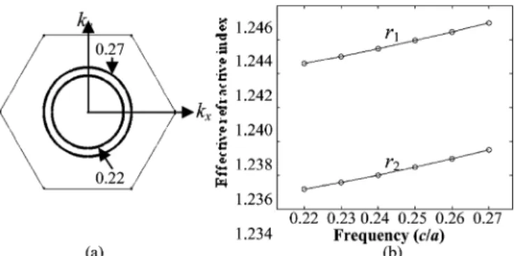
Fig. 2. (a) EFSs for . The frequencies of the inner and the outer circles are and , respectively. (b) The frequency- relations in (a) for and , respectively.
in the PhC core is and the radius in the claddings . A triangular coupler made up of the PhC, whose compo-sition is the same as the PhC core, is designed at the input port. Its purpose is to couple light efficiently from the conventional waveguide into the PhC heterostructure waveguide splitter and divide light into two parts. One is toward Interface 1 and the other is toward Interface 2. In Fig. 1, the inclined angle of the triangular coupler is 30 . The dielectric constant of the con-ventional waveguide is 1.50 and the surrounding of the wave-guide is air.
B. Effective_Refractive Index
The refracted angle of a light beam from one material into the PhC is determined by the equifrequency surfaces (EFSs) of light in the material and PhC [10]. Each EFS corresponds to certain frequency. The group velocity is normal to the EFS at a certain wave vector and defined as in which and are wave vector and frequency, respectively. Because the propaga-tion direcpropaga-tion is parallel to the group velocity, we can determine it in the PhC once is given. According to the conservation rule, the incident and refracted wave vectors are continuous for the tangential components parallel to the interface. Given the incident wave vector with frequency and the incident angle, the refracted wave vector as well as the refracted angle can be de-termined. By analyzing the EFS, we can find out the operating frequency at which optical response of the PhC is like that of a homogeneous medium.
From the EFS calculations of the first photonic band as shown in Fig. 2(a), the shapes of EFSs are round the same as those in homogeneous materials. We can define an effective refractive index from each EFS at certain frequency as shown in Fig. 2(b). The upper and lower curves are the frequency-relations corresponding to and , respectively. The radius of each EFS increases as the frequency increase, so is positive in the first photonic band [10]. The operating frequency
is chosen for studying. At this frequency, the for the PhC core is 1.2437 and that for PhC claddings is 1.2360.
The propagation wave in the infinite PhC is the Bloch wave which satisfies the periodic condition. It is sum of all the Fourier series which can be expressed as [11]
(1)
where is the wave vector in the first Brillouin zone, is a band
index, and with integers and . The
vectors are 0.2985 and 0.2966 for and , respec-tively. From our calculations at frequency , the main term for both and is the one, and both Fourier coeffi-cients in (1) are all about 99.6%. All higher ones are very small and less than 0.01 which can be ignored. It is an extremely good approximation that describes the wave in the PhC only by term in (1), which is the same as the wave in the homoge-neous medium. So the effective refractive index can reflect the optical performance of the PhC very well.
III. SIMULATIONRESULTS
A. FDTD Simulation
In order to investigate the transport phenomenon, the FDTD method [12] is used to simulate light coupling from the con-ventional waveguide to the PhC heterostructure waveguide and propagating in it. A TM-mode Gaussian wave with the elec-tric field perpendicular to the - plane is excited in the con-ventional waveguide. By using Snell’s law and the effective re-fractive indices of the PhC core and claddings, the propagation directions can be obtained. The incident wave from the conven-tional waveguide is along the direction and then incident on the triangular coupler, so the refracted angles in the triangular coupler and PhC core are both 7.09 formed with the -axis. After passing through the triangular coupler, the wave is divided into two parts and each of them propagates toward Interface 1 and Interface 2, respectively. Incident angles formed with the -axis at Interface 1 and Interface 2 are both 82.91 which is less than the critical angle 83.62 . Then one part of each wave reflects from the interface, and the other penetrates through the interface into the PhC cladding, where the propagation direction is 3.10 formed with the -axis. By further calculations, total internal reflections can take place at two outer interfaces which are between the PhC claddings and the outer media. In this case, most waves are confined in the PhC core and claddings very well. Finally, the incident wave in the conventional waveguide is divided into three parts, and then each of them enters into three output waveguides all with refractive indices . Once the propagation directions in the PhC core and claddings are ob-tained, the width and length of the waveguide in each region can be determined. In our simulation, the number of air-hole layers in the PhC core along the direction is 33, and that in each PhC cladding is 36. The width of the conventional waveguide is a little larger than the PhC core. The number of air-hole layers in the PhC core along the direction is 460. The width of the middle output waveguide is the same as the PhC core, and that of each side output waveguide is 21 air-hole layers in the direc-tion. The distribution of the electric field in the whole structure is shown in Fig. 3. It is obvious that the incident wave is split into three parts which enter three output waveguides eventually. B. Direction of Averaged Energy Velocity
Next, in order to understand the energy flow near the outer in-terface, the propagation direction of light is calculated. This pur-pose also helps to further verify the concept of effective medium in PhCs. It has been showed that the group velocity is equal
PEI AND HUANG: HETEROSTRUCTURE PHOTONIC CRYSTAL WAVEGUIDE SPLITTER 1147
Fig. 3. FDTD simulation of the wave propagating through the PhC heterostruc-ture waveguide splitter.
to the averaged energy velocity in a unit cell, that is, [13]. is defined as
(2) where is the area of a unit cell and the integral range, is the 2-D position vector, is the time-averaged Poynting vector, and is time-averaged energy density. The distribu-tion of energy direcdistribu-tions denoted in the left-upper rectangle re-gion of Fig. 3 is shown in Fig. 4, in which the arrow orientation means the direction of averaged energy velocity. From calcu-lations, all directions are almost parallel to the outer interface. The averaged propagation angle relative to the direction in this region is about 3 , which is very close to the calculation by using the effective refractive indices and Snell’s law. Further-more, the ratio of energy in three output waveguides is 1:8:1. Energy in the middle output waveguide occupies about 80% of total output energy. The transmitted efficiency from the trian-gular coupler to three output waveguides is as high as 90%.
IV. CONCLUSION
In summary, the heterostructure PhC waveguide splitter can transport light very efficiently and guide light into three output waveguides. The triangular coupler in the input port plays a role
Fig. 4. Energy flow directions near the outer interface denoted by arrows. which divides the incident light into two parts. It has been ver-ified that the effective refractive index is a very good approx-imation to treat the PhC core and claddings at the operating frequency. This structure realizing energy branches is very dif-ferent from T-shaped or Y-shaped waveguides. Unlike these de-fect PhC waveguides, the wave propagating in it obeys Snell’s law where refraction, reflection, and total internal reflection take place at interfaces. The averaged energy velocity near the outer interface indeed matches the prediction by Snell’s law. It indi-cates that varying the radius of air holes in the PhC can change the effective refractive index, which broadens the application of the PhC.
REFERENCES
[1] S. Fan, S. G. Johnson, J. D. Joannopoulos, C. Manolatou, and H. A. Haus, “Waveguide branches in photonic crystals,” J. Opt. Soc. Amer.
B, vol. 18, no. 2, pp. 162–165, Feb. 2001.
[2] S. Boscolo, M. Midrio, and T. F. Krauss, “Y junctions in photonic crystal channel waveguides: High transmission and impedance matching,” Opt. Lett., vol. 27, no. 12, pp. 1001–1003, Jun. 2002. [3] J. D. Joannopoulos, S. G. Johnson, J. N. Winn, and R. D. Meade,
Pho-tonic Crystals Molding the Flow of Light, 2nd ed. Princeton, NJ:
Princeton Univ. Press, 2008.
[4] S. Y. Lin, E. Chow, S. G. Johnson, and J. D. Joannopoulos, “Demon-stration of highly efficient waveguiding in a photonic crystal slab at the 1.5- m wavelength,” Opt. Lett., vol. 25, no. 17, pp. 1297–1299, Sep. 2000.
[5] A. Mekis, S. Fan, and J. D. Joannopoulos, “Bound states in photonic crystal waveguides and waveguide bends,” Phys. Rev. B, vol. 58, no. 8, pp. 4809–4817, Aug. 1998.
[6] Z.-Y. Li and K.-M. Ho, “Light propagation through photonic crystal waveguide bends by eigenmode examinations,” Phys. Rev. B, vol. 68, pp. 045201-1–045201-12, Jul. 2003.
[7] E. Moreno, D. Erni, and C. Hafner, “Modeling of discontinuities in photonic crystal waveguides with the multiple multipole method,”
Phys. Rev. E, vol. 66, pp. 036618-1–036618-12, Sep. 2002.
[8] T.-H. Pei and Y.-T. Huang, “The high-transmission photonic crystal heterostructure Y-branch waveguide operating at photonic band re-gion,” J. Appl. Phys., vol. 109, pp. 034504-1–034504-8, Feb. 2011. [9] T.-H. Pei and Y.-T. Huang, “The equivalent structure and some optical
properties of the periodic-defect photonic crystal,” J. Appl. Phys., vol. 109, pp. 073014-1–073014-9, Apr. 2011.
[10] M. Notomi, “Theory of light propagation in strongly modulated pho-tonic crystals: Refractionlike behavior in the vicinity of the phopho-tonic band gap,” Phys. Rev. B, vol. 62, no. 16, pp. 10 696–10 705, Oct. 2000. [11] K. Sokoda, Optical Properties of Photonic Crystals, 2nd ed. Berlin,
Germany: Springer, 2005, ch. 2.
[12] A. Taflove and S. C. Hagness, Computational Electrodynamics. Nor-wood, MA: Artech House, 2000, ch. 1–7.
[13] A. Yariv and P. Yeh, Optical Waves in Crystals. Hoboken, NJ: Wiley, 1984, ch. 6.