Short Paper
__________________________________________________Integrating Two-Dimensional Morphing
and Pose Estimation for Face Recognition
*HUI ZHEN GUAND SUH YIN LEE
Department of Computer Science and Information Engineering National Chiao Tung University
Hsinchu, 300 Taiwan
Pose problem presents a challenge to face recognition methods because the shapes and features of the human face with large pose angle often appear quite different from the template. One approach to overcome this problem involves the estimation of the an-gle to which the face is rotated and then matches it to templates with the same pose. An-other approach involves aligning the key facial features of the tested face to those of the template face before matching. However, these approaches can only achieve a moderate recognition rate, when the strict requirement of a low false alarm rate must be met. To accommodate the pose problem, this study integrates two-dimensional morphing with pose estimation. Two-dimensional morphing transforms various poses of a face image into a frontal view, thereby eliminating the center bias and pose variations and increasing the tolerance for pose estimation error. Experimental results show that two-dimensional morphing can significantly improve the performance of face recognition when dealing with severe pose variations. Combined with the pose estimation techniques, this inte-grated approach is capable of achieving very high recognition accuracy when the hori-zontal orientation is within ±45° and the vertical orientation is within ±30°. It also pro-vides acceptably good performance with a horizontal orientation up to ±75° and vertical orientation up to ±60°.
Keywords: face recognition, pose estimation, pose normalization, mirror transform,
hori-zontal morphing, vertical morphing
1. INTRODUCTION
The development of an automatic, high-performance, real-time face recognition ap- proach is a key issue in intelligent surveillance systems. Many current applications, such as access control or customized advertisements, are based on accurate face recognition [1]. Because face images are not necessarily captured in the frontal view in most real scenarios, applications must be able to recognize faces when presented with diverse pose variations.
To manage the problem of pose variation, researchers have proposed pose estima- tion approaches. Template faces comprising all horizontal and vertical viewing directions are collected. Once the pose of the tested face has been estimated, templates with the same pose are selected and the tested face is identified with the template posessing the Received November 17, 2011; revised February 29, 2012; accepted June 5, 2012.
greatest similarity [2]. Since it is difficult to estimate a facial pose with a high degree of accuracy [3] and the tested face and template may differ considerably, due to even a slight deviation in pose estimation, high-performance recognition cannot be guaranteed.
To acquire more accurate pose estimations, 3D facial modeling approaches [4, 5] have been developed. A set of parameters are estimated for shape and texture to fit a morphable model to a tested face. In [4], the Mahalanobis distance between the estimated parameters of the tested face and those of the template faces are calculated. Finally, the tested face is identified as the template with the minimum Mahalanobis distance. Since the 3D facial modeling approaches require multiple carefully placed cameras and incur heavy computation loads, they are difficult to implement in a real-time face recognition system.
If the facial features can be precisely located, pose normalization approaches [6-9] can be employed. A number of techniques, such as SIFT (Scale Invariant Feature Trans- form) [10], ASM (Active Shape Model) [11], and AAM (Active Appearance Model) [12] have been proposed to locate facial features that support the pose normalization approaches. In [6, 7], researchers calculated a transformation matrix by finding the points of correspondence between a non-frontal tested face and a frontal template face. After transforming the positions of all pixels on the tested face image using the computed matrix, a virtual frontal view face is generated from the tested face. Regarding the selection of corresponding points on face images, [6] selects the centers of both eyes, the top vertex of the brow, the left and right visor boundaries, and the bottom of the jaw. In [7], the centers of the eyes, the mouth, and the facial axis of symmetry are utilized. The transformation matrix calculation only requires 4 pairs of corresponding points.
Various methods have been proposed [10-12] to identify additional pairs of cor- responding points. When more than 4 pairs of corresponding points are acquired, a frontal image can be synthesized using texture warping [8, 9]. In [8], 62 landmark points were found manually; in [9], 72 landmark points were discovered through AAM. The disadvantages of the pose normalization methods are two-fold. First, the transformation error increases with an increase in pose difference between the tested face and the tem- plate. Because the pose angle of the template face is generally zero, the larger the rota- tion angle of the tested face, the poorer the recognition rate becomes. Second, pose normalization adjusts distinguishing features such as the distance between two eyes and the size of mouth on the tested face to make them similar to those of the template. Hence, the difference between different subjects is reduced, making it more difficult to distin- guish the identity.
In our previous paper [13], we proposed a horizontal and vertical mirror morphing scheme to alleviate the problem of poses in face recognition. The two-dimensional mirror morphing scheme normalizes the poses of the template face and the tested face into a typical frontal view. In this scheme, the correspondence is derived from the tested face and its mirror image, rather than the tested face and the template face. Thus, the dis- tinguishable features of the tested face can be maintained and higher recognition rate than previous pose normalization methods can be anticipated. However, the recognition accuracy of the scheme still drops as the rotation angle increases. In addition, the vertical morphing technique requires two cameras, placed at the top and bottom positions. If only a single camera is used, the vertical morphing procedure cannot be performed.
sional mirror morphing techniques. The main contributions of this work consist of the following:
(1) The original morphing technique in [13] provides 80% accuracy in the range of hori-zontal angle θhor [30°, 30°] and vertical angle θver [15°, 15°]. In this work, the
successful recognition range can be greatly increased to a horizontal angle of θhor
[90°, 90°] and vertical angle of θver [60°, 60°], benefit from the combination of
the morphing technique with a general pose estimation method.
(2) A single-camera vertical mirror morphing strategy is proposed to synthesize the tested face with a selected template whose view is opposite to the tested face. The strategy allows the application of two-dimensional mirror morphing in a single- camera scenario.
(3) We tested the face recognition algorithms on data captured from a large number of camera positions. According to our results, if only one camera is available, place-ment at the bottom, rather than at the top, is recommended.
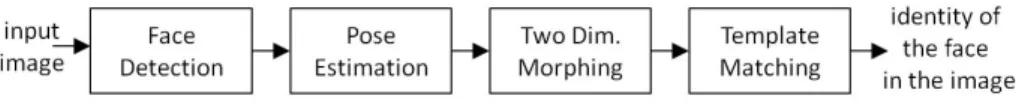
Fig. 1 presents a flowchart of the proposed system. When an image containing at least one human face is input to the system, a bounding box enclosing the face is detected. Next, pose parameters, including the locations of the facial features and the rotation an-gle of the face, are estimated. Then, both the template and the tested face poses are nor-malized horizontally and vertically. Finally, the tested face image is matched against the template face image with the same pose to acquire the identity of the face.
Fig. 1. Flowchart of the proposed system.
2. FACE DETECTION AND POSE ESTIMATION
Because locating the region of the face in an input image is essential to the effec-tiveness of face recognition applications, face detection has been the object of consider-able research. Face detection methods can be divided into three types: (1) feature-based, (2) classifier-based, and (3) skin-color-based [14]. In feature-based methods, distinct facial features, such as eyes, nose, and mouth, are detected separately and the face boundary is outlined by an ellipse. The ellipse containing the facial features is considered the detected face [15]. In classifier-based methods, a large number of face and non-face patches are collected to train a classifier, such as Adaboost [16] or support vector ma-chine [17]. When a patch is input, the classifier determines whether it belongs to a face or not. In skin-color-based methods [18, 19], a specific color or grayscale range for skin color is trained in advance. The input image is divided into several regions. A region whose pixel colors correspond most accurately to the color range is considered a face.
The color-based approach is easily implemented, efficient in computation, and ro-bust with regard to pose variations. Hence, the algorithm in [19] is adopted in the system.
When used in tandem with the PN model method proposed in [13], the locations of facial features can be approximated, and the locations are taken as the initial setting of the pose estimation step. Fig. 2 shows an input image (a) and a binary image (b). In Fig. 2 (b), the white pixels represent the pixels associated with skin and the yellow rectangle shows the skin bounding box which encloses most of the skin pixels. In Fig. 2 (c), the PN model is automatically used to scan and check the facial features within the skin bounding box. If the number of skin pixels in the positive model (painted blue) is large and the number of skin pixels in the negative model (painted red) is small, the model is fit.
(a) (b) (c)
Fig. 2. (a) Image containing a face; (b) binary image representing the pixels that belong to the skin color range; the yellow rectangle represents the bounding box enclosing the skin pixels; (c) fitting result of a positive and negative face model.
(a) (b)
Fig. 3. (a) Estimated key points of facial features; (b) Rotation angles (ver, hor) of the face.
For the accurate recognition of faces, the key points of facial features and the rota-tion angle of the face should be computed, as shown in Fig. 3. In Fig. 3 (a), the key points of the eyes, nose, mouth, and contours, which are designated by the red points and connected by the yellow lines, comprise the shape of the input face. The shape is de-scribed by the collection of all key point coordinates. This coordinate set is generally termed the shape vector sv = [(x1, y1), …, (xN, yN)], where N is the number of key points.
In Fig. 3 (b), the face pose can be characterized by pitch, roll, and yaw rotation angles. Because the roll rotation is a pure 2D transformation, the face is easily recovered. Therefore, only the pitch and yaw rotations are considered in this work. If the face look-ing at the camera is taken as (pitch, yaw) = (0°, 0°), the pitch and yaw rotations can be
seen as the vertical and horizontal rotations, respectively (i.e., ver = pitch, hor= yaw).
The PN model was able to identify the region of the face and approximate the loca-tion of the facial features in images. While the approximate localoca-tions of the detected
fa-cial features are not sufficiently accurate to support pose estimation and two-dimensional morphing, they can serve as a good initial setting for a number of key feature extraction methods, e.g. ASM [11] and AAM [12]. Because ASM is generally robust and more computationally efficient than AAM, the ASM algorithm [11] is implemented in the pro-posed system to improve the precision of facial feature extraction.
After facial features of sufficient accuracy are located by ASM, the horizontal and vertical angles (θhor, θver) of the face can be estimated. The geometric pose estimation
method [20,21], which utilizes configuration adaptation among facial features under various rotation angles, is intuitive, easily implemented, and sufficiently accurate, as long as facial features can be precisely located [3]. A geometric method [21] is implemented in the proposed system to estimate the horizontal and vertical angles.
3. TWO-DIMENSIONAL MORPHING AND TEMPLATE MATCHING
This section describes our two-dimensional (horizontal and vertical) morphing tech-nique, which is capable of transforming face images from a non-frontal view into a nor-malized frontal view. The horizontal and vertical morphing processes are introduced in Section 3.1 and Section 3.2, respectively. The vertical morphing in Section 3.2 requires two cameras located at the top and bottom. Section 3.3 provides an alternative strategy, if only a single camera is available. Template matching is introduced in Section 3.4.
3.1 Horizontal Morphing
The horizontal morphing process comprises four major steps: mirror transformation, establishing correspondence for key feature points, establishing correspondence for all pixels, and pixel prewarping. In the first step, the opposite view of the detected face F1 on an input image is acquired to recover the hidden side. Because human faces are hori-zontally symmetric, a mirror transformation is used to produce the opposite view image (F2) of the tested face (F1). For each pixel on F1 and F2, the mirror transformation can be calculated using Eq. (1). The intensity value of the pixel (x1, y1) in F1 is identical to the intensity value of the pixel (x2, y2) (= (wid(F1) x1, y1)) in F2, where wid(F1) represents the width of the detected region of the face F1:
F2 (x2, y2) = F2 (wid(F1) x1, y1) = F1 (x1, y1). (1) In the second step, the correspondence between the key feature points (x1
1, y11), …, (x1
N, y1N) extracted by ASM on F1 and the key points (x21, y21), …, (x2N, y2N) on F2 is es-tablished. If the key points on F1 are constructed as horizontally symmetric, a correspon-dence function cor describing the relationship between key point index m and its corre-sponding key point index cor(m), can be established through Eq. (2). A bi-directional arrow () represents the point correspondence relationship. For example, the center of right eye on F1 corresponds to () the center of left eye on F1.
) , , 1 1 ( ) 1 ( ) 1 m cor m cor m m y x y x ) ( ( (2)
Since F2 is produced from F1 through mirror transformation, the key point (x1cor(m),
y1
cor(m)) in F1 is transformed to the key point (x2cor(m), y2cor(m)) in F2. Hence, the key point
(x1
m, y1m) in F1 has a correspondence relationship to the key point (x2cor(m), y2cor(m)) in F2, as Eq. (3), where pixel (x2
cor(m), y2cor(m)) is in the location (wid(F1) x1cor(m), y1cor(m)).
1 1 2 2 ( ) ( ) , , m m cor m cor m x y x y ( ) ( ) (3)
In the third step, the Beier-Neely’s Field algorithm [22] is utilized to extend the cor-respondence relationship from these key points to all pixels. For the pixel (x1
i, y1i), which
is in F1 but is not one of the key points, the projection points and the distances of (x1i, y1i)
to the line segment that passes through coordinates (x1
m, y1m) and (x1n, y1n) can be
ac-quired. The correspondence pixel (x2
cor(i), y2cor(i)) in F2 should be the same distance away
from the corresponding line segment that passes through the coordinates (x2
cor(m), y2cor(m))
(= (wid(F1) x1cor(m), y1cor(m))) and (x2cor(n), y2cor(n)) (= (wid(F1)-x1cor(n), y1cor(n)) in F2. Hence, the corresponding pixel (x2
cor(i), y2cor(i)) in F2 can be computed. When multiple pairs of
line segments are considered, the weight of each line segment is determined according to the distance from (x1
i, y1i) to the line segment {(x1m, y1m), (x1n, y1n)}. The closer the pixel
to the line segment, the higher the weight is.
After the correspondence relationships for all pixels in F1 and F2 are known, the two face images can be transformed (prewarped) to the same coordinate basis in the fourth step. The new locations of each pair of corresponding pixels are generated by a weighted combination controlled by a parameter (), as given in Eq. (4). The intensity value of each pixel is interpolated using the corresponding pixel in F1 and F2 using Eq. (5). When the parameter is set at 0.5, the center of the generated face is located precisely on the center line of the synthesized image (F), and the pose of the face is normalized as frontal.
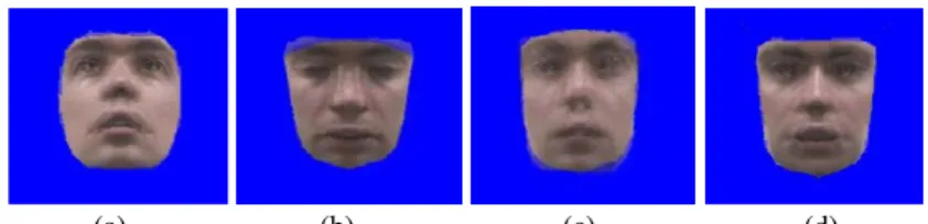
1 1 2 2 ( ) ( ) ( , ) ( , )x yi i x yi i (xcor i,ycor i ) (1 ) (4) 1 2 F , F 1, 1 F 2 , 2 1 i i i i cor(i) cor(i) x y x y x y ( ) ( ) ( ) ( ) (5) (a) (b) (c) (d) Fig. 4. Synthesized face images involved in horizontal morphing.
Fig. 4 (a) shows a non-frontal tested face with only the pixels inside the facial con-tours remaining, and Fig. 4 (b) shows its mirror image. The horizontally morphed result of these two faces is shown in Fig. 4 (c). Fig. 4 (d) shows a template image that is morphed in the same manner. The template serves as the matching reference for face recognition. By utilizing symmetry, the horizontal morphing process guarantees that the horizontal orientation of the synthesized faces will be precisely the same as the template
in horizontal frontal view, and normalizes the poses of the synthesized faces with respect to the centerline. However, the vertical orientation of the tested face and the template face are different. Therefore, the synthesized tested image and the synthesized template in Figs. 4 (c) and (d) are still not sufficiently similar.
3.2 Vertical Morphing in a Two-Camera Scenario
Since faces can be rotated horizontally and vertically, vertical morphing is also re-quired to achieve vertical pose normalization. Because human faces do not exhibit verti-cal symmetry, mirror transformations cannot be used to produce a second source image from the first source image. Hence, this study examines two different procedures: a two- camera scenario and a single-camera scenario. The single-camera procedure is discussed in Section 3.3. In the two-camera scenario, two cameras take pictures simultaneously from top and bottom viewpoints. The two face images are both normalized horizontally and then subjected to vertical morphing to generate a face that approximates a real fron-tal face.
Vertical morphing follows steps similar to those used in horizontal morphing, in-cluding establishing correspondence for key points, establishing correspondence for all pixels, and pixel prewarping only mirror transformation is omitted. First, ASM locates the facial features on the two faces captured from the top and bottom cameras (Ftop and Fbot). Next, according to the ASM results, the corresponding pairs between the key points on Ftop and Fbot are established and the morphed face can be synthesized from Ftop and Fbot
.
However, parameter in Eqs. (4) and (5) must be calculated by pose estimation, and the result is not always a fixed value of 0.5, as it is in the case of horizontal morph-ing. Because the vertical rotation angles (θtopver and θbotver) of Ftop and Fbot have been es-timated in the pose estimation step, interpolation parameter is calculated as shown in Eq. (6). bot ver top bot ver ver | sin( ) | | sin( ) | | sin( ) | (6)
The horizontal and vertical morphing procedure in a two-camera scenario is called the HVM (Horizontal and Vertical Morphing) algorithm. The input comprises two face images (Ftop, Fbot) taken from the top and bottom cameras, with the estimated vertical angles (θtop
ver, θbotver) and the shape vectors (svtop, svbot) of the two faces extracted using ASM. The algorithm will generate two horizontal pose normalized faces (hpntop, hpnbot) and one horizontal and vertical pose normalized face (hvpn). Horizontal morphing is performed on the top and bottom faces first. Then, the morphed top and bottom faces, together with their shape vectors become the input of the vertical morphing process to acquire the horizontal and vertical pose normalized face.
Fig. 5 (a), which displays the same image as Fig. 4 (c), shows a simulated face cap-tured from the bottom camera that is pose-normalized through horizontal morphing. Fig. 5 (b) shows another horizontally morphed result of the same person captured with the top camera. The vertical morphing process synthesizes Figs. 5 (a) and (b) and produces the result as shown in Fig. 5 (c). Fig. 5 (d) shows the template image used to match the tested image. Comparing Fig. 5 (c) with Fig. 5 (d), we see that most of the facial features in the
(a) (b) (c) (d)
Fig. 5. Synthesized face images produced by horizontal and vertical morphing.
tested image, including the eyes, nose, and mouth, are located at approximately the same places as the ones in the template image, although the boundary of the facial features may appear somewhat blurred. Because pose error and position bias factors are much more sensitive than the blurring phenomenon in template matching, this indicates that our two-dimensional morphing (HVM) technique is capable of making a significant con-tribution to the field of face recognition.
3.3 Vertical Morphing in a Single-Ccamera Scenario
Because HVM requires two cameras, it is not suitable if only one camera is avail-able. In a single-camera scenario, the opposite view of the tested face cannot be captured. Hence, a template stored in the dataset showing the opposite view of the tested face is selected. The vertical morphing procedure can then be applied to the tested face and the selected template face. This technique is termed the HVTM (Horizontal and Vertical Template Morphing) algorithm.
If N people are to be identified, for each subject (Si, 1 i N), a set of template images TempSet = {Ti(θhver,θkhor) | 90° θhver 90°, 60° θkhor 60°} with different horizontal and vertical poses should be prepared. If the rotation angle of the input tested face is (θh
ver, θkhor), a template with an opposite rotation angle (θhver, θkhor) is selected. Both the tested face and the selected template face are horizontally morphed, followed by vertical morphing. Because the vertical angle sum of the tested face and the selected tem-plate face should generally be zero, interpolation parameter is usually set at 0.5. Occa-sionally, a template face with a different vertical rotation angle can also be selected. In that case, interpolation parameter λ will be set according to the vertical angles of the tested face and the template face, as shown in Eq. (6).
For the HVTM algorithm, the input contains only one face image (F1), as well as the estimated angle of the face (θh
ver, θkhor), its shape vector (sv1), and the selected templates
Ti(θhver, θkhor) with its shape vector (svTih,k). After the tested face undergoes the horizon-tal morphing procedure, it is synthesized with all selected morphed templates by using the vertical morphing procedure. The outputs of the HVTM algorithm include a horizon-tally morphed face (hpn1) and several horizontally and vertically morphed faces (hvpni). 3.4 Template Matching
The morphed image of the tested face (Fig. 5 (c)) is matched against the morphed image of the template face (Fig. 5 (d)) to recognize the identity of the tested face. For each identity, the morphed template with a pose angle closest to the estimated angle of the tested face is selected from the template database. To measure the similarity of the
morphed tested face and the selected template, the sum of absolute differences (SAD) [23] between these two images is computed. The SAD value is defined as the sum of the ab-solute difference of the r, g, and b channels for each pixel between the two morphed im-ages, and averages overall pixels on the tested face image. To accommodate general lighting and weather conditions, the SAD value is calculated after the average intensity of the morphed template face is adjusting to the average intensity of the morphed tem-plate. The value is considered the feature for recognition and it is referred to as the matching error of a tested face image. If the matching error is smaller than a predefined threshold, the identity of the tested face is considered the same as that of the template face; otherwise, it is considered a different identity.
Compared the method which adopts SAD value with other advanced matching methods, such as PCA (principal component analysis) and LDA (linear discrimination analysis) [24], the SAD method does not require complex training procedures and works more efficiently. Because the variety of facial poses has been normalized through mirror morphing, the recognition accuracy of SAD is satisfactory. SAD is also faster than the normalized cross correlation (NCC) [23] matching method. Although NCC usually pro-vides slightly better accuracy than SAD, the computational load is much heavier.
4. EXPERIMENTAL RESULTS
In this section, we test the orientation range in which the proposed HVM and HVTM algorithms provide better face recognition performance. Several previous algo-rithms are implemented for comparison. Pose estimation matching (PEM) utilizes face detection, pose estimation, and template matching without any morphing. In PEM, a tested face is matched against a template face with the same pose as the estimated pose of the tested face. The Horizontal morphing and Pose Estimation Matching (HPEM) al-gorithm is similar to PEM, except that it includes horizontal morphing. In HPEM, a hori-zontally morphed template face with the same vertical pose as the tested face is selected for matching. Two additional pose normalization algorithms: Affine Transformation (AT) based on [6], and Pose Transfer and Warping (PTW) based on [8], are also included for comparison. Our results show that the HVM and HVTM algorithms can improve face recognition performance beyond what is possible using PEM, HPEM, AT, and PTW. 4.1 Dataset
The experiments employed a free face dataset the Pointing’04 dataset [25] com-prising faces with different head orientations. A head orientation consists of a pair of vertical and horizontal angles: the vertical set contains 9 angles {90°, 60°, 30°, 15°, 0°, 15°, 30°, 60°, 90°}; the horizontal set includes 13 angles {90°, 75°, 60°, 45°, -30°, 15°, 0°, 15°, 30°, 45°, 60°, 75°, 90°}. When the vertical angle is 90° or 90°, the face is looking at the floor or ceiling and the horizontal angle is 0°. In these cases, almost no facial feature can be recognized; therefore, we did not use them in our experiments. The number of rotation angles tested was (92) 13 = 91.
Moving from small to large pose angle, the images in the dataset can be classified into three pose angle areas: area1 (15° ≤ θver ≤ 15°, 45° ≤ θhor ≤ 45°); area2 (30° ≤ θver
≤ 30°, 60°≤ θhor ≤ 60°); and area3 (60°≤ θver ≤ 60°, 90° ≤ θhor ≤ 90°). The dataset in-cludes fifteen individuals; each individual contains two series of face images captured at different times. Each series has 91 different orientations with slight differences between the series, such as whether the subject is wearing glasses, and whether the expression is normal or odd. The total number of faces used in this study was 15 2 91 = 2730. Be-cause there are two series of images for each person in the dataset, one series was se-lected for training ASM, deciding pose estimation parameters, and selecting templates to match; while the other series was used for the tested images to evaluate the recognition rate.
4.2 Face Recognition Accuracy
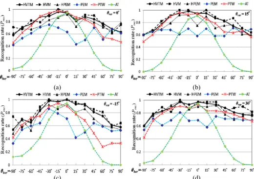
Figs. 6 (a)-(h) illustrate the recognition rates of the HVTM, HVM, HPEM, PEM, AT, and PTW algorithms on tested faces in different horizontal and vertical orientations. For a fair comparison, PTW does not employ manually annotated facial features as in [8], but utilizes landmarks that have been automatically detected using the proposed ASM implementation. The X-axis in these figures represents the horizontal rotation angle, varying from 90° to 90°. The Y-axis represents the probability of successful recognition (Prec), which is the number of tested faces of a subject Si correctly identified as Si divided by the number of tested faces of Si.
Figs. 6 (a)-(c) present the recognition rates of faces with vertical rotation angles of 0°, 15°, and 15°. These figures indicate that HVTM and HVM are superior to HPEM, and HPEM is superior to PEM for almost all horizontal rotation angles. At a horizontal rotation range of [30°, 30°], the average probabilities of successful recognition (Prec) using PEM when θver = 0°, 15°, and 15°, are 0.61, 0.63, and 0.65, respectively. For the same range of horizontal rotation: HPEM achieves recognition rates of 0.85, 0.84, and 0.87; HVM achieves recognition rates of 0.91, 0.96, 0.97; and HVTM achieves recogni-tion rates of 0.89, 0.94, and 0.96. For the AT method, the accuracy is higher than 0.8 only when the horizontal rotation angle is within [15°, 15°], dropping dramatically when the absolute value of the horizontal rotation angle increases. For the PTW method, the accuracy is higher than or close to 0.8 when the horizontal rotation angle is within [45°, 30°] and does not decrease as dramatically as AT. Comparing HVM and HVTM with PTW, we find that HVM and HVTM are comparable to PTW when the tested face is nearly frontal, and outperform PTW when the horizontal angle is greater than 30° or less than 45°.
Figs. 6 (d) and (e) show the probabilities of successful recognition (Prec) for faces with vertical rotation angles of 30° and -30°, respectively. The performances of HVTM and HVM are better with a vertical pose angle of 30° than with a vertical pose angle of 30°. If the desired probability of successful recognition (Prec) exceeds 0.8, HVTM at a vertical rotation angle of θver = 30° is adequate for a wide range of horizontal rotation angles from 60° ≤ θhor ≤ 60°. However, HVTM at θver = 30° can only achieve this goal when 30° ≤ θhor ≤ 15°. This is because facial features become less clear and more easily occluded as the face is rotated downward. This can be seen in the performance of the HVTM, HVM, HPEM, PEM, AT, and PTW algorithms, all performing less effectively in negative vertical rotation angle scenarios than in positive vertical rotation angle scenarios. The trend in recognition accuracy for PTW and AT is similar to that in Figs. 6 (a) to (c).
The recognition rate is higher when the horizontal angle is smaller, and decreases as the horizontal angle increases. According to the figures, the recognition rates of HVTM and HVM outperform PTW and AT when the vertical rotation angle is within [30°, 30°].
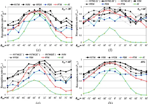
Fig. 6 (f) shows the performances of the algorithms when the vertical rotation an-gles of the faces captured by the top camera are 60°. The recognition rate of HVTM picking up the template with vertical angle 15° exceeds the recognition rate of HVTM picking up the template with vertical angle 30° or 60°. When the negative vertical an-gle of the template is smaller, the influence on recognition rate is greater. Therefore, ver-tical mirror morphing is inactivated when the estimated verver-tical orientation of the tested face is close to, or greater than 60°. Hence, HVTM can achieve the same recognition result as HPEM. HPEM was shown to be superior to PTW, PEM, and AT at all horizon-tal orientations when the vertical orientation was large.
Fig. 6 (g) shows the probability of successful recognition for faces with vertical ro-tation angles of 60°. Since the tested face has a large negative vertical angle, the recog-nition rates of HVTM, HVM, HPEM, and PEM are poorer than those with other vertical angles. For HVTM, if templates with 60° vertical angles are selected, the average recog nition rate is inferior to the performance of HVTM selecting templates with 30° or 15° vertical angle. Therefore, we selected templates with 30° and 15° vertical angles instead of those with 60°. For HVTM, working with 15° templates, the morphed image is domi-nated by the template; hence, all faces, whether they belong to the same subject or not, are transformed into similar faces. Recognizing these similar morphed images is difficult; hence, HVTM with a 30° template provides a better recognition rate than HVTM with a
(a) (b)
(c) (d)
Fig. 6. HVTM, HVM, HPEM, PEM, PTW, and AT recognition performance at varying vertical and horizontal orientations.
(e) (f)
(g) (h)
Fig. 6. (Cont’d) HVTM, HVM, HPEM, PEM, PTW, and AT recognition performance at varying vertical and horizontal orientations.
15° template in most horizontal orientations. Comparing HVTM with a 30° template to other algorithms demonstrates that HVTM is superior to PTW, PEM, and AT when the vertical orientation is 60°.
The average recognition rates of HVTM, HVM, PTW, PEM, and AT over all the vertical orientation cases in Figs. 6 (a)-(g) are shown in Fig. 6 (h). The improvements of HVTM and HTM over PTW, PEM, and AT are significant. Therefore, according to ex-perimental results, HVTM and HVM are able to provide higher recognition rates on faces under various orientations.
4.3 Orientation Coverage Range
Table 1 shows the average performances of HVTM, HVM, HPEM, PEM, AT, and PTW in different pose angle areas. PEM exhibits stable performance in all areas, and with a successful recognition rate (Prec) slightly higher than 58%. HVTM, HVM, and HPEM exhibit much better performance than PEM in all areas, and they perform better in the small pose area than in the large pose area. HVTM and HVM achieve successful recognition rates of 90.92% and 92.52% in area1, and 85.27% and 87.56% in area2, re-spectively. In area3, HVM achieved a recognition rate of 77.56%, while HVTM reached a recognition rate of 77.40%. HPEM attained moderately good recognition rates of 82.81%, 78.10%, and 71.70% in area1, area2, and area3, respectively. Thus, both HVTM and HVM cover larger ranges than HPEM. Although HVM generally has a better recogni-tion rate than HVTM, HVM requires two cameras for vertical morphing. Because HVTM
Table 1. Average performance of HVTM, HVM, HPEM, PEM, AT, and PTW in areas covering small to large pose angles.
area1 area2 area3
Algorithm 15°~15° (v) 45°~45° (h) 60° ~ 60° (h)30°~30° (v) 60°~60° (v) 90°~90° (h) HVTM 90.92% 85.27% 77.56% HVM 92.52% 87.56% 77.40% HPEM 82.81% 78.10% 71.70% PEM 63.86% 62.22% 58.32% AT 64.29% 51.48% 30.12% PTW 84.44% 77.11% 64.57% v: vertical, h: horizontal
needs only one camera, it may be a good alternative when two cameras are not available. The recognition rates of AT and PTW are shown in the last two rows of Table 1. In area1, the AT recognition rate is slightly higher than that of PEM, but less than that of HPEM. In area2 and area3, the AT recognition rate drops significantly because affine transformation cannot handle the considerable differences between faces with large pose angles and the frontal template. Better recognition accuracy than that of AT and PEM can be obtained using PTW. The PTW recognition rate is even higher than HPEM in area1, and comparable to HPEM in area2. Comparing PTW to HVM and HVTM, HVM and HVTM perform better than PTW. The improvements in recognition provided by HVM and HVTM over PTW are more significant in large vertical pose areas, because PTW is designed specifically for horizontal rotation, and is unsuitable for vertical rota-tion. In area2, HVM and HVTM show 10.45% and 8.16% improvements over PTW. In area3, HVM and HVTM improve on PTW by 12.83% and 12.99%, respectively.
4.4 Computational Load
The proposed system was implemented on an AMD AthlonⅡX2 240, 2.81GHz PC with 2.0 GB RAM under a C Language environment. The average computational time of face recognition, pose estimation, horizontal morphing, vertical morphing and template matching on a tested image of 384 288 pixels are 0.036, 0.152, 0.161, 0.161, and 0.009 sec, respectively. We assumed the number of subjects to be identified as 15. Adding the time to complete each of the steps, we found that it took HVM 0.645 (= 0.036 + 0.152 + 0.161 + 0.161 + 0.009 15) sec, and HVTM 2.899 (= 0.036 + 0.152 + 0.161 + 0.161 15 + 0.009 15) sec, to recognize a tested face image. Because the HVM approach is more efficient than HVTM, HVM can be employed in scenarios where two cameras are available. In a single camera scenario, HVTM is preferable. Different strategies can be adopted for different environments depending on factors such as the number of cameras or the efficiency of the system.
5. CONCLUSIONS
Pose problem remains a challenging issue in face recognition because the shapes and features of human faces may differ considerably from those of template faces due to
severe pose variations. This paper proposes an integrated system utilizing two-dimen- sional morphing and a pose estimation technique to manage the pose problem. In our experimental trials, conventional approaches based on pose estimation (i.e., PEM) or pose normalization (i.e., AT and PTW) were only able to achieve moderate recognition performance when the strict requirement of low false alarms had to be met. In contrast, the proposed HVTM and HVM algorithms were able to attain much better performance than the PEM, AT, and PTW algorithms under the same strict requirements.
The proposed HVTM and HVM algorithms perform well in areas covering small to large pose angles. When the horizontal rotation angle is within 60° and the vertical ro-tation angle is within 30°, the recognition rates of HVM and HVTM are greater than 87% and 85%, respectively. With a horizontal orientation up to 90° and a vertical ori-entation up to 60°, the recognition rates of both the HVM and HVTM algorithms are greater than 77%. While the recognition rate of HVM is a little higher than HVTM, it requires two cameras. If only a single camera is available, the HVTM algorithm can be employed and good recognition performance in the large orientation range can still be attained.
REFERENCES
1. B. Raducanu, J. Vitrià, and A. Leonardis, “Online pattern recognition and machine learning techniques for computer-vision: Theory and applications,” Image and
Vi-sion Computing, Vol. 28, 2010, pp. 1063-1064.
2. R. Chellappa, P. Sinha, and P. J. Phillips, “Face recognition by computers and hu-mans,” IEEE Journal of Computer Society, Vol. 43, 2010, pp. 46-55.
3. E. Murphy-Chutorian and M. M. Trivedi, “Head pose estimation in computer vision: a survey,” IEEE Transactions on Pattern Analysis and Machine Intelligence, Vol. 31, 2009, pp. 607-626.
4. V. Blanz and T. Vetter, “Face recognition based on fitting a 3D morphable model,”
IEEE Transactions on Pattern Analysis and Machine Intelligence, Vol. 25, 2003, pp.
1063-1074.
5. C. Canton-Ferrer, J. Casas, and M. Pardas, “Head pose detection based on fusion of multiple viewpoint information,” Lecture Notes in Computer Science, Vol. 4122, 2007, pp. 305-310.
6. X. Chai, S. Shan, and W. Gao, “Pose normalization for robust face recognition based on statistical affine transformation,” in Proceedings of the 4th IEEE Pacific-Rim
Conference on Multimedia, Vol. 2, 2003, pp. 1413-1417.
7. Y. Gao, M. K. H. Leung, W. Wang, and S. C. Hui, “Fast face identification under varying pose from a single 2D model view,” in Proceedings of IEE Vision Image
Signal Processing, Vol. 148, 2001, pp. 248-253.
8. D. Gonzalez-Jimenez and J. L. Alba-Castro, “Toward pose-invariant 2D face recog-nition through point distribution models and facial symmetry,” IEEE Transactions
on Information Forensics and Security, Vol. 2, 2007, pp. 413-429.
9. L. Teijeiro-Mosquera, J. L. Alba-Castro, and D. Gonzalez-Jimenez, “Face recogni-tion across pose with automatic estimarecogni-tion of pose parameters through AAM-based landmarking,” in Proceedings of International Conference on Pattern Recognition,
2010, pp. 1339-1342.
10. D. G. Lowe, “Object recognition from local scale-invariant features,” in Proceedings
of IEEE International Conference on Computer Vision, Vol. 2, 1999, pp. 1150-1157.
11. T. F. Cootes, C. J. Taylor, D. H. Cooper, and J. Graham, “Active shape models their training and application,”Computer Vision and Image Understanding, Vol. 61,
1995, pp. 38-59.
12. T. Cootes, K. Walker, and C. Taylor, “View-based active appearance models,” in
Proceedings of International Conference Automatic Face and Gesture Recognition,
2000, pp. 227-232.
13. H. Z. Gu, Y. W. Kao, S. Y. Lee, and S. M. Yuan, “HVPN: the combination of hori-zontal and vertical pose normalization for face recognition,” in Proceedings of
In-ternational Conference on Multimedia Modeling, 2009, pp. 367-378.
14. M. H. Yang, D. Kriegman, and N. Ahuja, “Detecting faces in images: a survey,”
IEEE Transactions on Pattern Analysis and Machine Intelligence, Vol. 24, 2002, pp.
34-58.
15. C. J. Huang, M. C. Ho, and C. C. Chiang, “Feature-based detection of faces in color images,” in Proceedings of International Conference on Image Processing, Vol. 3, 2004, pp. 2027-2030.
16. P. Viola and M. Jones, “Robust real-time face detection,” International Journal of
Computer Vision, Vol. 57, 2004, pp. 137-154.
17. D. Xi and S. W. Lee, “Face detection and facial feature extraction using support vec-tor machines,” in Proceedings of International Conference on Pattern Recognition, Vol. 4, 2002, pp. 209-212.
18. V. Vezhnerets, V. Sazonov, and A. Andreera, “A survey on pixel-based skin color detection technique,” in Proceedings of Graphicon, 2003, pp. 85-92.
19. S. L. Phung, A. Bouzerdoum, and D. Chai, “A novel skin color model in ycbcr color space and its application to human face detection,” in Proceedings of IEEE
Interna-tional Conference on Image Processing, Vol. 1, 2002, pp. 289-292.
20. H. Wilson, F. Wilkinson, L. Lin, and M. Castillo, “Perception of head orientation,”
Vision Research, Vol. 40, 2000, pp. 459-472.
21. A. Gee and R. Cipolla, “Determining the gaze of faces in images,” Image and Vision
Computing, Vol. 12, 1994, pp. 639-647.
22. T. Beier and S. Neely, “Feature-based image metamorphosis,” SIGGRAPH, Vol. 26, 1992, pp. 35-42.
23. R. Brunelli, Template Matching Techniques in Computer Vision: Theory and
Prac-tice, Wiley, New York, 2009.
24. A. M. Martinez and A. C. Kak, “PCA versus LDA,” IEEE Transactions on Pattern
Analysis and Machine Intelligence, Vol. 23, 2001, pp. 228-233.
25. Pointing’04, URL: http://www.prima.inrialpes.fr/pointing04/data-face.html.
Hui Zhen Gu(古蕙媜) received her MS degree in Computer Science and
Informa-tion Engineering from NaInforma-tional Chiao Tung University, Taiwan, in 2007. She is currently a Ph.D. candidate of Computer Science and Information Engineering in National Chiao Tung University. Her research interests include computer vision, content-based video re- trieval, multimedia information system, and intelligent surveillance system.
Suh Yin Lee (李素瑛) is a Professor at Computer Science and Information Engi-neering in National Chiao Tung University, Taiwan. She received her M.S. degree in Computer Science from University of Washington, Seattle, U.S.A., in 1975, and her Ph.D. degree in Computer Science from Institute of Electronics, National Chiao Tung University, Taiwan. Her research interests include content-based indexing and retrieval, distributed multimedia information system, mobile computing, and data mining.