A concentration photovoltaic system adopting a liquid crystal light
modulation
Yu-Shih Tsou
1, Yi-Hsin Lin*
,1, and An-Chi Wei
21
Department of Photonics, National Chiao Tung University,
1001 Ta Hsueh Rd., Hsinchu 30010, Taiwan, R. O. C.
2
Foxsemicon integrated technology Inc.
No.16, Kejhong Rd., Jhunan Township, Miaoli Country, Taiwan, R.O.C.
*
Corresponding author: [email protected]
ABSTRACT
A concentration photovoltaic (CPV) system adopting a liquid crystal light modulation is demonstrated. The LC light modulation adjusts the optical power density of the incident light based on the electrically controllable distribution of LC directors. The electrically tunable concentration ratio of the LC light modulation can help to achieve the highest and a fixed efficiency of the CPV system because the LC light modulation helps to increase the photocurrent at a low illumination and prevent the effect of the series resistance at a high illumination. This study opens a window in solar cells by using LC light modulations.
Keywords: Liquid crystal; liquid crystal light modulation; concentrating photovoltaic; solar cell.
1. INTRODUCTION
A solar cell is a device that converts the energy of sunlight directly into electricity by the photovoltaic effect1. In order to enhance the conversion efficiency (i.e. the ratio of output electric power to input power of light), a concentration photovoltaic (CPV) system, collecting light over a large area and then focusing the light into a small area of solar cell, is usually used2. In the CPV system, Fresnel lenses have been widely used as focusing elements to increase the number of photons entering the solar cell as well as enlarge the photocurrent density of the solar cell. When the photocurrent density is low which also causes a low output current of the solar cell, the power consumption induced by the series resistance which arises from the contact resistance, base bulk resistance, sheet resistance of the emitter, metallic resistance of the emitter and metallic resistance of the electrode can be ignored.3 However, the power consumption
induced by the series resistance cannot be ignored at a high photocurrent density. As a result, the output power of the solar cell drops dramatically and then the efficiency of the solar cell is reduced at high photocurrent density. Such an effect of the series resistance is especially sensitive to an unstable illumination condition.4-7 Because the focusing properties of the Fresnel lens is fixed, the conventional Fresnel lens used in a CPV system only provides a constant concentration ratio, which is defined as the ratio of the area (or the aperture) of the Fresnel lens to the area of the solar cell. This also means the CPV system adopting the Fresnel lens is less efficient under the various illumination conditions or the ambient sunlight. Therefore, it is important to find out solutions to improve efficiency of CPV systems. Liquid crystals (LCs) are electro-optical materials which can be used to help improving the performance of the solar cell. The anisotropic and ordering properties of LCs have been used to improve efficiency in a dye-sensitized solar cell8, the thermal properties of cholesteric LCs have been used to determine local shunts9, and a polymer solar cell has been used as the polarizer in a liquid crystal display10. Actually, the LC can also be used in modulation of an incident light, such as amplitude and phase modulations.11 On the basis of the phase modulation, electrically tunable LC lenses have been developed for years.12-16 The main mechanism of LC lenses is based on the changes of the distribution of refractive indices of a LC layer by controlling the electrically switchable orientations of LC directors, and then the phase of incident light can be modulated. This also indicates the concentration ratio of LC lenses is electrically switchable, unlike conventional Fresnel lenses. Hence, LC lenses have a great potential to replace Fresnel lenses in a CPV system in order to overcome the problem of the variation of power consumption induced by the effect of series resistance, and provide a high efficiency. In this paper, we demonstrate a CPV system adopting an electrically tunable concentration ratio of the LC light modulation by using a LC lens. We start from the operating principles and find out the relations among the efficiency of the CPV system, concentration ratio of the LC lens, and ambient illuminations. The electrically tunable concentration ratio of the LC lens can help to achieve the highest and a fixed efficiency of the CPV system because the electrically tunable concentration ratio of the LC lens helps to increase the photocurrent at a low illumination and prevent the effect of the series resistance at a high illumination. The experimental results are performed as well. We also discussed the effects of series resistance to the operating states of LC lenses. We believe this study opens a window to enhance the efficiency of CPV systems by using active optical elements.
2. OPERATING PRINCIPLES
The operating principles of the proposed CPV system adopting a LC lens are illustrated in Fig. 1(a) and Fig. 1 (b). The system consists of a LC lens, a multi-junction solar cell, andaDC-AC inverter. When the sunlight passes through a LC lens, the LC lens modulates the number of photons per area (or photon-flux density). Two layers of LCs are used in order to provide a polarization independent modulation. The photons are incident into solar cell and then are absorbed in the depletion region. When the energy of photons is larger than the diode band gap, the electron-hole pairs are excited in the depletion region, from the valence band to the conduction band, and then generate the free electrons and holes, known as the photogeneration effect. The free electrons move toward the n-type region while the holes move toward the
p-type region because of the built-in electric field of the depletion region and then the free electrons and holes form a photocurrent. The electric current (I) or directing current (DC) resulting from the drifting electrons and holes can be obtained and be converted intoan alternating current (AC) by a DC-AC inverter. Such an AC can provide electricity to other devices (such as bulbs) and the LC lens, as shown in Fig. 1(a) and Fig. 1(b). The LC lens is a device that the focusing properties change with the applied voltage due to the orientation of LC directors. Under a strong illumination in Fig. 1(a), the concentration ratio of the LC lens is controlled to be smaller by the applied voltage, which results in lower photon-flux density entering the solar cell and then reduces the effect of the series resistance. Under a weak illumination in Fig. 1(b), the concentration ratio of LC lens is adjusted to increase more photon-flux density entering the solar cell in order to enhance the output current (I). Assume that the mean photon-flux density of sunlight is φonesun and S is a sunlight factor which indicates the variation of sunlight depending on weather conditions. The photon-flux density of the incident light is S×ϕonesun before the sunlight passes through the LC lens. The number of photons actually arrived to the accepted area of the solar cell can be modulated by the LC lens. The relation between the photon-flux density from the sunlight (i. e. S×ϕonesun) and illumination accepted by the solar cell (φinput) can be expressed as:
onesun LC
input
X
V
S
ϕ
ϕ
=
(
)
×
×
, (1)where X is the concentration ratio depending on the driving voltage of the LC lens (VLC). Define a parameter XS(VLC) which is equal to S×X(VLC). XS(VLC) also indicates the total concentration ratio which is the ratio of φinput to
φonesun. The illuminated solar cell is a current source with efficiency (η), which is a ratio of the output electrical power to the power of the incident light. According to the photogeneration effect of the p-n junction, η can be expressed as:17
input OC SC h FF V J ϕ ν η × × × × = , (2)
where JSC is the short circuit current density or the photocurrent density, VOC is the open circuit voltage, FF is the fill factor, h is the Planck's constant (6.626×10⁻³⁴Joule-sec) and ν is the mean frequency of the incident light. At the low photocurrent density, the effect of the series resistance is small enough to be neglected. When XS(VLC) increases, FF remains the same, but JSC and VOC increases. As a result, η increases with the incident photon-flux density by a factor of
[
]
⎪⎭ ⎪ ⎬ ⎫ ⎪⎩ ⎪ ⎨ ⎧ ⋅ ⋅ ⋅ + ln ( ) 1 1 , LC S OC B X V V q Tk , where kB is Boltzmann's constant (1.38×10⁻²³Joule-K-1), T is temperature in Kelvin, q is the
electron charge, and VOC,1 denotes the open circuit voltage at φinput = φonesun17. At the high photocurrent density, the effect of series resistance should be considered. Assume an equivalent series resistance is RS and the power dissipation can be expressed as JSC2×RS. Thus the efficiency (η) depending on X
LC director ITO glass Solar cell
(a)
I Electrode Solar cell I I Electrode
(b)
[
]
[
] [
]
, ) ( ) ( ) ( ln 1 ) ( 2 1 , 2 1 , 1 onesun LC S S SC LC S LC S OC B LC S X V h A R J V X V X V q T k V X ϕ ν η η × × × × × × − ⎪⎭ ⎪ ⎬ ⎫ ⎪⎩ ⎪ ⎨ ⎧ × × × + × = (3)where η1 is the ideal efficiency under one sun illumination, A is the area of the solar cell, and JSC,1 denotes the short circuit current density at φinput = φonesun. When the concentration ratio of the LC lens or X(VLC) is a fixed number, not tunable, XS(VLC) is a function of sunlight factor (S). Then η changes with the sunlight factor. However, when the concentration ratio of the LC lens or X(VLC) is electrically tunable, that means X(VLC) can be adjusted by VLC and then XS(VLC) can be maintained as a constant no matter how S changes. Therefore, η can be a constant at different S.
Fig. 1 Operating principles of CPV system adopting a LC lens under (a) a strong illumination and (b) a weak illumination.
In order to obtain the highest η, we find the maximum of η
[
XS(VLC)]
. As a result, η[
XS(VLC)]
should satisfyEq.(4): 0 ) ( )] ( [ = LC S LC S V dX V X dη . (4)
According to Eq. (4), the efficiency reaches a maximum when Eq. (5) is satisfied.
A R J V q T k h V X S SC OC B onesun LC S × × × × × × × × × = 2 1 , 1 , 1 ) ( ν ϕ η . (5)
The result of the right side of Eq. (5) is a fixed number determined by the materials and the structure of the solar cell. As a result, XS(VLC) is also an invariable constant. Therefore, the LC lens with an electrically switchable concentration ratio can not only help preserving efficiency of the solar cell, but also achieve the maximum efficiency of the solar cell.
3. EXPERIMENTAL RESULTS AND DISCUSSION
To demonstrate the concept of the proposed CPV system, we adopted Sato’s structure of the LC lens and prepared two identical LC lenses.18 The structure of the LC lens consisted of two indium tin oxide (ITO) glass substrates of thickness 0.5 mm, a LC layer with a thickness of 20 μm, and mechanically buffered poly(vinyl alcohol) (PVA) layers within anti-parallel directions in order to align LC directors. One of the ITO layers was etched with a hole-pattern within a diameter of 2 mm in order to provide an inhomogeneous electric field to the LC directors. The MLC-2070 nematic LC mixture (Merck, Δn= 0.26 for λ= 589.3 nm at 20 oC) was used. Two LC lenses are stacked together with orthogonal rubbing directions in order to obtain a polarization-independent LC lens.19
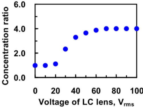
To measure the concentration ratio of the LC lens, an unpolarized He-Ne laser (Melles Griot, 8144EU for λ= 543.5 nm) was used. Instead of the solar simulator, here we used the unpolarized He-Ne laser to demonstrate the concept. The experimental trends by using the solar simulator and the laser are similar.20 The laser beam was impinged to the LC lens. We then measured the area ratio of the area of incident laser light to the area of the focused light at 25 cm behind the LC lens because the minimum focal length of the LC lens was 25 cm at VLC > 70Vrms. This area ratio is also the concentration ratio (X) of the LC lens. The concentration ratio (X) of the LC lens as a function of the applied voltage (VLC) is shown in Fig. 2. In Fig. 2, the concentration ratio increases from 1 to 4 with the applied voltage when the applied voltage is larger than threshold voltage (~ 20 Vrms). This is because the distribution of the orientations of LC directors changes with the applied voltage and then results in the smaller focusing spot. The concentration ratio saturates at 4 after VLC > 70Vrms. This is because the focal length did not change with the applied voltage as VLC > 70Vrms.Therefore, the maximum concentration ratio of the LC lens is 4.
0.0 2.0 4.0 6.0 0 20 40 60 80 100 Voltage of LC lens, Vrms C o nc en tr a tio n r at io
Fig. 2 The concentration ratio (X) of the LC lens as a function of an applied voltage (VLC).
In order to measure the efficiency of the CPV system in Fig. 1(a), the same unpolarized He-Ne laser as a light source impinged to the LC lens and then to the solar cell. The structure of the solar cell was GaInP/GaInAs/Ge triple junction (Arima, Model T3JG6F055011) with a wavelength range: 350 - 1800 nm and the diameter of 1mm. The solar cell connected a power supply (Agilent, E3631A) and a multi-meter (Agilent, 34401A) was placed 25 cm behind the LC lens.
A large area photodiode detector (New Focus, Model 2031) was used to measure irradiance of light. When we applied voltage to the LC lens, we measured the current and the voltage of the solar cell. From the current-voltage curve of the solar cell, we calculated the power of the solar cell as a function of voltage of the solar cell and then found out the maximum power of the solar cell. (The data is not shown here.) The efficiency is the maximum power of the solar cell divided by the input power of the laser light. We then plotted the efficiency as a function of the applied voltage of the LC lens, as shown in Fig. 3. We also changed the irradiance of the light source or sunlight factor (S) by using attenuators to mimic the variation of the weather condition. The S is defined as the ratio of the irradiance of the light source to the irradiance of 1 sun (~1mW/mm2). In Fig. 3 for a fixed S, at V
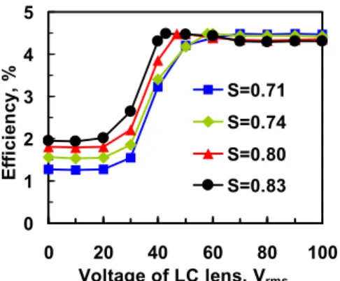
LC < Vth LC directors are not reoriented by the electric field, so the concentration ratio or incident number of photons does not change. As a result, the efficiency is unchanged. When Vth<VLC < 70 Vrms, the efficiency increases with VLC, reach a maximum and then decreases. This is because LC modulates the incident light and then the concentration ratio or incident number of photons increases with VLC. Thus, the efficiency increases as well. However, the power consumption induced by the effect of series resistance increases gradually with an increase of incident number of photons. When the power consumption induced by the effect of series resistance is large enough to compete with the output power induced by the photocurrent of the solar cell, the efficiency reaches a maximum (~4.5%) at VLC= Vmax (<70 Vrms) and then starts to decrease. When VLC> 70 Vrms, the concentration ratio or incident number of photons remain the same, the efficiency is unchanged. In addition, the efficiency increases with S as VLC< Vmax shown in Fig. 3 because of an increase of the number of photons as S increases. As a result, the efficiency varies with S even though VLC is fixed. This also means the efficiency of the solar cell under a fixed concentration ratio of LC lens (or typical case of a Fresnel lens) is not a constant, especially the condition of the ambient light changes. As to Vmax, Vmax depends on sunlight factor (S). Vmax is 43 Vrms for S=0.83, 47 Vrms for S=0.80, 58 Vrms for S=0.74, and 70 Vrms for S=0.71. In fact, the maximum efficiencies are similar~4.5% no matter what kind of sunlight condition is, as shown in Fig. 3. Therefore, according to the result of Fig. 3, we can maintain the maximum efficiency of the CPV system by adjusting VLC under different sunlight conditions.
0 1 2 3 4 5 0 20 40 60 80 100 Voltage of LC lens, Vrms Effi ci en cy , % S=0.71 S=0.74 S=0.80 S=0.83
Fig. 3 Efficiency as a function of an applied voltage of the LC lens at different S. S represents the ratio of the irradiance of the light source to the irradiance of 1 sun (~1mW/mm2).
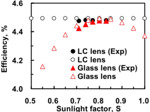
From Fig. 3, we plotted the maximum efficiency as a function of sunlight factor (black solid dots) as shown in Fig. 4. The maximum efficiency means the efficiency at Vmax in Fig. 3 for a fixed S. According to Eq. (3), we also calculated the maximum efficiency at different S after considering the experimental parameters: η1 = 4.28 %, T = 300 K, q = 1.6 × 10⁻¹⁹ C, VOC,1 = 0.5 V, JSC,1 = 24 A/m2, RS = 40 kΩ, A = 0.785 mm2, ν = 5.52 × 10¹⁴ Hz, φonesun = 2.73 × 10²¹ photons/s-m2 , XS(VLC) = 2.84.The calculated results are shown in hollow dots in Fig. 4. As we can see, the experimental results and calculated results of maximum efficiency are agreeable. In addition, the maximum efficiency is almost a constant (~ 4.5 %) independent of S. This means we can operate the CPV system at the maximum efficiency by adjusting the applied voltage of the LC lens and such efficiency does not change even though sunlight conditions changes. In comparison, we also measured the efficiency of a CPV system adopting a glass lens whose concentration ratio is fixed (X~3.5) at different S, as shown in the red solid triangles in Fig. 4. The efficiency of a CPV system adopting a glass lens changes with S, not a constant. We then calculated the maximum efficiency at different S, as shown in hollow red triangles in Fig. 4 after considering XS = 0 to 3.5 for S=0 to 1. The experimental results agree quite well with calculated results. To compare two CPV systems, the efficiency of the CPV systems using the glass lens changes with sunlight conditions; however, the efficiency of the CPV systems using the LC lens is not only invariable, but also a maximum in the whole system. Therefore, the CPV system can be utilized at the highest efficiency under all kinds of sunlight conditions by using LC lens. 4.0 4.2 4.4 4.6 0.5 0.6 0.7 0.8 0.9 1.0 Sunlight factor, S Effi ci en cy , % LC lens (Exp) LC lens
Glass lens (Exp) Glass lens
Fig. 4 The maximum efficiency as a function of the sunlight factor. Black solid dots stand for the experimental result and hollow black dots stand for calculated results in the CPV system adopting the LC lens. Red solid triangles stand for
the experimental result and hollow red triangles stand for calculated results in the CPV system adopting the glass lens.
The power consumption of the LC lens is low compared to the whole CPV system. The measured current of the LC lens was 0.19 μA and the maximum voltage of the LC lens in the CPV system was 70 Vrms. As a result, the power consumption of the LC lens is around 6.65 μW. We can also calculate the output power of CPV system. The output power of the CPV system adopting the LC lens ranged from 0 to 141 μW when S changes from 0 to 1 for the area of the LC lens of 3.14 mm2 and the efficiency of 4.5%; meanwhile, the output power of the CPV system adopting the glass lens ranged from 0 to 123 μW (S=0 to 1) within the area of the glass lens of 2.75 mm2 and the variable efficiency ranging from 0 to 4.5%. The output power of the CPV system adopting the LC lens is larger than the one of the CPV system
adopting the glass lens. To further improve the output power of the CPV system adopting the LC lens, we can reduce the power consumption of the LC lens by reducing the voltage and design new structure of LC lenses and enlarge the diameter of the LC lens in order to enlarge the concentration ratio.15,18
4. CONCLUSION
A CPV system adopting an electrically tunable concentration ratio of the LC light modulation was demonstrated. The concentration ratio of the LC light modulation can be switched from 1 to 4. By controlling the applied voltage of the LC light modulation in order to adjust the number of incident photons in the accepted area, the CPV system can be operated in the fixed and maximum efficiency (~4.5%) under different ambient illuminations. This is because the electrically tunable concentration ratio of the LC light modulation helps to increase photocurrent at a low illumination and prevent the effect of the series resistance at a high illumination. The concept of CPV system in this paper is not only limited to LC lens, but also can apply to other optical elements whose concentration ratio is tunable, such as liquid lenses, spatial light modulators, and light-induced mechanical stress on a polymer film. We believe this study can help enhancing the efficiency of CPV systems by using active optical elements whose concentration ratio is tunable.
The authors acknowledge support from the National Science Council (NSC) in Taiwan under the contract no. 101-2112-M-009 -011 -MY3.
REFERENCE
[1] Chaar, L. El, lamont, L. A., and Zein, N. El, "Review of photovoltaic technologies," Renewable and Sustainable Energy Reviews 15, 2165-2175 (2011).
[2] Xie, W. T., Dai, Y. J., Wang, R. Z., and Sumathy, K., "Concentrated solar energy applications using Fresnel lenses: A review," Renewable and Sustainable Energy Reviews 15, 2588-2606 (2011).
[3] Dadu, M., Kapoor, A., and Tripathi, K. N., "Effect of operating current dependent series resistance on the fill factor of a solar cell," Solar Energy Materials & Solar Cells 71, 213-218 (2002).
[4] Cheknane, A., Hilal, H.S., Charles, J. P., Benyoucef, B., and Campet, G., "Modelling and simulation of InGaP solar cells under solar concentration: Series resistance measurement and prediction," Solid State Sciences 8, 556-559 (2006).
[5] Geisz, J. F., Friedman, D. J., Ward, J. S., Duda, A., Olavarria, W. J. et al., "40.8% efficient inverted triple-junction solar cell with two independently metamorphic junctions," Appl. Phys. Lett. 93, 123505 (2008).
[6] Yang, C. C., Jang, C. H., Sheu, J. K., Lee, M. L., Tu, S. J., Huang, F. W., Yeh, Y. H., and Lai, W. C., "Characteristics of InGaN-based concentrator solar cells operating under 150X solar concentration," Opt. Express 19, A695-A700 (2011).
[7] Peumans, P. and Forrest, S. R., "Very-high-efficiency double-heterostructure copper phthalocyanine/C60 photovoltaic cells," Appl. Phys. Lett. 79, 126-128 (2001).
[8] Kim, H. K., Lee, M. J., Jin, S. H. and Lee, G. D., "Optimization of liquid crystal concentration in the dye-sensitized solar cell for high efficiency," Mol. Cryst. Liq. Cryst. 510, 323-328 (2009).
[9] Schmidt, J. and Dierking, I., "Localization and imaging of local shunts in solar cells using polymer-dispersed liquid crystals," Prog. Photovolt: Res. Appl. 9, 263-271 (2001).
[10] Zhu, R., Kumar, A., and Yang, Y., "Polarizing organic photovoltaics," Adv. Mater. 23, 4193-4198 (2011). [11] Yang, D. K. and Wu, S. T., [Fundamentals of Liquid Crystal Devices] (Wiley, West Sussex, 2006) [12] Sato, S., "Liquid-crystal lens-cells with variable focal length," Jpn. J. Appl. Phys. 18, 1679-1684 (1979). [13] Lin, H. C. and Lin, Y. H., "An electrically tunable focusing liquid crystal lens with a built-in planar
polymeric lens," Appl. Phys. Lett. 98, 083503 (2011).
[14] Lin, H. C., Chen, M. S., and Lin, Y. H., "A review of electrically tunable focusing liquid crystal lenses," Trans. Electr. Electron. Mater. 12, 234-240 (2011).
[15] Lin, H. C. and Lin, Y. H., "An electrically tunable-focusing liquid crystal lens with a low voltage and simple electrodes," Opt. Express 20, 2045-2052 (2012).
[16] Lin, Y. H. and Tsou, Y. S., "A polarization independent liquid crystal phase modulation adopting surface pinning effect of polymer dispersed liquid crystals," J. Appl. Phys. 110, 114516 (2011).
[17] Nelson, J., [The Physics of Solar Cells] (Imperial College Press, London, 2003)
[18] Ye, M. and Sato, S., “Optical properties of liquid crystal lens of any size,” Jpn. J. Appl. Phys. 41, L571-L573 (2002).
[19] Ye, M. and Sato, S., "Liquid crystal lens with insulator layers for focusing light waves of arbitrary polarizations," Jpn. J. Appl. Phys. 42, 6439-6440 (2003).
[20] Takanashi, Y., Takahata, K., and Muramoto, Y., "Characteristics of InAlAs/InGaAs high-electron-mobility transistors under illumination with modulated light," IEEE Trans. Electron Devices 46, 2271-2277 (1999).