Adding Topology Information to the Scalable Reliable Multicast Protocol
14
0
0
全文
(2) Adding Topology Information to the Scalable Reliable Multicast Protocol Sheng-Yan Chuang. De-Kai Liu, Ren-Hung Hwang, and Jeng-Muh Hsu. Department of Communication Engineering, National Chung Cheng University, Chia -Yi, Taiwan [email protected]. Department of Computer Science & Information Engineering, National Chung Cheng University, Chia -Yi, Taiwan {dkliu, rhhwang, hsujm}@cs.ccu.edu.tw. Abstract— This paper presents a new Scalable Reliable Multicast (SRM) protocol with Topology information, referred to as TSRM. To provide reliable service for multicasting, several reliable multicast approaches have been proposed. SRM is a typical example which adopts a timer-based approach to provide reliable delivery. TSRM enhances reliability and scalability of SRM by partitioning locations of session members into logical topologies. A receiver in TSRM dynamically configures timers of issuing negative acknowledgements (NACK) and repair packets based on the logical topology dynamically constructed from control messages. Simulations are performed to justify the improvement by comparing the performance of TSRM with that of SRM. Keywords— Scalable Reliable Multicast, Timer configuration. I. INTRODUCTION. The Internet activity is getting more and more popular nowadays. With rapid development of Internet technology, applications can provide various kinds of attractive services by transmitting huge information on the Internet. Since the bandwidth of the Internet is not inexhaustible , how to make bandwidth utilization more efficient has become an important issue. The multicast mechanism is very promising for the Internet applications as it can avoid duplicate information transmission on separate connections. Because the multicast mechanism is built on an unreliable transport protocol, User Datagram Protocol (UDP), it may cause a loss of packets. Severe loss of packets may result in poor receiving quality, making a demand for reliable multicast mechanisms. A native approach to provide reliable multicast transmission is to let the sender retransmit the lost packet when a receiver detects a packet loss. In this scenario, a receiver sends a negative acknowledgement (NACK) to inform the sender to retransmit the lost packet. Although reliability can be achieved by retransmission, it may result in poor scalability as the number of multicast session member grows. Therefore, several reliable multicast protocols have been proposed to attack the “NACK implosion” problem. The NACK implosion problem refers to the number of NACKs received by the sender would increase much faster than the increase of the number of receivers. Reliable multicast protocols proposed in the literature can be divided into two classes: structure-based and timer-based, as indicated in [1]. Structure-based protocols tackle the NACK implosion problem by organizing participants of multicast session into a hierarchy. For example, designate receivers (DRs) and log servers, which are employed in RMTP [2] and LBRM [3], respectively, are constructed in a hierarchy to process NACKs of its local receivers. Additionally, AMTP [4] adopts a bucket algorithm (originally developed for XTP’s multicast service [5]).
(3) with router support to provide information gathering for the sender to decide whether it should retransmit packets. On the other hand, timer-based protocols, such as SRM [6], solve the NACK implosion problem by probabilistic NACK suppression. For instance, instead of issuing NACK immediately when detecting a packet loss, a receiver in SRM randomly sets a “request timer” and checks whether an NACK for the same packet has been received before the timer expires. If yes, its NACK would be suppressed. Otherwise, the receiver issues the NACK after the timer expires.. In the similar way, a receiver sets a “repair timer” randomly if it has the request packet for a received. NACK. If the same repair packet is received before the timer expires, it would suppress its repair process. Otherwise, it would issue the repair packet after the timer timeout. An important feature of SRM is that every receiver in SRM can repair packet losses of other receivers, NACKs and repair packets are therefore sent to the whole multicast group. However, this feature may result in NACK and repair implosion problems if request and repair timers are improperly configured, respectively. In this paper, we propose a timer configuration mechanism which adds Topology information to the Scalable Reliable Multicast (TSRM) to solve the NACK and repair implosion problems in SRM. TSRM views a multicast routing tree as a combination of chain and star topologies. A receiver in TSRM configures its request and repair timers based on the topology which is formed by collecting control messages. Two efficient algorithms, referred to as parent search and timeout decision algorithms, are introduced to decompose a multicast routing tree and configure timers, respectively. Our simulation results show that the TSRM greatly improves the scalability and reliability of the original SRM protocol. Rest of the paper is organized as follows. Section II first reviews the timer configuration mechanism in SRM. Next, section III describes features of the TSRM and illustrates the parent search and timeout decision algorithms used in the TSRM. Section V then evaluates the performance of the scalability and reliability under the TSRM and the original SRM. Finally, section VI discusses future works on TSRM and concludes this paper.. II. TIMER CONFIGUATION OF SRM. SRM solves the NACK implosion problem by a local recovery mechanism. From the perspective of a multicast routing tree, if a receiver loses a packet, receivers located at the downstream side have higher probability to loss the same packet. In other words, the receiver, which is closest to the link that drops a packet, should send its NACK first to suppress NACKs of downstream receivers. For this reason, when a receiver, A, detects a loss of packet, it sets its request timer from uniform distribution on. [C1 × d ( S , A) , (C1 + C 2 ) × d ( S , A) ] ,. (1) where C1 and C2 are predefined constants, and d(S , A) is the propagation delay between data source S and the receiver A. To make the nearest receiver have the highest probability to retransmit the lost packet, as a receiver B receives a NACK from receiver A, it sets its repair timer uniformly in the range of. [D1 × d ( A, B) , ( D1 + D 2 ) × d ( A, B )] ,. (2).
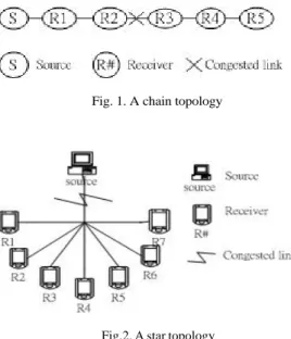
(4) where D 1 and D2 are predefined constants, as well as d(A , B) is the propagation delay between receiver A and B. SRM should use distinct constants of timer configuration in different topologies to avoid the NACK and repair implosion problems. Let us consider the chain topology in Fig. 1, sender S multicasts data packets to receiver R1 to R5, and the congested link is located between R2 and R3. Assume that delays of all links are all the same. In the case that a packet loss is occurred, receivers located at the downstream of R3 are all aware of the packet loss and will schedule request timers to send NACKs via multicast, while S, R1, and R2 will receive NACKs from downstream receivers and set their repair timers for issuing repair packets. To minimize number of NACKs and repair packets on the network, the sender and receivers can set these constants, C1 , C2 , D1 , and D2 , to 1, 0, 1, and 0, respectively. As the session sender and receivers use these constants for timer setting, there are at most one NACK and one repair packet on the network. Since these constants make timer setting become deterministic, this feature is so called deterministic suppression. Alternatively, let us consider the star topology as shown in Fig. 2. Assume a packet travels each link for one unit of time, and the packet is lost on the outgoing link of the source. In this scenario, all receivers will detect the loss of packet at the same time. Hence, a receiver can set C1 and D1 to 0, as well as C2 and D2 to 1, for keeping away from NACK and repair packets implosion problems. When the sender and receiver apply these constants, number of NACKs and repair packets on the network depends on the randomization of timer configuration. Because timers are set probabilistically, it is so called probabilistic suppression.. Fig. 1. A chain topology. Fig.2. A star topology. III. TIMER CONFIGURATION MECHANISM FOR SCALABLE RELIABLE MULTICAST (TSRM). The idea behind the TSRM is that a SRM receiver configures its request and repair timers based on the logical topology which is made by neighbors and itself. As mentioned before, different constants should be used in chain.
(5) and star topologies to minimize the number of NACKs and repair packets on the network. Hence, a receiver in TSRM exchanges information with other receivers to identify the logical topology and sets its request and repair timers accordingly. This section first describes the implementation of TSRM. Next, Parent Search Algorithm (PSA) and Timeout Decision Algorithm (TSA), which are used for topology detection and timer configuration in TSRM, are introduced. A. Implementation of TSRM Since deterministic suppression brings out the fewest NACKs and repair packets on the network, receivers had better form a chain topology. In other words, if a receiver can find out a “parent”, which refers to the nearest receiver on the path between the sender and itself, the NACK and repair implosion problems can be reduced. Because it can tune the request and repair timers such that its NACK and repair packet can be suppressed by those sent by the parent receiver. To find out a parent receiver, a receiver has to know relative positions of neighbors in a multicast routing tree by exchanging information with other receivers. In SRM, a “session message” is used for a receiver to estimate propagation delay between itself and other participant, either the session sender or other receiver. Hence, TSRM modifies the session message by adding a HC field in its header. The HC indicates the hop count between the sender and the generator of the session message. The usage of the HC field will be described later. For finding a parent and setting timers properly, TSRM defines following four new types of packets: routing information request (RIQ) packet, routing information reply (RIR) packet, timer setting (TS) packet, and parent-child (PC) packet. RIQ packets are used to request the routing path from the session sender and specific receiver and a RIR packet is for replying a RIQ. A RIQ packet comprises the identifier of a receiver and a RIR packet consists of a list of routers on the path between the session sender and itself. On the other hand, a TS packet, which contains two parameters, which will be described further in the following section, is used for a receiver to pass the information to configure timers. A PC packet is used for asking its parent to add the receiver into its child-list. Therefore, each receiver maintains a “child-list”, which includes IP addresses of receivers. A receiver only sends its timer setting to receivers that is recorded in its child-list. The detail of the TSRM works as follows. Assume that there is only one sender in a multicast session and routing paths between any two participants are roughly symmetric. A receiver first gathers the routing information, which consists of a list of routers between the receiver and the session sender, when it joins the group. The receiver then gathers the distance information based on HCs of received session messages. Specifically, HCs gathered during a session message exchanging interval will be used as input to the PSA to find out a parent receiver. A receiver may need to compare the routing path from the session sender to itself with that of to other receiver to clarify the relative position between them. Therefore, PSA may send a RIQ packet to a specific receiver and wait for a RIR packet to retrieve the routing path information from session sender to that receiver. After a parent is found, the receiver waits for a TS packet sent by its parent. Upon receiving the TS packet from its parent, the.
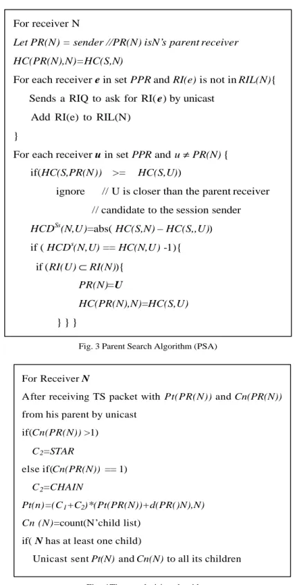
(6) receiver finally uses the TDA to configure its request and repair timers. B. Parent Search Algorithm (PSA) Before a receiver runs the PSA, it needs to perform some initial tasks. The first task is using “mtrace” tools to gather routing information when a receiver joins the group and knows who is the session sender. And the second task is to gather distance information from session messages. The distance information for a receiver, denoted by A, includes two parts. Receivers that have smaller hop count (shorter distance) to the sender than receiver A are put in a set called Potential Parent Receiver (PPR) set. The first part of the distance information is the hop counts from the session sender to receivers in PPR. The other part is the distances from receiver A to receivers in PPR. TSRM collects the distance information by “HC” field in the session message. After exchanging a few session messages, each receiver will have all the distance information it needs. The PSA is responsible for finding a parent receiver. Before describing the PSA, we first define some notations. Let HC(X,Y) be the hop count between two participants X and Y. X and Y can be either the sender or a receiver. Next, HCDS(X,Y) is defined as the absolute value of the difference between HC(S,X) and HC(S,Y), where S indicates the session sender. PPR(X) is viewed as a set of potential parents for a receiver X. Let PR(X) be the parent receiver of receiver X and RI(X) be the list of routers on the routing path from the sender to receiver X. Finally, let RIL(X) be a list of RI(Y), for all Y in PPR(X). In other words, RIL(X) is a routing information cache for receiver X. Fig. 3 shows the outline of the PSA. After receiving session messages from other receivers, the receiver N then chooses potential parent receivers. Receiver N first initiates its parent to be the session sender. Since the parent receiver always locates at the upstream side (toward the sender), receiver N selects each receiver M with HC (S, M) less than HC (S,N) as its potential parent receiver and puts it into the set of PPR . To clarify the relative position of potential parent receivers, it then sends RIQ packets to all the potential parent receivers. Upon receiving a RIR packet, it then caches the routing information into RIL(N). Now, receiver N has the ability to find out its parent receiver. It checks the HC(S,U) for every receiver U in PPR to see if it is less than the HC(S,PR(N)) (hop count of N’s potential parent receiver which is set in the last iteration). If yes, receive U may not be the parent receiver of receiver N, because it is not the closest ancestor of receiver N. Otherwise, receiver U may be the parent of receive N. To confirm this, receiver N checks if HCDS(N,U) equals to HC(N,U) minus one. If yes, it then checks the RI(N) and RI(U) to see if RI(U) is a proper subset of RI(N). If yes, it sets PR(N) to receiver U. Otherwise, receiver U is not the parent receiver of receiver N. The procedure is repeated until all receivers in PPR are checked. C. Timer configuration Based on the results of PSA, a receiver can now re-configure its request and repair timers. The request timer setup procedure uses a top-down approach which starts at the session sender. After a receiver finds its parent receiver, it sends a PC packet to its parent receiver to ask for adding it into the child list of its parent receiver. The receiver then waits for a TS packet sent by its parent receiver. A receiver needs to keep two kinds of information..
(7) First, a receiver needs to keep the type of topology information. A receiver is located at a star topology if he has siblings. Otherwise, it belongs to a chain topology. Second, a receiver needs to know the maximum delay for its parent receiver to send a NACK. The information is required to prevent a receiver setting a shorter delay than its parent receiver. The TSRM uses parameters Cn(X) and Pt(PR(X)) to keep these two kinds of information, where Cn(X) counts the number of receivers which choose receiver X as their parent receivers and Pt(PR(X)) is the maximum delay when the parent receiver of receiver X schedules a NACK. The timer configuration algorithm is shown in Fig. 4. When receiver N receives a TS packet, with Cn(PR(N)) and Pt(PR(N)) parameters, from its parent receiver, it first checks if Cn(PR(N)) is greater than 1. If yes, it sets the parameter C2 to the constant STAR since it has siblings. Otherwise, C2 is set to CHAIN. Since smaller C2 makes request timer setting more deterministic , CHAIN should be smaller than STAR for proper request timer setting in two kinds of topology. To prevent from sending a NACK earlier than the parent receiver, the lower bound of a request timer of a receiver should be larger than the upper bound of its parent receiver. Therefore, receiver N sets the lower bound of its request timer to C1 *(d(PR(N),N) +Pt(PR(N))), where Pt(PR(N)) is the upper bound of its parent receiver’s request timer. Specifically, receiver N sets its request timer from uniform distribution on. [C1 × ( Pt ( PR( N )) + d ( PR( N ), N )), (C1 + C2 ) × ( Pt( PR( N )) + d ( PR( N ), N ))] .. (3). After the setting of the request timer, receiver N will send a TS packet, with parameters Cn(N) and Pt(N)= (C1 +C2 )* (d(PR(N),N)+Pt(PR(N))), to receivers in its child-list if any receiver selects it as its parent receiver. 。.
(8) For receiver N Let PR(N) = sender //PR(N) isN’s parent receiver HC(PR(N),N)=HC(S,N) For each receiver e in set PPR and RI(e) is not in RIL(N){ Sends a RIQ to ask for RI( e) by unicast Add RI(e) to RIL(N) } For each receiver u in set PPR and u ≠ PR(N) { if(HC(S,PR(N)) ignore. >=. HC(S,U)). // U is closer than the parent receiver // candidate to the session sender. HCDSs(N,U)=abs( HC(S,N) – HC(S,,U)) if ( HCDs(N,U) == HC(N,U) -1){ if (RI(U) ⊂ RI(N)){ PR(N)=U HC(PR(N),N)=HC(S,U) }}} Fig. 3 Parent Search Algorithm (PSA). For Receiver N After receiving TS packet with Pt(PR(N)) and Cn(PR(N)) from his parent by unicast if(Cn(PR(N)) >1) C 2=STAR else if(Cn(PR(N)) == 1) C 2=CHAIN Pt(n)=(C 1+C2) *(Pt(PR(N))+d(PR()N),N) Cn (N)=count(N’child list) if( N has at least one child) Unicast sent Pt(N) and Cn(N) to all its children Fig. 4 Timeout decision algorithm. To minimize number of repair packets on the network, TSRM modifies the repair mechanism in SRM by changing retransmission candidates as well as the interval of repair timer. Instead of having arbitrary receivers to repair lost packets, only the parent receiver is responsible for repairing the lost packet of a receiver. According to.
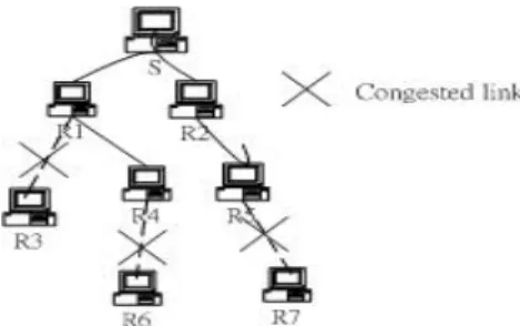
(9) the request timer setting in eq. 3, if a receiver N (or any downstream receiver of receiver N) and its parent receiver detect the same packet loss, a NACK sent by receiver N (or any downstream receiver of receiver N) will be suppressed by the one sent by its parent receiver or ancestor. In other words, there will be only one receiver sending the NACK on the same branch and it is the receiver closest to the sender which detected the packet loss. Therefore, when a receiver received a NACK, it will check its own child-list to see if the requestor is in its own child-list. If yes, then it will setup a timer for repairing the packet. Otherwise, it just ignores the request. Furthermore, to have an upstream node to effectively repair multiple losses at downstream, TSRM uses an improved version of the request timer configuration mechanism of SRM to configure the repair timer. Let us consider the case in Fig. 5, where S is the session sender and R1-R7 are receivers. Assume all links have the same link delay and receiver R3, R6 and R7 detect losses of a packet and then schedule their request timers to send NACKs. In this scenario, the parent receivers, which are R1, R4 and R5, will receive NACKs from their children receivers and send repair packets to repair the lost packet. If repair timer configuration method in SRM is used, the parent receivers will pick up their repair timers from the same interval, which increases the probability of having duplicate repair packets on the network. To solve this problem, TSRM further randomizes timer intervals of repair timers for different parent receivers. Specifically, a parent receiver A choose its repair timer from the uniform distribution on. [ D1 × d ( S , A), ( D1 + D2 ) × d ( S , A)] .. ( 4). In this case, a repair packet from the parent receiver that is closest to the session sender has higher probability to suppress retransmission from parent receivers that are farther away from the session sender.. Fig. 5 An example for time interval of repair timer. V. P ERFORMANCE EVALUATION. In this section, performance of TSRM is evaluated via simulations. Simulation of TSRM is implemented by modifying the SRM implementation in the network simulator (ns-2) [7]. We design three experiments to observe the performance of TSRM. The first experiment compares the scalability of TSRM with that of SRM. The second experiment examines the reliability of TSRM and SRM. In the final experiment, we compare the delay to receive a lost packet in TSRM and that in SRM. A. Simulation environment and parameters setting.
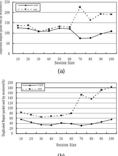
(10) Our simulation environment is shown in table 1. The simulation topology consists of 31 backbone nodes and 124 LAN nodes (each backbone has 4 LAN nodes). The bandwidth of a backbone link is 4.632Mbps, which equals to 3 T1 carriers, and that of a LAN link is 10 Mbps. The link propagation delay of backbone and LAN are 1ms and 0.1ms, respectively. Besides, both TSRM and SRM set the timer configuration parameters C1 , D1 , and C2 to 2, 2, and 1, respectively. And TSRM sets CHAIN and STAR to 1and 2, respectively; SRM sets C2 to 1. We assume packets will not lose due to link transmission error. A packet will be lost only when link buffer overflowed. Background traffic is introduced in our simulations to create the scenario of buffer overflow. Specifically, 20 TCP and 2 UDP sources are used to generate the background traffic. The multicast source sends packets at a constant bit rate (CBR) of 512Kbps. Furthermore, the multicast routing protocol is CBT. B. Scalability The fewer duplicated NACKs or repair packets sent, the better the scalability. Therefore, we evaluate the scalability of TSRM via two metrics: the ratio of average redundant NACKs to lost packets and the ratio of redundant repair packets to lost packets. Ideally, a lost packet only needs a NACK sent by the most upstream receiver which is closest to the link that drops the lost packet. TSRM is aimed to reduce the downstream receivers to send NACKs by proper timer configuration. Therefore, the first performance metric will evaluate whether NACKs have been reduced in TSRM as compare to SRM. Similarly, a lost packet also only requires one participant, either the session sender or a receiver, to retransmit the packet via multicast. Therefore, the second performance metric measures whether TSRM reduces redundant packets retransmitted. Fig. 6 shows the simulation results of these two metrics.. TABLE1. SIMULATION ENVIRONMENT SRM Topology. TSRM. 155 nodes (31 backbone node,124 LAN nodes) Backbone bandwidth is 4.632 Mbps Backbone propagation is 1 ms LAN bandwidth is 10Mbps LAN propagation is 0.1ms. Background traffic. 20 TCP sources 2 UDP sources (The packet sending rate is 25.6Kbps). Multicast traffic. 512Kbps Routing protocol :CBT. Timer parameters. C1=2, , C2=1,D1=2, D2=1. C1=2, D 1=2, D 2=1 STAR=2, CHAIN=1. Fig. 6(a) and (b) show the ratio of average redundant requests to lost packets and the ratio of repair packets to lost packets, respectively. Each simulation point plotted is the average of 10 simulation runs for the same session.
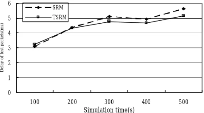
(11) size but different multicast members. From Fig. 6(a), we find that TSRM outperforms SRM, especially when session size is larger than 70. When session size is larger than 70, the network becomes very congested and, thus, more packet losses are expected. As we can see that TSRM greatly suppresses unnecessary NACKs. The reduction of the number of repair packets in TSRM is even more evident, as shown in Fig. 6(b). While the number of repair packets increases tremendously as the session size grows in SRM, the number is quite stable in TSRM. Therefore, TSRM is much more scalable than SRM. C. Reliability Since the number of NACKs and repair packets is greatly reduced in TSRM, it is necessary to make sure that TSRM has the same reliability as SRM. Since NACKs will be sent repeatedly until lost packets are recovered or the number of NACKs sent exceeds a pre-defined threshold in ns’s implementation of SRM, we observe only a few packets lost in our simulations. TSRM emulates SRM in sending NACKs repeatedly, so we also observe almost the same amount of packet losses in TSRM as in SRM. That is, SRM and TSRM have competitive performance in reliability. However, since TSRM yields less traffic as the number of NACKs and repair packets is reduced, TSRM is able to reduce packet transmission delay. Fig. 7 shows the percentage of packets loss rate, in average, by receivers at a certain point of (simulation) time. The percentage of packets received is defined as the number of loss packets which sequence numbers are less than the maximum one received by the same receiver over the maximum sequence number of the packet received by the receiver at that time. As we can see that less packet losses occurred in TSRM at a given instance of simulation time. D. The delay to receive a lost packet Another concern of TSRM is the delay to recover a lost packet since the timer configuration in TSRM yie lds slightly longer delay in sending NACKs and repair packets. Fig. 8 shows the average delay since a receiver observes a packet lost until the packet is successfully received. As we can observe that the delay in TSRM is competitive, or even shorter, than that in SRM. The rationale is that although the time to send NACKs and repair packets may be slightly longer in TSRM, the network traffic is also lighter and transmission delay is shorter as we observed in Fig. 7. Therefore, the overall delay to recover a lost packet in TSRM is competitive to that in SRM..
(12) Duplicated Request packet sent by receivers(%). 250 TSRM SRM. 200 150 100 50 0 10. 20. 30. 40. 50. 60. 70. 80. 90. 100. 90. 100. Session Size. Duplicated Repair packet sent by receivers(%). (a) 200. TSRM. 180 160 140. SRM. 120 100 80 60 40 20 0 10. 20. 30. 40. 50. 60. 70. 80. Session Size. (b) Figure 6: Comparing the scalability of TSRM and SRM. 10.4 10.2. SRM TSRM. Loss rate(%). 10 9.8 9.6 9.4 9.2 9 8.8 8.6 100. 200. 300. Simulaton time. 400. 500. Fig. 7. Comparison of the loss rate of TSRM and SRM: (Session size = 80).
(13) 6. SRM TSRM. Delay of lost packets(ms). 5 4 3 2 1 0 100. 200. 300. 400. 500. Simulation time(s) Fig. 8. Average delay for recovering a lost packet. (Session size = 80). VI. CONCLUSION AND FUTRUE WORK. In this paper, we have proposed a novel timer configuration mechanism, TSRM, to enhance the scalability of SRM. TSRM uses two efficient algorithms to decompose a multicast routing tree into chain and star topologies, re-configure request and repair timers, and change the retransmission mechanism in SRM based on the topology information. In our simulations, we have observed that TSRM yield good scalability, reliability, packet transmission delay, and delay for recovering a lost packet, as compared to SRM. For our future work, we plan to extend TSRM to support real time applications, such as voice and video streams. The timer configuration in TSRM is not suitable for real time applications as timing constraints are not considered. In particular, receivers near the bottom of the multicast tree may set its request timer to a very large value which may cause a long delay for receiving the retransmitted packet. For real time applications, delay constraints shall be considered in configuring request and repair timers. R EFERENCES. [1] M. Grossglauser. “Optimal Deterministic Timeouts for Reliable Scalable Multicast,” Proc. of the IEEE Infocomm’96, San Francisco, CA, Pages 1425-1432,March 1996. [2] S. Paul , K. K. Sabnani ., J.C.-H. Lin , S. Bhattacharyya , ”Reliable Multicast Transport Protocol(RMTP),” IEEE Journal on Selected Areas in Communications, Vol. 15, No.3, pp407-421,April 1997 [3] H. W. Holbrook, S. K. Singhal , and D. R. Cheriton, ”Log-based receiver reliable multicast for distributed interactive simulation,” Proc. of ACM SIGCOMM ’95, Oct. 1995, pp. 328-341 [4] B. Heinrichs , “AMTP : Towards a High Performance and configurable Multipeer Transfer Service,” in Architecture and Protocols for High-Speed Networks, Danthine Effelsberg, Spaniol (Eds.) , Kluwer Academic Publishers, 1994 [5] “XTP Protocol Definition”, Revision 3.6.Protocol Engine Incorporated, January 1992.
(14) [6] S. Floyd, V. Jacobson, C.-G. Liu, S. McCanne, and L. Zhang.,”A Reliable Multicast Framework for Light-Weight Sessions and Application Level Framing,” In ACM SIGCOMM Conference , Page 342-356,Aug 1995 [7] S. McCanne and S. Floyd, “LBNL Network Simulator, “http://www.isi.edu/nsnam/ns/”..
(15)
數據
+2
相關文件
In this paper, we propose a practical numerical method based on the LSM and the truncated SVD to reconstruct the support of the inhomogeneity in the acoustic equation with
Promote project learning, mathematical modeling, and problem-based learning to strengthen the ability to integrate and apply knowledge and skills, and make. calculated
Now, nearly all of the current flows through wire S since it has a much lower resistance than the light bulb. The light bulb does not glow because the current flowing through it
In summary, the main contribution of this paper is to propose a new family of smoothing functions and correct a flaw in an algorithm studied in [13], which is used to guarantee
Using this formalism we derive an exact differential equation for the partition function of two-dimensional gravity as a function of the string coupling constant that governs the
In addition, to incorporate the prior knowledge into design process, we generalise the Q(Γ (k) ) criterion and propose a new criterion exploiting prior information about
This kind of algorithm has also been a powerful tool for solving many other optimization problems, including symmetric cone complementarity problems [15, 16, 20–22], symmetric
In order to solve the problems mentioned above, the following chapters intend to make a study of the structure and system of The Significance of Kuangyin Sūtra, then to have
