國
立
交
通
大
學
資訊學院資訊科技(IT)產業研發碩士班
碩
士
論
文
點對點的多媒體近似直播串流儲存策略
P2P caching strategies for near live
media streaming
研 究 生:陳佩詩
指導教授:蔡文錦 教授
點對點的多媒體近似直播串流儲存策略
P2P caching strategies for near live media streaming
研 究 生:陳佩詩 Student:Pei-Shih Chen
指導教授:蔡文錦 Advisor:Wen-Jiin Tsai
國 立 交 通 大 學
資訊學院資訊科技(IT)產業研發碩士班
碩 士 論 文
A ThesisSubmitted to College of Computer Science National Chiao Tung University in partial Fulfillment of the Requirements
for the Degree of Master
in
Industrial Technology R & D Master Program on Computer Science and Engineering
September 2008
Hsinchu, Taiwan, Republic of China
i (
點 對 點 的 多 媒 體 近 似 直 播 串 流 儲 存 策 略
)學生:陳佩詩
指導教授:蔡文錦教授
國立交通大學
資訊學院產業研發碩士班
摘
要
點對點架構(peer to peer)是在 application 層建立協定,讓網路上的 peer 能 遵從一樣協定來進行溝通與傳輸資料。每個 peer 都可像主從式架構的客戶端去 尋找資源,也可像伺服器提供資料,回應他人需求。此篇論文模擬在網路的應 用層上,建立 p2p 的協定,利用像[3]的 mesh-pull 架構,做直播的多媒體串流 分享,並提出 peer 之間合作式的 cache 儲存協定,讓使用者可以選擇收過去播 過 的 多 媒 體 串 流 , 不 只 侷 限 在 直 播 的 串 流 。 我 們 稱 此 為 「 近 似 直 播 串 流 (Near-live streaming)」應用,其結合了直播(live streaming)與隨選播放(VoD) 功能於系統中。 一般直播多媒體系統多只儲存與直播節目最近期的資料,其 cache 資料更新採用 FIFO 的方法(或稱 continuous Overwriting),此種方法雖 然簡單卻在所提的近似直播的應用中,普遍有較差的效能。所以我們提出 No overwriting 的 caching , 與 前 述 方 法 做 互 補 。 為 了 適 合 更 多 數 的 video popularity 的情況,提出 Adaptive overwriting 的方法。實驗結果顯示所提的 caching 方法,特別是 Adaptive overwriting,在大多數的情況下昆能有較好 的效能。
ii
P2P caching strategies for media streaming
Student:
Pei-Shih ChenAdvisor:
Dr. Wen-Jiin TsaiI
ndustrial Technology R & D Master Program of
Computer Science College
National Chiao Tung University
ABSTRACT
The peer to peer communication is a protocol for user sharing computer resource and service over the application layer in the Internet. Every peer acts client and server, there is no central server. This paper extends the P2P protocol at live media streaming in [3] and proposes several cooperative caching strategies to provide “Near-live streaming service” which combines live streaming and VoD service in P2P systems. In these caching strategies, the simple and general method is continuous overwriting replacement, but it shows low hit rate in most of the cases for providing VoD services in the near-live streaming application. Therefore, we purpose a method called “No overwriting” caching, it mends drawbacks of the overwriting continuous method. But the “no overwriting” method still can’t satisfy the variable demand for users on large scale p2p system. Since this, we purpose an “adaptive overwriting” method that can suitable most of video popularity distribution. The simulation results demonstrate the superiority of the proposed methods.
iii
Table of Contents
ABSTRACT (Chinese)………..i
ABSTRACT ... ii
Table of Contents ... iii
List of Figures ... iv
List of Tables ... v
Chapter 1 Introduction ... 1
1.1. Live streaming ... 3
1.2. Video on Demand ... 4
1.3. Motivation ... 5
Chapter 2 Related Works ... 7
2.1. Proxy caching scheme ... 7
2.2. Replacement strategies ... 7
Chapter 3 Proposed near-live P2P streaming system ... 10
3.1. System architecture ... 10
3.2. Proposed protocol ... 13
3.2.1 Join phase ... 13
3.2.2 Work phase ... 14
3.2.3 Leave phase... 15
3.3. Proposed Cache Replacement strategies ... 16
3.3.1 Continuous Overwriting ... 16
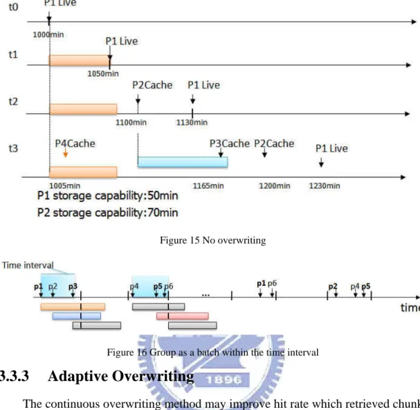
3.3.2 No overwriting ... 17
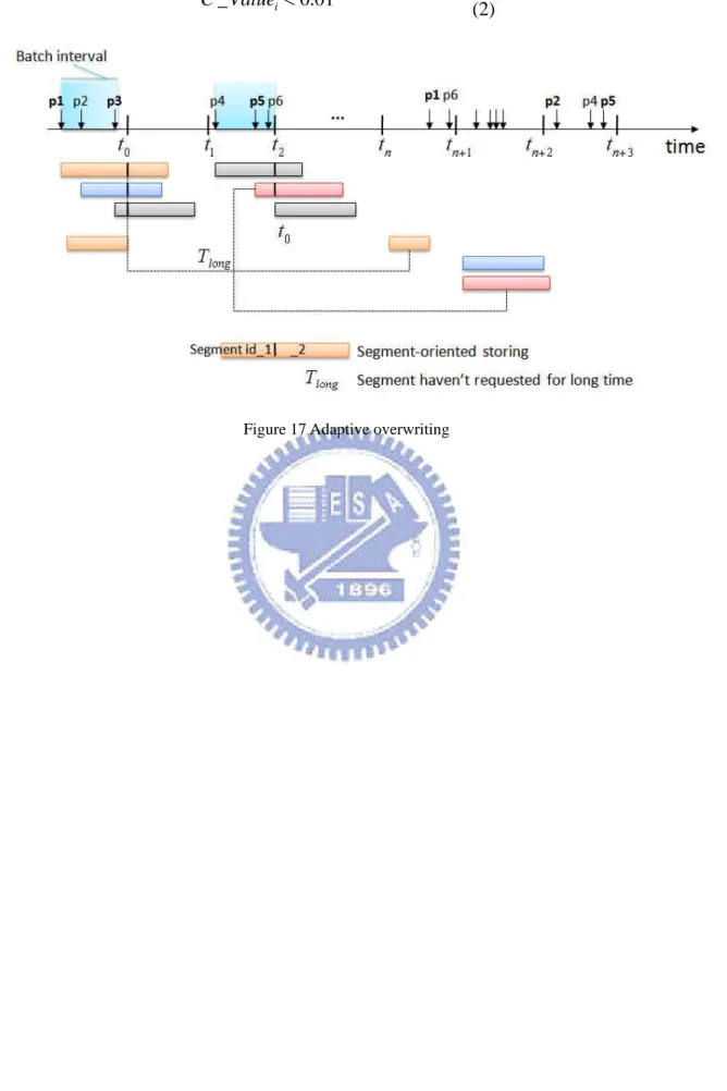
3.3.3 Adaptive Overwriting ... 18
Chapter 4 Experimental Results ... 21
4.1 Study of content popularity evolution ... 21
4.1.1 Zipf distribution ... 21
4.1.2 Video life cycle ... 22
4.2 Simulation setting ... 24
4.2.1 Topology ... 25
4.2.2 Parameters and complex popularity environment ... 25
4.2.3 User behavior ... 27
4.3 Analysis of result ... 28
4.3.1 Sliding window size ... 28
4.3.2 Experiment result ... 31
Chapter 5 Conclusion ... 37
iv
List of Figures
Figure 1 Centralized recovery, Flooded-request ... 2
Figure 2 Network application overlay for live streaming ... 3
Figure 3 Buffer map format ... 4
Figure 4 client in a session ... 5
Figure 5 proxy cache server ... 7
Figure 6 Playback data for each video in a time slot ... 9
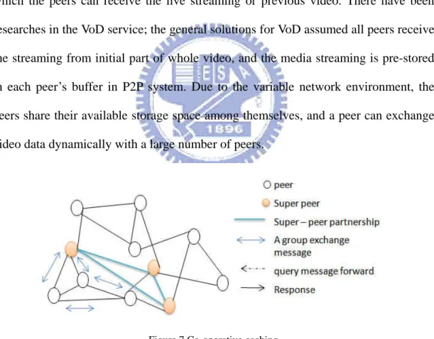
Figure 7 Co-operative caching ... 10
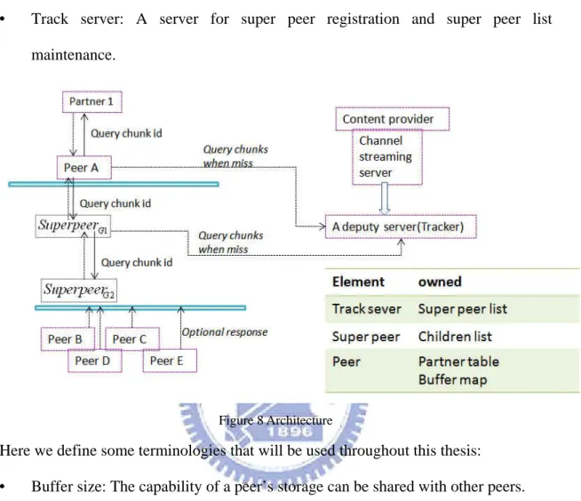
Figure 8 Architecture ... 11
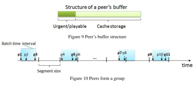
Figure 9 Peer’s buffer structure ... 12
Figure 10 Peers form a group... 12
Figure 11 Caching directory ... 13
Figure 12 New peer processes ... 14
Figure 13 Buffer map format of proposed protocol ... 15
Figure 14 Overwriting continuous ... 17
Figure 15 No overwriting... 18
Figure 16 Group as a batch within the time interval ... 18
Figure 17 Adaptive overwriting ... 20
Figure 18 (a, b) Comparison of different Zipf parameters ... 22
Figure 19 (a, b, c) Content life-cycles... 23
Figure 20 (a, b) Long-term life-cycles ... 24
Figure 21(a, b, c, d) Popularity ranked ... 31
Figure 22 (a, b) Instance for a serial requests ... 32
v
List of Tables
Table 1 Cache replacement strategies ... 8
Table 2 Relation between outgoing link and distance ... 25
Table 3 System parameters and default values ... 26
1
Chapter 1
Introduction
With the advances in high-performance network and digital video technology, the large-scale Video-on-demand (Vod) systems have come into practice in recent years. P2P technology is introduced for media streaming system for its scalability and low commercial cost. P2P is a distributed architecture consisting of a collection of resources (e.g. computing power, data, meta-data, network bandwidth) performing a distributed function. And every peer acted as either a client or a server. A general distinction of P2P architectures into three kinds is possible:
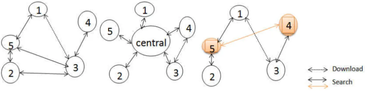
• Centralized:
There is a central directory. Each peer contributes its local “table of contents” to the central directory. Peer issues requests to the central directory to discover the most appropriate peer with the desired information. (E.g. Napster)
• Pure:
All peers perform equal functions. Requests of a peer are flooded from the original requestor to their neighbors and so on, recursively, for a number of steps or until the request is satisfied. The flooded-request is manipulated through network connectivity and the appropriate number of steps can result in good request coverage.
• Hybrid:
In pure P2P systems, it caused redundant messages for flooded-requests since the forwarding is performed recursively. Super peers are introduced for efficiency purposes in Kazaa P2P system.
2
Figure 1 Centralized recovery, Flooded-request and super peer model
P2P and multicast are two common transmission manipulations to provide scalable and cost efficient solution for either Video-on-Demand (VoD) or live streaming. P2P technology has been widely adopted in live streaming system. The overlay network is an application level construction that was separated from the physical network. By overlay construction method, they can be roughly classified into three main categories:
• Tree based overlay:
Peers are organized to form a tree-shape overlay network. By IP multicast support, data can transfer from a parent to multiple children as shown in figure 2 Enhance the efficiency of one-to-many and many to many communications over the internet. It concerns the way to build and maintain the tree. The parent peers in tree based overlay have a heavy burden in transferring data while leaf peers become isolation. On the other hand, the leave of parent peers caused tree adjustment which often affects the QoS (Quality of Service) of children peers. • Mesh-based overlay:
In mesh-based overlay, media data has been split into chunks and drive peers to get from multiple suppliers called partners. Meanwhile, each peer provides data to multiple “children”. The key issues in designing a mesh-based overlay include partnership management and data chunks scheduling algorithms. And a gossip based random algorithm is a solution to multicast message dissemination.
3
• Hybrid overlay:
It divides the transmission of control messages and media data into different overlays in [1]. The mechanisms of peer join, peer leave and peer selection can be optimized in control tree. Through the control tree, peers can easily find their neighbors to construct a transfer mesh.
Figure 2 Network application overlay for live streaming
1.1. Live streaming
There have been significant studies on live video streaming over Internet recently; see the surveys in [2], [3]. System with mesh-based overlay like CoolStreaming [2] is popular for its adaptability to dynamic networks. We now describe some important protocols in mesh-based P2P streaming system:
Gossip-based protocol:
It employs a gossiping protocol in data-driven overlay network (DONet) for partnership management. In a typical gossip algorithm, a node sends a newly generated message to a set of randomly selected nodes; those nodes do similarly in the next round, and so do other nodes until the message is spread to all.
Partner refinement
In mesh-based overlay, a peer can receive media data that has been split into chunks from multiple peers called “partner”, and each peer can provides available chunks for multiple “partner”. Since any node can depart accidentally in DONet, it’s necessary to
4
detect node failure for partnership refinement. It helps each node maintain a stable number of available partners by calculating a score for each partner. Let node j be the partner of node i. for node i, the score of partner node j is denoted byScorei,j.
j i Score, : Max{Si,j,Sj,i} − − WhereSi,j −
is the average number of segment that node i retrieved from node j. A partner that detects the failure will issue the departure message on behalf the failed node. And then the message is gossiped.
Chunk distribution protocol:
Every node periodically exchanges data availability information with a set of partners. The data availability information can be described as a buffer map.
Peer’s buffer map of video chunks:
As figure 3 shows the buffer map message includes the offset that the ID of the first chunk, the length of the buffer map, and a string of zeros and ones indicating which chunks are available. The BM playable video indicates the number of continuous chunks in the buffer map, beginning from the offset
Figure 3 buffer map format
1.2. Video on Demand
Several approaches have been explored in the past to tackle scalability issues faced by VoD service. IP multicast has been proposed to enhance the efficiency of
5
one-to-many and many-to-many communication over the Internet. A serial of IP multicast-based schemes, such as batching policy [4], has been developed that can drastically decrease the aggregate bandwidth requirement at the server. And both of [5] and [6] that based on P2P architecture proposed batching and patching scheme respectively. For instance, the P2P patching scheme in [6] can be partitioned into two functions for providing VoD service as following:
• Multicast for base stream forwarding:
As figure 4 illustrates, the clients that arrive within the threshold of time interval constitute a session. And the clients are able to forward the received base stream to other clients so that the server and clients can form an application-level multicast tree.
• Unicast for patching serving:
Every client need to have sufficient storage to cache the initial part of the video. So that the clients that earlier arrived can serve the patch to the later arriving clients.
Figure 4 Client in a session
1.3. Motivation
We have an idea to approach a live streaming coupled with VoD system. Instead of providing services from pre-stored videos on video servers as conditional VoD systems, we proposed a P2P system which services VoD from cached live streaming. Peers receiving live streaming will retain the segment consist of chunks that played until they leave. The later peers can choose either the live streaming or previous
6
programs (video). If the peers choose previous programs, they will retrieve data from other peers. We can exploit the data-driven overlay network to provide both of live streaming and VoD service without IP multicast support. Take the age of a segment retained in the storage into considerations; there are three proposed caching strategies. • Continuous Overwriting
• No Overwriting
7
Chapter 2
Related Works
Most previous studies of cache management have been focused on the cache replacement based on video caching proxies.
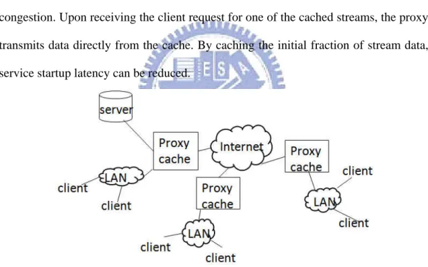
2.1. Proxy caching scheme
In general, proxy cache on the internet places nearby client along the path from the server to the client, as shown in figure 5 proxy stores a portion of a stream data or an entire stream in a cache. The content is pushed from the server to proxies or CDN servers close the clients. Client can choose the server that incurs the least amount of congestion. Upon receiving the client request for one of the cached streams, the proxy transmits data directly from the cache. By caching the initial fraction of stream data, service startup latency can be reduced.
Figure 5 Proxy cache server
2.2. Replacement strategies
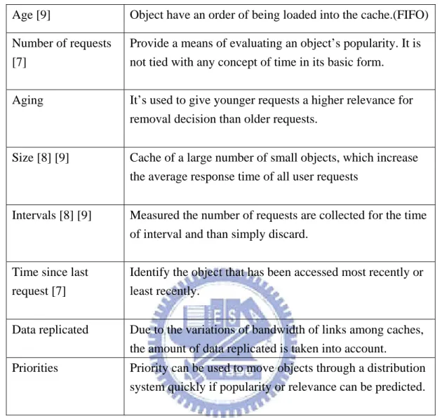
In table 1, we identify the elementary properties of cached objects that are taken into account in the removal decisions of caching algorithms. How the properties are used in replacement strategies are explained here in detail. Object will typically not fit into the allocated space completely, but only the initial of most recently used part is
8
store.
Age [9] Object have an order of being loaded into the cache.(FIFO)
Number of requests [7]
Provide a means of evaluating an object’s popularity. It is not tied with any concept of time in its basic form.
Aging It’s used to give younger requests a higher relevance for
removal decision than older requests.
Size [8] [9] Cache of a large number of small objects, which increase the average response time of all user requests
Intervals [8] [9] Measured the number of requests are collected for the time of interval and than simply discard.
Time since last request [7]
Identify the object that has been accessed most recently or least recently.
Data replicated Due to the variations of bandwidth of links among caches, the amount of data replicated is taken into account.
Priorities Priority can be used to move objects through a distribution system quickly if popularity or relevance can be predicted.
Table 1 Cache replacement strategies
The replacement policy of a proxy caching in [7] considered the number of requests and the last request time. A proxy has a caching value given by RF/ (T - T’), where T is the current time, T’ is the timestamp of the last request to this object, and the RF is the number of requests for this object since the time it enters the cache.
[8] has proposed the replacement policy which considered the size and interval. Each proxy server calculates caching utility value that represents the correlation between popularity of a stream and the size of cache space of a stream allocated. And then the victim stream which has minimum value is selected to be replaced. The caching utility in [8] is given by: