國 立 交 通 大 學
電信工程學系碩士班
碩 士 論 文
企業/家庭 無線區域網路閘道之乏晰允諾控制
Fuzzy CAC for WLAN Gateway in SOHO/Home
Networks
研 究 生︰吳俊憲
指導教授︰張仲儒 博士
企業/家庭 無線區域網路閘道之乏晰允諾控制
Fuzzy CAC for WLAN Gateway in SOHO/Home
Networks
研 究 生︰吳俊憲
Student:
Jiun-Shian
Wu
指導教授︰張仲儒 博士
Advisor:
Dr.
Chung-Ju
Chang
國立交通大學
電信工程學系碩士班
碩士論文
A Thesis
Submitted to Institute of Communication Engineering
College of Electrical Engineering and Computer Science
National Chiao Tung University
In Partial Fulfillment of the Requirements
For the Degree of Master of Science
In
Electrical Engineering
October 2004
Hsinchu, Taiwan, Republic of China
企業/家庭 無線區域網路閘道之乏晰允諾
控制
研究生︰吳俊憲
指導教授︰張仲儒 博士
國立交通大學電信工程學系碩士班
中文摘要
近年來企業/家庭無線區域網路的普及發展使得多種無線傳輸服務應用將成為主要 的趨勢,針對各種不同應用的服務品質,如何有效保證其服務品質並同時增進頻寬使用 效益將是系統設計的一大考驗。允諾控制為此提供了一個方法有效保證服務品質同時亦 能最大化頻寬使用效益。在此,允諾控制考慮新進服務的特性,要求的服務品質和系統 的剩餘資源以及系統量測品質做出決策。 針對各種不同問題,乏晰理論提供了一個有效簡單的邏輯設計。在本篇論文中我們 提出了一個乏晰允諾控制法則,針對企業/家庭 無線區域網路下的多種應用提供一個保 障服務品質的設計。並說明其設計的理念,確保此設計的正確性。我們提出一個比例性 的時間優先頻率排成提供不同服務品質之間的使用者有著比例分配的服務品質,並同時 藉由乏晰允諾控制提供不同使用者達到其要求服務品質。Fuzzy CAC for WLAN in SOHO/Home
Networks
Student: Jiun-Shien Wu
Advisor: Dr. Chung-Ju Chang
Institute of Communication Engineering
National Chiao Tung University
Abstract
In recent years, the popular development of SOHO/Home WLANs make the various service transmissions a major tendency in the future. For various quality of services (QoS), a real challenge of system design issues is how to guarantee these QoS and increase the utilization of system at the same time. Call admission control provides a effective method for QoS guarantee and also maximizing utilization. Here, call admission control consider the traffic characteristics and required QoS of a new call, the remaining resource of system and quality measured by system.
Fuzzy theorem provides a simple logic design for various problems. In this thesis, we provide fuzzy rules for call admission control in SOHO/Home networks, and the design could guarantee the various QoS in WLAN. We explain the reasons and principles for the design procedure. We also provide a weighted priority time period for the different services to make their quality as fair ratio relationship and we achieve the various QoS requirements through the fuzzy call admission control.
誌
謝
經過了許多波折,終於能趕在最後畢業,在此我要向所有關懷我的人表達我的感 謝之意。首先我要感謝指導教授張仲儒老師,老師的嚴謹處事態度以及關懷學生的出發 點讓我深深感動,一直以來老師都鼓勵我不要怠惰,從各種方法中讓我學習成長,在此 要向老師表達由衷的感謝之情。再來要感謝的是和老師一起共同指導我們的鄭瑞光學 長,犧牲假日,指導我們,並在人生的規劃、時間取捨上給了我很大心得,學長的樂觀 向上帶給我對事物的觀點更加寬廣。 此外還要感謝實驗室裡許多的夥伴在這段時間一起陪著我走過,首先要感謝立峰 學長,總是熱心的主動跟我一起討論分析我的問題,甚至在最後亦不厭其煩的教導我乏 晰理論,並且也常常在言談中分享生活的理念,告訴我一些助人為善的道理。再來要感 謝義昇學長在一開始給了我許多在研究上的觀念和想法,以及詠瀚學長幫我釐清 spec 的相關設定。另外還有家慶學長大力幫忙我釐清系統的架構設定。最後要感謝這兩年來 一起陪伴的同窗同學,崇禎和皓棠,一路走來這條路真的不孤單,更要謝謝你們最後關 頭,遠道而來的全力幫忙,沒有你們這些好兄弟,今天就沒有機會寫誌謝了! 另外還要感謝常常幫我買便當的學弟,因為你們,我才有力氣繼續做論文。也要 感謝凱盟學長在我低潮時的問候與青毓學姐的鼓勵。在這兒要向遠在加拿大的青毓學姐 加油打氣,更期待妳和立峰學長的誌謝。 最後要給學弟一些勉勵的話,老師常說:鑑古知今,千萬要記住我的心得教訓。 僅將這篇論文獻給老師和 701 的伙伴 吳俊憲 謹誌 民國九十三年Contents
中文摘要... i
Abstract... ii
Acknowledgement ... iii
Contents ... iv
List of Figures...v
List of Tables... vi
Chapter 1 Introduction...1
Chapter 2 Simulation Study of IEEE 802.11e HCF on Hybrid services...4
2.1. System Model... 4
2.1.1. System Architecture ... 4
2.1.2. System Operation... 5
2.2. Traffic Source Models ... 8
2.3. Simulation Results ... 11
2.4. Concluding Remarks... 15
Chapter 3 Fuzzy Call Admission Control (CAC) for WLAN Gateway in
SOHO/Home Networks ...22
3.1. Introduction... 22
3.2. System Model ... 22
3.2.1. System Architecture…...………..22
3.2.2. Related Work on WLAN Operations..………...………..23
3.2.3. Scheduling for Weighted QoS in Video Services..………..29
3.2.4. Traffic Source………..…………...………..30
3.3. Fuzzy Call Admission Control... 35
3.3.1. The Goal... 35
3.3.2. Fuzzy Call Admission controller ... 35
3.4. A Gaussian Approximation for Equivalent CAP Estimator ... 41
3.5. Concluding Remarks... 42
Chapter 4 Conclusion ...43
Bibliography ...44
List of Figures
Figure 2.1: Indoor SOHO WLAN Infrastructure Environment... 4
Figure 2.2: An example of a superframe timing ... 5
Figure 2.3: The four-state Markov model of a conversation pair ... 9
Figure 2.4(a): State transition diagram for interframe coding ... 10
Figure 2.4(b): State transition diagram for difference coding... 11
Figure 2.4(c): Interframe and intraframe alternate model for a video source... 11
Figure 2.5: Average CAP period versus number of voice pairs... 16
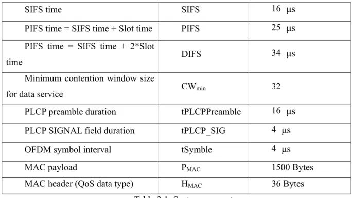
Figure 2.6: Average voice CAP period versus number of voice pairs ... 17
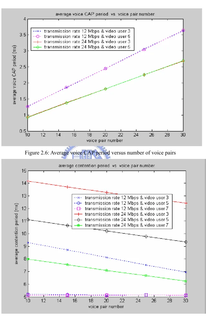
Figure 2.7: Average CP versus number of voice pairs ... 17
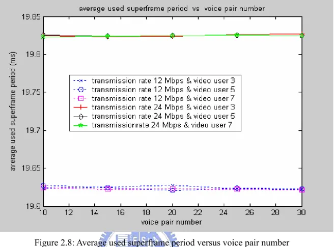
Figure 2.8: Average used superframe period versus voice pair number ... 18
Figure 2.9: Average real-time service period versus voice pair number... 18
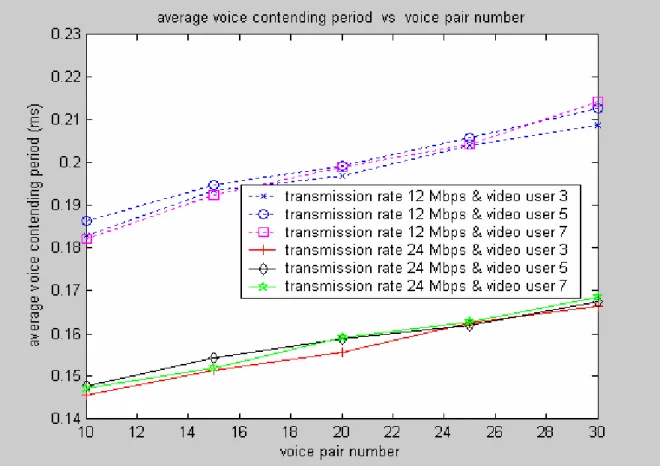
Figure 2.10: Average voice contending period versus number of voice pairs ... 19
Figure 2.11: Average frame drop rate versus number of video users... 19
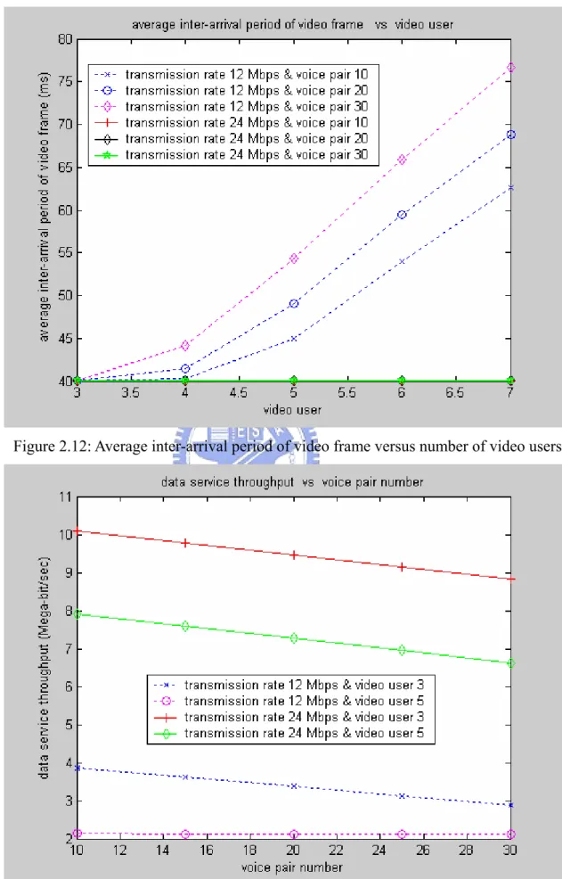
Figure 2.12: Average inter-arrival period of video frame versus number of video users ... 20
Figure 2.13: Average data service throughput versus number of voice pairs ... 20
Figure 2.14: Video service throughput versus number of voice pairs ... 21
Figure 3.1: An infrastructure of SOHO/Home networks ... 23
Figure 3.2: An example of a timing arrangement during a superframe. ... 24
Figure 3.3: The four-state Markov model of a conversation pair ... 31
Figure 3.4(a): State transition diagram for interframe coding ... 32
Figure 3.4(b): State transition diagram for difference coding... 32
Figure 3.4(c): Interframe and intraframe alternate model for a video source... 33
Figure 3.5: Synthetic self-similar traffic generator... 34
Figure 3.6: ON/OFF Parato-distributed source... 34
Figure 3.7: Block diagram of the fuzzy call admission control... 38
Figure 3.8: The membership function of the term set for Data loss index ... 39
Figure 3.9: The membership function of the term set for CAP index... 39
Figure 3.10: The membership function of the term set for Real-time drop index ... 39
List of Tables
Table 2.1. System Parameters ... 12 Table 3.1. The rule structure for the fuzzy admission controller ... 41
Chapter 1
Introduction
Wireless local area networks (WLAN) are being developed to provide high bandwidth to users in a limited geographical area, and WLAN will then be attached to backbone networks like the Internet, or interface to wireless wide area networks (WAN) for range extension. In recent years, the IEEE 802.11 WLAN has become a prevailing broadband wireless technology [1], and the IEEE 802.11 WLAN can be considered as a wireless version of Ethernet, which supports best-effort service. However, not only data transmissions are concerned but also multimedia traffic requiring constant, variable, and available bit rate services will be employed on WLAN in this future.
At present, the IEEE 802.11 standard MAC protocol supports two kinds of access methods: DCF (Distributed Coordination Function) and PCF (Point Coordination Function). The performance of the DCF has already been studied in many literature researchers [2-5]. Regarding the PCF, we can find performance evaluation taking into account voice or video transmission with the PCF [6-9]. In [6], the combined performance of data transmission with the DCF and voice transmission with PCF is evaluated. The authors studied the combined performance of data transmission with DCF and video transmission with the PCF in [7]. Performance evaluation considering video transmission with the PCF could also be found in [8]. In [9], the performance of priority-based multimedia transmission with PCF was evaluated.
Also, for quality of service (QoS) in application services, IEEE 802.11 Task Group E currently defines enhancements to 802.11 MAC, called 802.11e [10], which introduces a hybrid coordination function (HCF). The HCF consists of a contention-based channel access called enhanced distributed channel access (EDCA) mechanism for contention-based transfer and a controlled channel access, referred to as HCF Controlled Channel Access (HCCA) mechanism, for contention free transfer.
This new standard provides the means of prioritizing the radio channel access by different stations and media access control (MAC) data streams. Stations, which operate under the 802.11e and provide the QoS facility, are called QoS stations (QSTAs), and a QoS
station, which works as the centralized controller for all other QSTAs within the same basic service set, is called Hybrid Coordinator (HC). The HC will typically reside within an 802.11e QoS access point (QAP) connecting its QSTAs with infrastructure.
A basic unit of allocation the right to transmit onto the wireless medium (WM) is the transmission opportunity (TXOP). A TXOP is defined as an interval of time when a particular QSTA has the right to initiate transmissions, and defined by a starting time and a maximum duration. The TXOP may be obtained by QSTA winning an instance of EDCF during the contention period (CP) called EDCA TXOP , or by QSTA receiving a QoS(+) CF-Poll during the CP or contention free period (CFP) called HCCA TXOP or polled TXOP. The duration of an EDCA TXOP is limited by TXOP Limit distributed by the HC in beacon frames and includes the time required to transmit frames sent as an immediate response to TXOP holder. An essential characteristic of 802.11e is that HC operates during both the CP and CFP which gives a HC the highest priority in medium access. And a controlled access phase (CAP) is a time period when the HC maintains control of the medium, after sensing the channel to be idle for a PCF Interframe Space (PIFS) duration and gaining access to the medium. A CAP may span multiple consecutive transmission opportunities (TXOPs) and may contain several polled TXOPs.
The EDCA is based on Carrier Sense Multiple Access/Collision Avoidance (CSMA/CA), and supports four access categories (ACs). The four ACs are best effort, background, video, and voice, and each AC is a common set of EDCA parameters that are information of AIFS, CWmin, CWmax, and TXOP Limit used by a QSTA for contention of the channel for the transmission of MAC service data units (MSDUs) with certain priorities, where AIFS is the arbitration interframe space (AIFS), and CWmin/CWmax is the minimum/maximum of the contention window (CW) of the AC. Different EDCA parameters of the four ACs are broadcasted in the beacon by the HC, and the minimum AIFS for a QAP is PCF interframe space (PIFS) smaller than the DCF interfrane space (DIFS), the minimum AIFS for a
non-QAP QSTA. The CWmin/CWmax has the range of 0 to 32767 from 2 1i− where i is the
integer from 0 to 15. There are four CWs of associated AC, as referred to CW[AC], which shall be initialized to the value of the parameter CWmin[AC]. And for each AC, the corresponding backoff timer is set to an integer value chosen randomly with a uniform distribution in the range [0, CW[AC]]. The CW[AC] may be updated to the value (CW[AC]+1)*2-1 if CW[AC] is less than CWmax[AC], or remain unchanged for the remainder of retries if the CW[AC] is equal to the CWmax[AC].
In this thesis, we adopt the HCF which a CAP is generated periodically in the beginning of a superframe after sensing the channel to be idle for PIFS duration, and our system is based on 802.11e draft 6.0 with 802.11a for physical layer transmission.
In chapter 2, we proposed a modified method with inter frame space (IFS) for data transmission avoiding much idle time for data contending access. The system we consider is with full queue traffic model, voice service access would be transmitted in the CAP and CP and video service is transmitted in the CAP. In section 2.1, system model is described including system architecture and system operation on 802.11. In the section 2.2, we describe traffic sources which are voice, video and data traffics in the system. In section 2.3, we discuss the simulation results under the figures about throughput, drop rate, inter-arrival delay of the related service. Finally, we have concluding remarks in section 2.4.
The chapter 3 is outlined as follows. In section 3.1 some respects of call admission control are introduced under various traffics in the wireless system. In section 3.2, the system model is described including the system architecture, the related call request operation, system operation in 802.11 and traffic sources are described including video, voice, and data traffic. In section 3.3, the fuzzy call admission control is described including the goal, the fuzzy call admission controller and fuzzy rules. In the section 3.4, we describe the Gaussian approximation used for the equivalent CAP estimator. Finally, concluding remarks are given in section 3.5.
Chapter 2
Simulation Study of IEEE 802.11e HCF on
Hybrid Services
2.1 System
Model
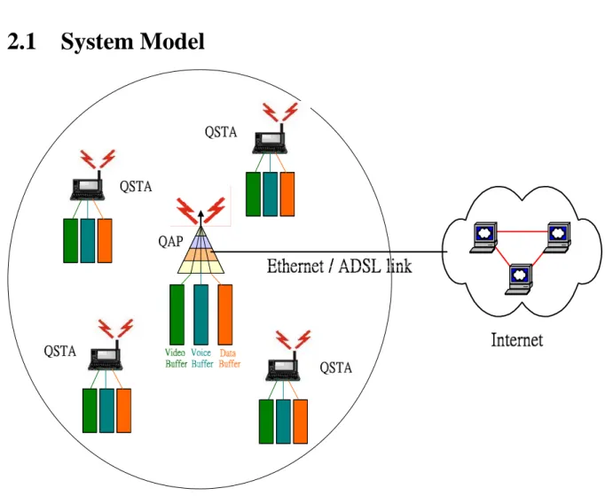
Figure 2.1: Indoor SOHO WLAN Infrastructure Environment
2.1.1 System Architecture
For an indoor SOHO WLAN environment shown in figure 2.1, there is a QoS access point (QAP) having only two interfaces, an Ethernet interface and an 802.11e interface. The Ethernet/ADSL link supports the data traffic and the real time service traffic sent from or to
the Internet, and the 802.11e interface is used to transmission of the packets in the wireless environment. In this thesis, the end host is called the quality of service station (QSTA) for which we intend to provide the quality of service (QoS) facility. In the infrastructure environment of Small Office, Home Office (SOHO), we assume that all video, voice, and data packets are sent through the QAP even though in some cases, when both QSTAs are within in the coverage area of an QAP, voice and data packets could not be sent directly between the QSTAs.
data
AIFS AIFSvo
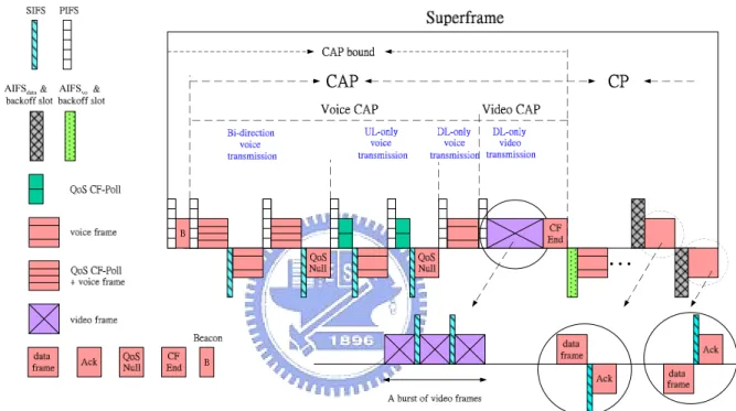
Figure 2.2: An example of a superframe timing
2.1.2 System Operation
In a superframe, it can be divided into two periods: controlled access phase (CAP) and contention period (CP) as shown in Fig. 2.2. In the CAP, the QAP polls the QSTAs to get the uplink voice frames or transmits the downlink voice frames and the downlink video packets directly without acknowledge based on HCF controlled channel access. In the CP, the non-real time data frames and intended contending voice frames of QSTAs would use different priorities to contend the channel based on EDCF.
The CAP within a superframe can be divided into two transmission phase: Voice CAP, and Video CAP. In addition, the voice service within a Voice CAP also can be sequentially served into three transmission period: bi-direction voice transmission, uplink-only (UL-only)
voice transmission, and downlink-only (DL-only) voice transmission. In a superframe, there is at most one voice frame for uplink transmission of a QSTA, and also the QAP has at most one downlink voice frame for each QSTA with the conversation. At the beginning of the Voice CAP, the QAP decides the polling sequence based on the polling list. The first voice service of polling sequence is bi-direction voice transmission. If the QAP has a downlink voice frame queued for transmission to the QSTA in the polling list at the QAP, the downlink voice frame and QoS(+)CF-Poll can be combined and transmitted as a single frame by the QAP after the channel is sensed to be idle for a PIFS interval. After receiving the frame, the destination of the QSTA can transmit an uplink voice frame to the QAP after a SIFS interval. This frame exchange procedure is called bi-direction voice transmission. After bi-direction voice transmission, for the QSTA in polling list but the QAP does not have a voice frame queued for it, the QAP sends a sole QoS(+)CF-Poll frame to the QSTA after the channel is sensed to be idle for a PIFS interval, and waits to receive an uplink voice frame from the QSTA after a SIFS interval. This frame exchange procedure is called uplink-only (UL-only) voice transmission. If the QAP receives a QoS Null frame from the QSTA during bi-direction voice transmission or UL-only voice transmission, the QAP regards the QSTA entering into silence period and removes the QSTA from the polling list in the QAP. After UL-only voice transmission, the QAP consecutively sends the remaining downlink voice frames with no acknowledge after waiting a PIFS channel idle interval during downlink-only (DL-only) voice transmission.
In the Video CAP, the QAP sends the multiple video packets belong to the QSTA in a burst and Round Robin manner after the channel is sensed to be idle for a PIFS interval. During the frame interval, the QAP receives several video packets of the frame interval belong to the QSTA from Ethernet/ADSL link and the QAP may transmit these video packets during the following three CAPs in a burst without acknowledge which are separated by SIFS interval in the video CAP. These video packets in the QAP are lasting availably for the following three CAPs or until they are transmitted completely. While these video packets are not completely transmitted by QAP during the following three CAPs, the QAP would not transmit these packets which are dropped by the QAP, and the QAP will transmit the at most packets of next frame interval. During the following two CAPs, if there are enough residual time in the CAP bound for a video packet transmission, the QAP sends the packet belong to the QSTA which is at service turn and also sends the remaining packets at next video CAP in first after the channel is sensed to be idle for a PIFS interval. The video packets belong to a
QSTA may be transmitted in two consecutive video CAPs. Each video burst transmission on the wireless medium is corresponding to several video packets arriving at the QAP during a frame interval intended to a QSTA. After the QAP transmits a burst of video packets to a QSTA, the QAP continues to transmit another video burst of the next QSTA in a cyclic manner (that is so called Round Robin) after a PIFS channel idle interval. In addition, after all bursts of the frame interval are transmitted, the QAP consecutively transmits the bursts of the next frame interval if they are all arrived at QAP. In addition, until all bursts of video packets arriving at QAP before the superframe are transmitted completely by the QAP, and QAP sends a CF-end frame as termination of the video CAP. Fig. 2.2 shows an example of a superframe timing.
In the CP, the voice frames for uplink but not polled during the voice CAP in the same superframe will contend with data frames. The data frames including QAP downlink data
frames and QSTA uplink data frames. The QAP should assign different AIFS, CW , and min
max
CW for the contending uplink voice service and data service. After the QAP receives an
uplink contending successful voice frame from the QSTA, the QAP re-adds the QSTA in the polling list. When the counter of a data frame contending for transmission counts down to zero and there is enough time for a complete data frame exchange in CP, the QSTA would transmit the data frame. Also, it happens to a data frame having zero-counter in the beginning of the CP because there is not enough access time for the frame exchange in the last CP. In the beginning of the CP, if a data frame is first transmitted, the voice service would delay for at least a data frame transmission period in spite of the collision happened or not. In order to guarantee the voice delay as small as possible, the AIFS for voice service is set to equal to PIFS, denote as AIFSvo =PIFS. And the CW of a voice frame, denote as min CWmin_vo, and
max
CW of a voice packet, as CWmax_vo are given by
{
}
min_vo max_vo [ ] if 1 CW CW max 2, [ ] if 2 C NP C NP E N N E N N ⎧ ⎡ ⎤ ≤ ⎪ ⎢ ⎥ = = ⎨ ≥ ⎡ ⎤ ⎢ ⎥ ⎪⎩ (2.1)where NC is the number of voice packets contending in a superframe, NNP is the
number of QSTA with voice conversation not in the polling list, and [E NC] is the average
contending voice packet number of the superframe which may be zero if NNP is equal to
zero. Also the CWmin_vo and CWmax_vo is the smallest integer greater or equal to the mean value of NC. Here, we guarantee that the contending uplink voice service has a higher priority
than non-real-time data service. That is the contending voice frames are always served before the data frames. In a CP, when a data frame of a QSTA is served in the CP, it stands for contending voice frames has been completely served and hereafter only the data frames contend with each other in the CP. In order to avoid the uplink contending voice frame to be terminated by non-real-time data frames, the AIFS of non-real-time data service, denote as AIFSdata is given by
max_vo data
for the first frame transmitted of a QSTA in a CP others PIFS SlotTime (CW 1) AIFS DIFS + ∗ + ⎧ = ⎨ ⎩ (2.2)
where the “+1” is for contending uplink voice frames avoiding collision with a data frame having zero-counter. The minimum and maximum contention window of a data frame,CWmin_data and CWmax_data, could be variable set by the retransmit times of the data frame. And CWmin_data and CWmax_data of the first frame of a QSTA in a superframe are the same and not changed even during the retransmissions. If a data frame is retransmitted five times and it is still not successful, the data frame is dropped by the QSTA.
2.2 Traffic
Source
Models
Now we describe our traffic source models. The services we want to support are voice, video and data traffic.
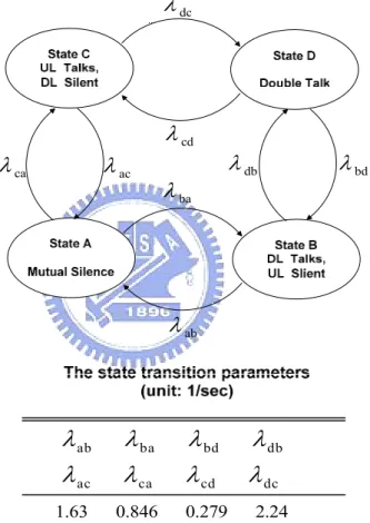
Voice traffic: As shown in Fig. 2.3, the conversational dynamics of a communication pair is modeled as a four-state model, and the random process of conversational pairs in the coverage of a QAP is assumed to be independent and identically distributed. The four-state is described as follows that uplink and downlink are both talking, called Double Talk; Uplink and downlink are both silent, called Mutual Silence; Uplink is talking and downlink is silent, defined as Talkspurt; Uplink is silent and downlink is talking, defined as Pause. In the model, the sojourn time of each state in which a conversation pair state is assumed to be exponentially distributed. The state transition rates,
λ
ij , can be obtained by fitting the mean duration of talkspurt, pause, double talk, and mutual silence, given in [11]. Within eachtalking spurt interval for each member of a conversational pair, 8 kb/s pulse code modulated (PCM) digital voice is assumed and the mean rate of a communication pair given parameters in Fig. 2.3 is 6.8 kb/s. During a talking spurt interval, a voice frame is coded every superframe interval and the coder generates some voice frames which are all the same size depending on the coding rate and superframe interval. We consider the superframe interval as the maximum acceptable value for one-way voice transfer delay over the WLAN delay. When a voice frame is not transmitted successfully in this superframe, it is dropped by the QAP or QSTA dc
λ
acλ
caλ
cdλ
bdλ
baλ
λ
db ab ba bd db ac ca cd dcλ
λ
λ
λ
λ
λ
λ
λ
1.63 0.846 0.279 2.24 abλ
Figure 2.3: The four-state Markov model of a conversation pair
Video traffic: In the article, the frame generation process for a video coder was assumed to have two motion states: the low motion state for the rate of interframe coding, and the high motion state for rate of intraframe coding. The rate of intraframe coding was further divided into two parts: the first part had the same rate as the interframe coding and the second part, called difference coding, was the difference rate between intraframe coding and interframe coding [12]. The interframe coding and the difference coding were both modeled as discrete-state Markov-modulated poisson process (MMPP) with basic rates A r and A a
[13]. The state-transition diagram is shown in Fig. 2.3(a) and 2.3(b). The video source will alternate between interframe and intraframe, depending on the video source activity factor. As shown in Fig. 2.4(c), there is a transition rate c in the interframe state and a transition rate d in the intraframe state. Let
λ
a( )t ,λr( )t ,λ
'a( )t denote the frame generation ratesfor intraframe coding, interframe coding, and difference coding at the time t, respectively,
from the video coder. Clearly, ( ) ( ) ' ( )
a t r t a t
λ
=λ
+λ
The process of λr( )t is an(Mr +1)-state MMPP process. The state-transition diagram for λr( )t uses the label m Ar r
to indicate the frame generation rate of interframe coding of a state and use the labels
(Mr −mr)γ and mrω to denote the transition rate from state m Ar r to state (mr +1)Ar,
and from state m Ar r to state (mr −1)Ar, respectively. Similarly, the process for
λ
'a( )t isan (Ma +1)-state birth-death Markov process. The state-transition diagram for
' ( )
a t
λ
usesthe label m Aa a to indicate the additional frame generation rate of a state due to intraframe
coding and uses the labels (Ma −ma)φ and maϕ to denote the transition rate from state
a a
m A to state (ma+1)Aa and from state m Aa a to state (ma −1)Aa, respectively. One
should be note that the long-term correlation behavior of a video source results from the process
λ
a( )t.
The values ofγ ω
, , , , , ,Mr Arφ ϕ
Ma, , Aa c and dcan be obtainedfrom the traffic variables of Rp ,
m
R and
p
T [13,14]. It was assumed
that Rp = 4.95 Mbps, Rm =1.65 Mbps, 0.5Tp = second, which
give Mr =Ma =20 , 5 2.01 10 r A = × bit/sec, Aa =4.71 10× 4 bit/sec, γ =1.33 , ω =2 , 1 φ ϕ= = , c=2, and d =18.01 (1/ sec).
γ
r M (Mr −2)γ
(Mr −mr+1)γ
(Mr−mr)γ
γ
ω
r M (mr+1)ω
2ω
ω
3ω
r A 2 r A m Ar r M Ar r 1)γ
− r (Mω
r mφ
a M (Ma−1)φ
(Ma −2)φ
(Ma −ma+1)φ
(Ma−ma)φ
φ
(ma+1)ψ
Maψ
ψ
a m 3ψ
2ψ
ψ
aA
2
A
am A
a aM A
a aFigure 2.4(b): State transition diagram for difference coding ' ( )
a t
λ
c
d
Figure 2.4(c): Interframe and intraframe alternate model for a video source
Data traffic: We have an assumption for data traffic that there is always a data frame of a QSTA ready to be sent. When a data frame is transmitted or dropped by a QSTA/QAP, there is always another data frame in QSTA/QAP intended for contenting the wireless medium at instant.
2.3 Simulation
Results
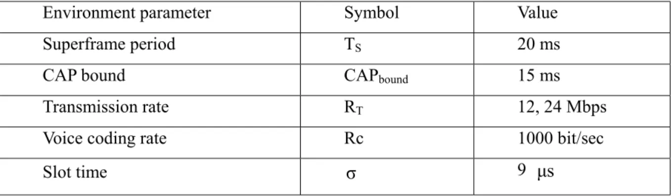
Parameters of the simulation environment are set in the Table 1.1, and the values of PHY-related parameters were referred to IEEE 802.11a [16].
Environment parameter Symbol Value
Superframe period TS 20 ms
CAP bound CAPbound 15 ms
Transmission rate RT 12, 24 Mbps
Voice coding rate Rc 1000 bit/sec
SIFS time SIFS 16 µs
PIFS time = SIFS time + Slot time PIFS 25 µs
PIFS time = SIFS time + 2*Slot
time DIFS 34 µs
Minimum contention window size
for data service CWmin 32
PLCP preamble duration tPLCPPreamble 16 µs
PLCP SIGNAL field duration tPLCP_SIG 4 µs
OFDM symbol interval tSymble 4 µs
MAC payload PMAC 1500 Bytes
MAC header (QoS data type) HMAC 36 Bytes
Table 2.1: System parameters
Figure 2.5 shows the average CAP period versus the voice pair number with six scenarios, and figure 2.6 shows the average voice CAP period versus the voice pair number with four scenarios. In figure 2.5, for the two scenarios of transmission rate 12 Mbps & video user 5 and 7, the average CAP period is saturated and almost the same whether the voice pair increases or not. The saturation phenomenon under the two scenarios results in that transmission rate 12 Mbps & CAPbound (15 ms) could not support more than five video users with a low drop rate. At the scenario of transmission rate 12 Mbps & video user 5, when the voice pair number is 10, the average CAP period is lightly smaller than the saturation parallel line, and video frames have been already dropped in some degree. The gap between the average maximum CAP period and CAPbound is about half of a video packet transmission interval with payload is 1500 bytes. The factor of this gap is resulted from the 802.11e transmission rule, and the value of this gap is about 0.5 ms for the transmission rate 12 Mbps and the payload of a video packet size, 1500 bytes. For the other four scenarios, the increasing amount of the average CAP period for transmission rate 12/24 Mbps with voice pair number increasing is equal to the increasing of average voice CAP period for transmission rate 12/24 Mbps with voice pair number increasing in Figure 2.6. The increasing amount of average CAP period while increasing voice pair number could be approximated as follows:
4 =1 s voice voice-payload R p 1
( ) ( )
T
ip i
⋅
t i
∆
=
∑
(2.3)where Pvoice-payload is the payload of the voice packet (20 byte),Rvoice is the mean rate of a voice pair (6.8 kbps) in figure 2.3,
p i
( )
is corresponding probability at the state in figure 2.3 andt i
( )
is the time interval for a voice pair transmission at the state. The∆
=0.12 and 0.9 (ms per pair) for transmission rate 12 and 24 Mbps are the same as figure 2.6. In figure 2.6, the average voice CAP period is independent of the video users because the transmission priority of voice transmission is higher than the video packet transmission.Figure 2.7 shows the average contention period (CP) versus the voice pair number, and
the sum of figure 2.6 and figure 2.7 is the superframe period (
T
s= 20 ms). For the twoscenarios of transmission rate 12 Mbps & video user 5 and 7, the average contention period achieves the minimum when the average CAP period achieves the maximum value and video packets has been dropped obviously. For the other four scenarios, while the voice pair number increases, the average contention period reduces because the voice transmission is prior to data transmission, and the reducing amount of average contention period for transmission rate 12/24 Mbps with voice pair number increasing is equal to the increasing amount of average voice CAP period for transmission rate 12/24 Mbps with voice pair number increasing in Figure 2.6.
Figure 2.8 shows the average used superframe period versus the voice pair number. The average used superframe period is all the same just depending on the transmission rate. While the gap interval between the average used superframe period and superframe period (
T
s) is about the half of a data frame transmission interval depending on the transmission rate.Figure 2.9 shows the average real time service period versus the voice pair number. The period includes the CAP period and voice contending period. Figure 2.10 shows the average voice contending period versus the voice pair number. The average voice contending period increase with the voice pair number increasing. The figure 2.9 can be added form the figure 2.1 and figure 2.10, and because the average voice contending period is much smaller than the average CAP period, the figure 2.1 and figure 2.9 are similar.
Figure 2.11 shows the average video frame drop rate versus the video users. For the transmission rate 12 Mbps, video frames begin to be dropped when there are four video users,
and dramatically increases with video user increasing. While the voice pair number increases, the average video frame drop rate also increases because the video CAP period is reducing. When the video user is five, the average CAP period reaches the maximum and hereafter the increasing of voice pair number would make the average video drop rate increase with a constant value. We can see the same phenomenon for video user six and seven. The phenomenon results from the same increasing voice transmission would make the same reduced period of video transmission. For the transmission rate 24 Mbps, the average frame drop rate is about zero for video user 3 to 7 and voice pair number 10 to 30. It also can be seen from the figure 2.5 that the average CAP period is much smaller than the CAPbound for transmission rate 24 Mbps & voice pair number 10 to 30.
Figure 2.12 shows the average inter-arrival period of video frame versus the video user. When the average inter-arrival period of video frame is video frame interval (video frame interval = 2*superfame = 40 ms), the corresponding average video frame drop rate in figure 2.8 is almost zero. For transmission rate 24 Mbps & voice pair number 10, 20, and 30, the average inter-arrival period of video frame is 40 ms. and their average video drop rates are almost zero which also means that the average CAP period is much smaller than the CAPbound, 15 ms. For transmission rate 12 Mbps, the average inter-arrival period of video frame is larger than 40 ms which means there are video frames dropped, and the average inter-arrival period increases dramatically with increasing of video users. The average inter-arrival period of video frame and the corresponding average video frame drop rate could be transformed from each other as follows:
s drop inter
2 T
1
p
t
⋅
−
=
(2.4)where
T
s is superframe period,t
inter is the average inter-arrival period of video frame, andp
dropis the average video frame drop rate. we take a example to verify that for the scenario of transmission rate 12 Mbps & voice pair 20, when the video user is six, the corresponding average inter-arrival period is 60 ms (3*superframe) in figure 2.12 and the corresponding average video frame drop rate is 1-(40/60)=0.33 in figure 2.11.Figure 2.13 shows the data service throughput versus the voice pair number. For the scenario of transmission rate 12 Mbps & video user 5, the data service throughput is independent of the voice pair number, because the average CAP period achieves the maximum close to CAPbound. And the data service throughput is the same whether the voice
pair number increases or not. We can see that the minimum contention period is 5 ms. which means data bandwidth is allocated to 12*(5/20) = 3 Mbps. We see that the efficiency of data contention is
2.13
0.71 3
µ
= = (2.5)For other scenarios in figure 2.13, the data service throughput reduces with the increasing with voice pair number for the reduced contention period. And, for transmission rate 12 Mbps & video user 3, when the voice pair number increases 10, the average contention period would reduce 1.2 ms. and total data service throughput would reduce by
1.2 20
12 ( )
⋅
⋅ =
µ
0.51
Mbps, we can prove it by the values in figure 2.13. The data service throughput can be get form the average CP in figure 2.10 as follows:CP T S
R
T
datat
throughput
=
⋅
⋅
µ
(2.6)where
t
CP is the average CP period in the figure 2.7,R
T is the transmission rate,µ
is data contention efficiency, andT
S is the period of superframe.Figure 2.14 shows the video service throughput versus the voice pair number. For the scenario of transmission rate 12 Mbps & video user 5, the average CAP period achieves the maximum closed to CAPbound. While the voice pair number increases, the video CAP period reduces and the video throughput also reduces. For the other scenarios, even the number of voice pair increases the video throughput not changes because the CAP period does not achieve the maximum, and the increasing of voice pair number would not reduce the period of video transmission. In addition, we see that for the scenario of transmission rate 12, and 24 & video user 5, the video throughput is different resulted from drop rate. The ratio of difference to the total video throughput is as the same as the video frame drop rate in figure 2.8.
2.4 Concluding Remarks
In this chapter, we modified the inter frame space (IFS) of data frames after the contending transmission of voice frames, and we find the efficiency under the full loading of data service in contention period.
For video downlink service, we study the related frame drop rate corresponding to the relative inter-arrival delay under video user and voice pair number. And we find the fair drop
rate of each video user under Round Robin scheduling. The dynamic of voice frames transmission in CAP and CP avoid the redundant voice polling time, and the throughput of data service or supporting users under delay requirement could increase apparently. For the property of large variance in video traffic, the video frame drop rate increases apparently while increasing the video user. And our simulation discussion can provide a design reference about data throughput, voice pair number, and video users in the real environment system.
Figure 2.6: Average voice CAP period versus number of voice pairs
Figure 2.8: Average used superframe period versus voice pair number
Figure 2.10: Average voice contending period versus number of voice pairs
Figure 2.12: Average inter-arrival period of video frame versus number of video users
Chapter 3
Fuzzy CAC for WLAN Gateway in
SOHO/Home Networks
3.1 Introduction
Wireless Local Area Networks (WLANs) are becoming popular both in enterprise and the residential environment. The main attractions of WLANs include cost effectiveness, ease of installation, flexibility and high bandwidth capacity. With 802.11e, to new enhancements of the 802.11 MAC protocol is designed to provide quality of service (QoS) for time-sensitive applications, such as voice and video which are typical applications in Small-Office/Home-Office (SOHO) and home networks. A challenge issue in future wireless networks are how to guarantee quality QoS requirements over the lifetime of the connections, and at the same time to make efficient use of the network resources. The achievement of guaranteeing QoS requirements depends on the resource in the system being able to load the required bandwidth of various QoS requirements, and a new connection accepted for efficient utilization sometimes worsens the QoS of other service connections. However, connection admission control (CAC) is one method to estimate the system resource whether supporting the required bandwidth while a new service connection is requested. In particular, the admission control is necessary when there are various types of traffic with various QoS requirements and when the system operates in the vicinity of its full capacity. Ganz and
Wongthavarawat [17] propose a scheme for fast association suitable for handoff of
multimedia applications.
In this paper, we propose a fuzzy CAC algorithm for 802.11e in SOHO/home networks. Our discussion on the 11e will be based on the version of draft. The most likely changes in future versions will be discussed as well.
3.2 System Model
3.2.1 System Architecture
access point (QAP) having only two interfaces, an Ethernet/ADSL interface and an wireless interface. The Ethernet/ADSL link supports the data traffic and the real time service traffic sent from or to the Internet, and the wireless interface is used to transmission of the packets in the wireless 802.11. In this paper, there are several quality of service stations (QSTAs) for which we intend to provide the quality of service (QoS) facility. In the infrastructure environment of Small Office, Home Office (SOHO), we assume that all voice, video and data packets are sent through the QAP even though in the case, when both QSTAs are within in the coverage area of an QAP, voice, video and data packets could not be sent directly between the QSTAs. There is a fuzzy controller within the QAP to control the new service call whether be accepted or rejected. Here the services we consider are duplex video conferencing, downlink video on demand, duplex voice conversation and duplex data services.
PC PC
PC PC
Figure 3.1: An infrastructure of SOHO/Home networks
3.2.2 Related Work on WLAN Operations
In 802.11e draft standard, admission control is a part of QoS, especially for shared wireless media, and because HC is the central controller for polling-based controlled channel
access, the admission of polling-base service is also straightforwardly controlled by HC. The QSTAs need to setup the traffic stream before it can start using the controlled channel access. When a new traffic stream is intended to be served, the QSTA needs to submit an ADDTS request QoS Action frame to the HC and informs the HC of specific QoS requirements for polling transmission with a detailed Traffic Specification (TSPEC) of the traffic stream in the request frame, containing parameters such as mean rate, peak rate, maximum burst size, delay bound, etc. On the receipt of an ADDTS request QoS Action frame, the HC can then make a decision as to whether accept or deny contained in the ADDTS response QoS Action frame which is replied to the request of the QSTA by the HC. At the end of the traffic stream, the QSTA could send a DELTS QoS Action frame to the HC and inform HC as the end. Here we assume that a QSTA can only have a service each time and there are no internal frame collisions between data frames and ADDTS request QoS Action frame at the QSTA.
data
AIFS AIFSvo AIFSRt
bound
CAP
r bound CAP
Figure 3.2: An example of a timing arrangement during a superframe
Figure 3.2 shows the timing arrangement of wireless medium in a superframe. In a superframe, it can be divided into two periods: controlled access phase (CAP) and contention period (CP). There is a maximum transmission period for CAP, and we denote it as CAPbound. There is another maximum real-time transmission period for real-time CAP, and we denote it
as r
bound
CAP . In the CAP, after the response management frame transmissions, the QAP polls
downlink voice frames, video packets directly without acknowledge and data frames with acknowledge based on HCF controlled channel access. In the CP, the non-real time data frames, intended contending voice frames of QSTAs and new service request management frames would use different priorities to contend the channel based on EDCF.
The CAP starts with a beacon generated by HC after the channel is sensed to be idle for PIFS interval. After the beacon transmission, the HC sends the ADDTS response QoS Action frame after PIFS idle interval to the QSTA which requested the new service during previous superframe. If the QSTA which sent the request frame in a contention-based way during previous superframe does not receive the according response frame during the following CAP, the request frame is seen as a collision of transmission and the QSTA continues to request the service by contending in this superframe. After the response transmission, the rest of a CAP is sequentially divided into three transmission phases: Voice CAP, Video CAP, and Data CAP. In addition, the voice service within Voice CAP also can be sequentially served into three transmission periods: bi-direction voice transmission, uplink-only (UL-only) voice transmission, and downlink-only (DL-only) voice transmission. After accepting a voice request service, the QSTA with the voice communication service is added in the voice polling list at QAP.
In Voice CAP, each time when HC starts transmission of a QSTA, HC should wait for PIFS idle interval. After accepting a new voice call, the QAP would add the QSTA in polling list, and at the beginning of the Voice CAP, the QAP decides the polling sequence based on the polling list. The first voice service of polling sequence is bi-direction voice transmission. If the QAP has a downlink voice frame queued for transmission to the QSTA in the polling list at the QAP, the downlink voice frame and QoS(+)CF-Poll can be combined and transmitted as a single frame by the QAP after the channel is sensed to be idle for a PIFS interval. After receiving the frame, the destination of the QSTA can transmit an uplink voice frame to the QAP after a SIFS interval. This frame exchange procedure is called bi-direction voice transmission. After bi-direction voice transmission, for the QSTA in polling list but the QAP does not have a voice frame queued for it, the QAP sends a sole QoS(+)CF-Poll frame to the QSTA after the channel is sensed to be idle for a PIFS interval, and waits to receive an uplink voice frame from the QSTA after a SIFS interval. This frame exchange procedure is called uplink-only (UL-only) voice transmission. If the QAP receives a QoS Null frame from the QSTA during bi-direction voice transmission or UL-only voice transmission, the QAP regards the QSTA entering into silence period and removes the QSTA from the polling list in
the QAP. After UL-only voice transmission, the QAP consecutively sends the remaining downlink voice frames with no acknowledge after waiting a PIFS channel idle interval during downlink-only (DL-only) voice transmission. The transmission of Voice CAP would end until all the voice packets for QSTAs are finished and all the QSTA in the voice polling list are polled, and the QAP stars the Video CAP for video packet transmissions.
The Video CAP also can be divided into two transmission periods: Bi-direction video transmission, and downlink-only (DL-only) video transmission. Bi-direction video transmission is used for active duplex service such as video conferencing, and DL-only video transmission is used for simplex service such as video on-demand. After accepting the duplex video service call, the QSTA with video conferencing is added in the video polling list at QAP. We assume that the interval of two superframes is equal to a video frame interval and the video packets arriving/generated during two superframes of a video frame interval are lasting availably at QAP/QSTA for the following three superframes or until they are transmitted completely. If these video packets delay exceeding the following next third superframe, these packets are dropped by QAP or QSTAs. For the fairness quality of the video services, the QAP schedules the transmission orders with a cyclic manner (that is so called Round Robin) for individual video services such as video on-demand and video conferencing services.
In Bi-direction video transmission, during two superframes of a video frame interval, the QAP receives several video packets from Ethernet/ADSL link belong to the QSTA in the video polling list, and the QAP may transmit these video packets during the following three Video CAPs after the channel is sensed to be idle for a PIFS interval in a burst separated by SIFS interval without acknowledge. And the last video packet of the burst can be combined with QoS(+)CF-Poll as a single packet to poll the receiving QSTA by the QAP. When the downlink packets of a video frame interval could not be transmitted totally within the limits
of r
bound
CAP , the QAP also transmits the remaining packets of the video frame interval at first after PIFS idle interval in the next Video CAP, and also polls the receiving QSTA. After the QSTA receives the QoS CF-Poll + video packet, the QSTA can uplink a burst of video packets generated during two superframes of a video frame interval, and the transmissions of video packets are separate by SIFS interval without acknowledge. During the transmission of uplink video packets, the QSTA should add the transmission of a QoS Null frame at last after SIFS interval to indicate the end for finish or the unfinished transmission of the burst to the
Null frame with the reason of unfinished transmission, the QAP will send the QoS CF-Poll to poll again the QSTA at first in the Video CAP of the next superframe and the polled QSTA could only transmit the remaining packets of the video frame interval. Each time the transmission volume of video packets to QSTA/QAP are video packets generated/arriving during a video frame interval or the remaining packets of a video frame interval. If the remaining packets of a video frame interval are not totally transmitted at the next third superframe, these packets would be dropped and the packets of the next video frame interval belong to the same QSTA would be transmitted instead. After the duplex transmission for a QSTA, the QAP continues to transmit another video burst of the next QSTA in a cyclic manner after a PIFS channel idle interval (that is so called Round Robin). The transmission of Bi-direction video transmission would end until all the previous available video packets queued for QSTAs in the video polling list at QAP are transmitted and the HC starts the DL-only video transmission.
In DL-only video transmission, during two superframes of a video frame interval, the QAP receives several video packets from Ethernet/ADSL link belong to the QSTA which is accepted for downlink video service, and the QAP may transmit these video packets during the following three Video CAPs after the channel is sensed to be idle for a PIFS interval in a burst without acknowledge which there is a SIFS idle interval between the two successive video packet transmissions. When the downlink packets of a video frame interval could not
be transmitted totally within the limits of r
bound
CAP , the QAP could only transmit the
remaining packets of the video frame interval at first after PIFS idle interval in the DL-only transmission of the next Video CAP. Each time the transmission volume of video packets to QSTA are video packets arriving at the QAP during a video frame interval or the remaining packets of a video frame interval. If the remaining packets of a video frame interval are not totally transmitted at the next third superframe, these packets would be dropped and the packets of the next video frame interval belong to the same QSTA would be transmitted instead. After the QAP transmits a burst of video packets to a QSTA, the QAP continues to transmit another video burst of the next QSTA in a cyclic manner after a PIFS channel idle interval (that is so called Round Robin). The transmission of a video CAP would end until all the previous available video packets at QAP are transmitted or in the limits of the r
bound
CAP ,
and the HC starts the Data CAP for data downlink transmission.
acknowledgement after PIFS idle interval in the limit of the CAPbound. If the consecutive frames are queued for the same QSTA, the HC sends these data frames in a burst which the transmission of data frames are separated by SIFS interval. Each time when a QSTA receives a data frame, it can response an Ack frame after SIFS interval. At the last of CAP, the QAP sends a CF-end as termination of the CAP and indicating the start of the CP.
In the CP, the voice frames for uplink but not polled during the voice CAP in the same superframe will contend with uplink data frames of QSTAs and ADDTS request QoS Action
frames from QSTAs asking new services. The QAP should assign different AIFS, CW , min
and CWmax for the contending uplink voice service and data service. After the QAP receives an uplink contending successful voice frame from the QSTA, the QAP re-adds the QSTA in the voice polling list. In CP, each uplink data frame of QSTA requires to contend the channel, that is when the QSTA contends the channel, the QAP sends only a data frame. When the counter of a data frame contending for transmission counts down to zero and there is enough time for a complete data frame exchange in CP, the QSTA would transmit the data frame. Also, it happens to a data frame having zero-counter in the beginning of the CP because there is not enough access time for the frame exchange in the last CP. In the beginning of the CP, if a data frame is first transmitted, the voice service would delay for at least a data frame transmission period in spite of the collision happened or not. In order to guarantee the voice delay as small as possible, the AIFS for voice service is set to equal to PIFS, denoted as
vo
AIFS =PIFS. And the CW of a voice frame, denote as min CWmin_vo, and CWmaxof a
voice packet, as CWmax_vo are given by
{
}
min_vo max_vo [ ] if 1 CW CW max 2, [ ] if 2 C NP C NP E N N E N N ⎧ ⎡ ⎤ ≤ ⎪ ⎢ ⎥ = = ⎨ ≥ ⎡ ⎤ ⎢ ⎥ ⎪⎩ (3.1)where NC is the number of voice packets contending in a superframe, NP
voice
N is the
number of QSTA with voice conversation not in the polling list, and [E NC] is the average contending voice packet number of the superframe which may be zero if
NP
voice
N is equal to
zero. Also the CWmin_vo/CWmax_vo is the smallest integer greater or equal to the mean value of NC. Here, we guarantee that the contending uplink voice service has a higher priority than
data frames. In a CP, when a data frame of a QSTA is served in the CP, it stands for contending voice frames has been completely served and hereafter only the data frames contend with each other in the CP. In order to avoid the uplink contending voice frame to be terminated by non-real-time data frames, the AIFS of non-real-time data service, denote as AIFSdata is given by
max_vo data
for the first frame transmitted of a QSTA in a CP others PIFS SlotTime (CW 1) AIFS DIFS + ∗ + ⎧ = ⎨ ⎩ (3.2)
where the “+1” is for contending uplink voice frames avoiding collision with a data frame having zero-counter. Each initial transmission of a data frame, the CW of the data frame is equal to CWmin_data if the CW reaches the maximum due to exponential increase from collisions, it would not change until the data frame is successfully transmitted. For the ADDTS request QoS Action frames, the AIFS for the request frames is set to equal to DIFS,
denoted as AIFSRt =DIFS, and the CWmin and CWmax of the request frame are as the same
as those of a data frame.
3.2.3 Scheduling for Weighted QoS in Video Services
There are three phase of real-time transmission during the CAP period, denoted as Voice CAP, Video DL-only and Video Bi-direction transmission. we take Round Robin scheduling for each phase for fairness quality of users in the corresponding service. For the differential drop rates of video services, the weighting of priority scheduling times is defined as follows: 1 1 1 2
=
2 2 vi vi vi bound vi vi vi boundt
n
D
t
n
D
− −⋅
⋅
(3.3)where
n
1viis the number of video one-way transmission in the system. Andn
vi2 is the number of video duplex transmission in the system.t
vi1 andt
vi2are the weights of the priority scheduling during a mean time of video service.D
boundvi−1 andD
boundvi−2 are thedelay bound for simplex and duplex type services, respectively. Through the weighted Round Robin scheduling, the video service could achieve the maximum efficiency while under the acceptable delay bounds. And each user in the corresponding type is also fairly sharing the resources. Also if the drop bounds are the same, and weighted times are just depending on the user number of each type.
3.2.4 Traffic Source
The traffic sources we consider in our system include video on-demand, video conferencing, voice conversation, and asymmetric data transmissions. Each traffic source includes the call arrival process, sojourn time distribution, and traffic model. And call arrival process and sojourn time distribution of each type traffic source are Poisson process and exponential distribution, respectively. The mean time of sojourn time for video on-demand, video conferencing, voice conversation and asymmetric data transmissions are 8, 3, 3, 10 (minutes), respectively. The rates of Poisson process for video on-demand, video conferencing, voice conversation, and asymmetric data call are λ, λ, λ and 1/30 (1/sec), respectively. And each traffic model is described as follows:
Voice traffic: As shown in Figure 3.3, the conversational dynamics of a communication pair is modeled as a four-state model, and the random process of conversational pairs are assumed to be independent and identically distributed. The four-state is described as follows that uplink and downlink are both talking, called Double Talk; Uplink and downlink are both silent, called Mutual Silence; Uplink is talking and downlink is silent, defined as Talkspurt; Uplink is silent and downlink is talking, defined as Pause. In the model, the sojourn time of each state in which a conversation pair state is assumed to be exponentially distributed. The state transition rates,
λ
ij , can be obtained by fitting the mean duration of talkspurt, pause, double talk, and mutual silence, given in [11]. Within each talking spurt interval for each member of a conversational pair, 8 kb/s pulse code modulated (PCM) digital voice is assumed and the mean rate of a communication pair given parameters in Figure 3.3 is 6.8 kb/s. During a talking spurt interval, a voice frame is coded every superframe interval and the coder generates some voice frames which are all the same size depending on the coding rate (8 kb/s), and superframe interval. We consider the superframe interval as the maximum acceptable value for one-way voice transfer delay over the WLAN delay. When a voice frame is not transmitted successfully in this superframe, it is dropped by the QAP or QSTA.dc
λ
acλ
caλ
cdλ
bdλ
baλ
λ
db ab ba bd db ac ca cd dcλ
λ
λ
λ
λ
λ
λ
λ
1.63 0.846 0.279 2.24 abλ
Figure 3.3: The four-state Markov model of a conversation pair
Video traffic: Here we describe the one way simplex video traffic model, and we model the duplex video transmission with two independent simplex video traffic streams. In the article, the byte generation process for a video coder is assumed to have two motion states: one is the low motion state for interframe coding rate, and the other is the high motion state for intraframe coding rate [12]. The rate of intraframe coding is further divided into two parts: the first part has the same rate as the interframe coding; the second part, called difference coding, is the difference rate between intraframe coding and interframe coding. The interframe coding and the difference coding are both modeled as discrete-state
Markov-modulated poisson process (MMPP) with basic rates Ar and Aa [13]. The
state-transition diagram is shown in Fig. 3.4(a) and 3.4(b). The video source will alternate between interframe and intraframe, depending on the video source activity factor. As shown in Fig. 3.4(c), there is a transition rate c in the interframe state and a transition rate d in
the intraframe state. Let
λ
a( )t ,λr( )t , andλ
'a( )t denote the byte generation rates forintraframe coding, interframe coding, and difference coding at the time t respectively from
the video coder. Clearly, ( ) ( ) ' ( )
a t r t a t
(Mr +1)-state MMPP process. The state-transition diagram for λr( )t uses the label m Ar r
to indicate the byte generation rate of interframe coding of a state and use the labels
(Mr −mr)γ and mrω to denote the transition rate from state m Ar r to state (mr +1)Ar,
and from state m Ar r to state (mr −1)Ar, respectively. Similarly, the process for
λ
'a( )t isan (Ma +1)-state MMPP process. The state-transition diagram for
' ( )
a t
λ
uses the labela a
m A to indicate the additional frame generation rate of a state due to intraframe coding and
uses the labels (Ma −ma)φ and maϕ to denote the transition rate from state m Aa a to
state (ma +1)Aa and from state m Aa a to state (ma −1)Aa, respectively. One should be
note that the long-term correlation behavior of a video source results from the process
λ
a( )t.
The values of
γ ω
, , , , , ,Mr Arφ ϕ
Ma, , Aa c and dcan be obtained from the trafficvariables of Rp, Rm and Tp [14, 15]. The parameters for video on-demand service are those Rp
= 1.98 Mbps, Rm = 0.8 Mbps, and Tp = 0.5 second, which give Mr = Ma = 20, Ar = 6.07×10⁴
bps, Aa = 1.43×10⁴ bps, γ =1.33, ω = 2, φ = ψ = 1, c = 2, and d = 18.01 (1/sec). And the one
way video traffic parameters of video conferencing service are those Rp = 318 kbps, Rm = 128
kbps, and Tp = 0.5 second, which give Mr = Ma = 20, Ar = 1.55×10⁴ bps, Aa = 0.36×10⁴ bps, γ
=1.33, ω = 2, φ = ψ = 1, c = 2, and d = 18.01 (1/sec), and we model the duplex video
transmission with two independent simplex video traffic streams. ,
γ
r M (Mr −2)γ
(Mr −mr+1)γ
(Mr−mr)γ
γ
ω
r M (mr+1)ω
2ω
ω
3ω
r A 2 r A r r m A r r M A 1)γ
− r (Mω
r mFigure 3.4(a): State transition diagram for interframe coding λr( )t
φ
a M ( −1)φ
a M (Ma −2)φ
(Ma −ma+1)φ
(Ma−ma)φ
φ
(ma+1)ψ
Maψ
ψ
a m 3ψ
2ψ
ψ
aA
2
A
am A
a aM A
a aFigure 3.4(b): State transition diagram for difference coding ' ( )
a t
λ
c
d
Figure 3.4(c): Interframe and intraframe alternate model for a video source
Data traffic: The data traffic model includes both uplink and downlink transmissions. An uplink/downlink ratio of 1/12 has been chosen for the data traffic in our environment in order to emulate the asymmetrical behavior of Web-browsing-like services, and the downlink data traffic with a mean rate, 12 kbps. And the data traffic is described as follows: The data traffic is self-similar and long-range dependence (LRD) with uniformly distributed packet size ranged from 64 to 1518 bytes. To generate self-similar, we used the method described in [18], where the resulting traffic is an aggregation of multiple streams. The structure of the synthetic self-similar traffic generator is shown in Figure 3.5 Each source is performed by ON/OFF Parato-distributed model. The design of the number of sources, K, in a generator is based on experiment result discussed in [19]. It shows that the bursts of the traffic (Hurst parameter) does not change with K if the total load is fixed. Each ON/OFF model allows the ON and OFF periods to have infinite variance (high variability or Noah Effect), and the superposition of many such sources produces aggregate traffic that exhibits long-range dependence (also called the Joseph Effect) [18].
Figure 3.5: Synthetic self-similar traffic generator
Figure 3.6: ON/OFF Parato-distributed source i
Now we discuss the detail of each ON-OFF source. Figure 3.6 shows the model of source i, and the parameters of this source are described as follows:
The number of packets generated by data source i, denoted as NP i( ), during ON period
follows Pareto distribution with a minimum of 1 and maximum of 216-1. Pareto distribution can be defined as follows:
1 2 2 2 ( ) , , , 1, 1 , 2, ( 2) ( 1) X k f x x k x k k α α α α µ α α α σ α α α + ⎧ = ≥ ⎪ ⎪ ⎪ = > ⎨ − ⎪ ⎪ = > ⎪ − ⋅ − ⎩ (3.4)
where α is a shape parameter, and k is a location parameter. We set the shape
parameter 1.4α = . The choice of α was prompted by measurements on actual Ethernet
traffic [20]. They reported the measured Hurst parameter of 0.8 for moderate network load. The relationship between the Hurst parameter and the shape parameter α is H = −(3 α) / 2 [18]. Thus, α =1.4 should result in H =0.8.
During ON period, the packet assumed to immediately follow the previous packet with minimum inter-packet gap .t We choose g t , which equals to the transmission period of g
the standard preamble (8 bytes) of Ethernet packet.
Every source has a constant packet size from uniform distribution between 64 and 1518 (in bytes). We denote the packet size generated by source i is PS i( ). Then, the duration of