行政院國家科學委員會專題研究計畫 成果報告
鋼梁與 SRC 柱之梁柱接頭耐震性能之理論分析研究
計畫類別: 個別型計畫 計畫編號: NSC94-2211-E-009-022- 執行期間: 94 年 08 月 01 日至 95 年 07 月 31 日 執行單位: 國立交通大學土木工程學系(所) 計畫主持人: 翁正強 計畫參與人員: 王暉舜、陳信賓 報告類型: 精簡報告 報告附件: 出席國際會議研究心得報告及發表論文 處理方式: 本計畫可公開查詢中 華 民 國 95 年 10 月 24 日
行政院國家科學委員會補助專題研究計畫成果報告
鋼梁與
SRC 柱之梁柱接頭耐震性能之理論分析研究
計畫類別:
■
個別型計畫
□
整合型計畫
計畫編號:NSC-94-2211-E-009-022
執行期間:94 年 8 月 1 日 至 95 年 7 月 31 日
計畫主持人: 翁正強 教授
計畫參與人員: 王暉舜、
陳信賓
成果報告類型(依經費核定清單規定繳交):
■
精簡報告 □
完整報告
處理方式:除產學合作研究計畫、提升產業技術及人才培育研究計畫、
列管計畫及下列情形者外,得立即公開查詢
□
涉及專利或其他智慧財產權,
■
一年後可公開查詢
執行單位:
國立交通大學土木工程學系(所)
中 華 民 國 95 年 10 月 20 日
鋼梁與 SRC 柱之梁柱接頭耐震性能之理論分析研究
Analytical Study on Seismic Performance of
Steel Beam-to-SRC Column Connections
C. C. Weng
Professor, Department of Civil Engineering, National Chiao Tung University
ABSTRACT: Presented herein is an analytical study to predict the seismic resisting
capability of steel reinforced concrete (SRC) beam-to-column connection. The main reasons of using SRC structural members are to take their advantages in strength and stiffness as well as in fire protection and corrosion resistance. In this study, the shear strength of the SRC beam-to-column connection is taken as the sum of the shear capacities of the steel section and the reinforced concrete in the connection zone. The steel section in the connection is able to develop shear yielding in ultimate state without premature local buckling due to the protection of the concrete. The strut-and-tie model is utilized to determine the shear capacity of the reinforced concrete in the connection. Furthermore, in recognition of the superior confining effect provided by the steel section in SRC column, the concrete in the connection is sub-divided into two zones, namely “the highly confined area” and “the ordinarily confined area,” so that the shear strengths of each part of the concrete can be predicted more rationally.
KEYWORDS: Steel Reinforced Concrete (SRC); Beam-to-Column Connection; Seismic
Resisting Capability; Shear Strength; Concrete Confinement; Strut-and-Tie Model; New Design Approach
1. INTRODUCTION
With the fast advance of the construction technology, it has become increasingly popular to design buildings with composite structural system. The steel reinforced concrete (SRC) structural system provides a building with advantages including the ductility of structural steel and the stiffness of reinforced concrete. Additional merits of the SRC structural members are that the concrete also protects the steel shape from corrosion, fire damage and local buckling failure [1, 2].
The SRC structural system has been successfully used in Japan for more than half century [3]. The architectural institute of Japan published its first SRC design code in 1958 and released a latest edition in 2001 [4]. In the United States, guidelines for the design of composite structural system were first introduced in the 1994 NEHRP seismic provisions [5]. Latest design provisions of composite structures can be found from the ACI building code [6], the AISC design specification [7], and the AISC seismic provisions [8]. In Europe, the design
guidelines of composite structures can be found from the Eurocode [9]. In Taiwan, buildings constructed with SRC structural system have increased sharply after the Ji-Ji earthquake in 1999. The statistics released by the housing department of Taiwan in 2004 showed that about 19 % of the newly finished buildings were SRC structures. The ministry of the interior of Taiwan published its first official edition of SRC building design code in 2004 [10].
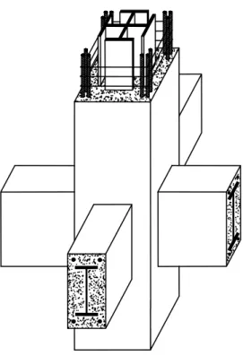
Figure 1 shows a typical layout of a SRC beam-to-column connection. A literature survey conducted by the authors indicated that past studies on the shear strength of SRC beam-to-column connection are very limited. It was found that a majority of past researches were focused on the steel beam-to-concrete filled tubular column (CFT) connections.
2. THE ACI-318 APPROACH
In the current ACI-318 code, the nominal shear strength Vnof a reinforced concrete beam-to-column connection can be determined as follows:
(a) For joints confined on all four faces
'
n c j
V =1.67 f A (1) (b) For joints confined on three faces or on two opposite faces
' n c j V =1.25 f A (2) (c) For others ' n c j V =1.0 f A (3) where ' c
f is the compressive strength of concrete in MPa; and A is the effective shear area at j the joint.
It has been known that the above equations are relatively conservative and maybe over-simplified. Furthermore, due to the existence of a steel section in the SRC column, it would not be appropriate to directly adopt these equations to predict the shear capacity of the SRC beam-to-column connection.
3. AN ALTERNATIVE APPROACH
This study develops a new analytical approach to estimate the shear strength of SRC beam-to-column connection. In general, the design shear strength φvVnof the SRC beam-to-column
connection is taken as the sum of the shear capacities of the steel section φvsVns and the accompanying reinforced concrete φvrc nrcV in the connection zone. That is
vV =n vsVns vrcVnrc
φ φ + φ (4)
where φvs=0.85 and φvrc=0.75.
The mutual beneficial correlation between the steel section and the reinforced concrete in the SRC joint is one of the important factors in developing the new design approach. It is noted that due to the protection of the reinforced concrete, the steel section embedded in the SRC connection is able to develop “shear yielding” in the ultimate state without premature failure caused by local buckling. Thus, the nominal shear strength of the steel section can be taken as
ns ys w
V =0.6f A (5) where fys is the yield strength of the steel section; and Awis the area of the web of the steel
section.
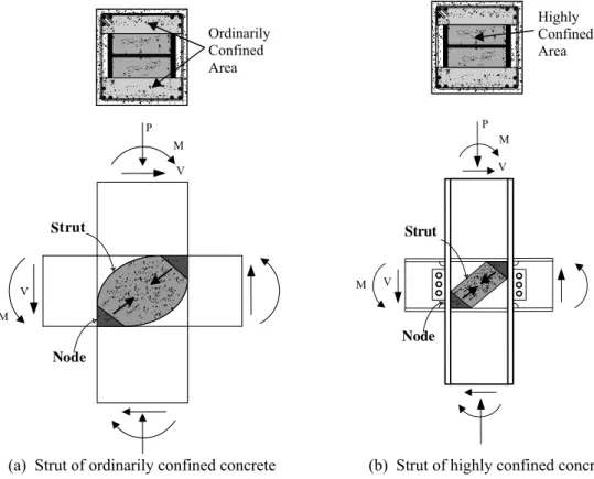
In addition, as shown in Fig. 2, in recognition of the superior confining effect provided by the steel section in the SRC column, the concrete within the column is sub-divided into two different zones, namely “the highly confined area” and “the ordinarily confined area,” so that the shear strengths of each part of the concrete can be predicted more rationally.
In this study, the strut-and-tie model is utilized to estimate the shear capacity of the reinforced concrete in the connection. Figures 3 (a) and (b) show the possible diagonal compressive struts in the SRC beam-to-column joint. The shear capacity of the reinforced concrete in SRC joint, Vnrc, is taken as the sum of the horizontal components of the capacities of the diagonal compressive struts of the “highly confined concrete” and the “ordinarily confined concrete” in the connection zone. That is
nrc hc oc
V =V +V (6) whereVhc and Vocare the shear capacities of the “highly confined concrete” and the “ordinarily
confined concrete” in the connection, respectively.
As shown in Fig. 4, in the highly confined area, it is possible for this part of concrete to remain sound without major cracking due to the protection the steel section in the SRC joint. Thus, by using the strut-and-tie model, the shear strength of the “highly confined concrete” can be approximated as the horizontal component of the maximum capacity of the compressive strut. It is further simplified as
( )
'( )
hc cc hc eff hc
V =0.85 f × A (7)
where
( )
' cc hcf is the compressive strength of the highly confined concrete considering the
beneficial confinement effect provide by the steel section and the hoop reinforcements; and
(Aeff)hcis the effective area of the highly confined concrete in the connection.
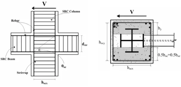
As shown in Fig.5, in the ordinarily confined area, it is more difficult for this part of concrete to remain sound in the ultimate state due to the absence of the confinement provided by steel section. However, it is noted that the shear strength of the “ordinarily confined concrete” is significantly influenced by the constraint provided by the surrounding SRC beams at the joint. Thus, by using the strut-and-tie model, the shear strength of the “ordinarily confined concrete” can be approximated as the horizontal component of the maximum capacity of the compressive strut. It is further simplified as
(a) For joints confined on all four faces
( )
'(
)
oc cc oc eff oc
V =0.85 f × A (8) (b) For joints confined on three faces or on two opposite faces
( )
'(
)
oc cc oc eff oc V =0.63 f × A (9) (c) For others( )
'(
)
= × (10)where
( )
' cc ocf is the compressive strength of the ordinarily confined concrete considering the beneficial confinement effect provide by the hoop reinforcements; and
(
Aeff oc)
is the effective area of the ordinarily confined concrete in the connection.It is found that the effective area of the “highly confined concrete”
(
Aeff hc)
can be expressed as(
Aeff)
hc=bcf×ahe (11)where bcf is the flange width of the steel column perpendicular to the shear direction; and
he
a is the effective depth of the highly confined concrete parallel to the shear direction.
hc hc
he ' ' hc hc hc
c cf cs c cf cs
M P
a 1 cos (cos sin ) 0.85f b h 0.85f b h
⎛ ⎞
= ⎜⎜ + ⎟⎟× θ θ + θ
⎝ ⎠ (12)
where Mhcand Phcare the bending moment and the axial force shared by the highly confined concrete, respectively; hcsis the depth of the steel column parallel to shear direction; and θhcis the angle between the horizontal shear force and the diagonal strut of the highly confined concrete.
Also, the effective area of the “ordinarily confined concrete”
( )
Aeff occan be expressed as(
Aeff)
oc =boe×aoe (13)where b is the effective width perpendicular to the shear direction; andoe a is the effective oe depth of the ordinarily confined concrete parallel to the shear direction. b and oe a can be oe found as follows:
(
)
(
)
oe bf y bf ocx cf
b =min b⎡⎣ +2b , b +h ⎤⎦−b (14) where b is the flange width of steel beam; and bf b is the distance from the edge of y steel beam flange to the center of hoop reinforcement parallel to the shear direction.
oc oc
oe ' ' oc oc oc
c oc ocx c oc ocx
M P
a 1 cos (cos sin )
0.85f b h 0.85f b h
⎛ ⎞
= ⎜ + ⎟× θ θ + θ
⎝ ⎠ (15)
where M and oc P are the bending moment and the axial force shared by the oc ordinarily confined concrete, respectively;b is the width of the ordinarily confined oc concrete perpendicular to shear direction; h is the depth of the ordinarily confined ocx concrete parallel to shear direction; and θ is the angle between the horizontal shear oc force and the diagonal strut of the ordinarily confined concrete.
4. CONCLUDING REMARKS
The proposed new approach is intended to provide an alternative method to predict the shear strength of the SRC beam-to-column connection. This study takes into account the composite nature of the SRC joint so that the interaction between the steel section and the reinforced
concrete in the connection zone can be treated more rationally. The mutual beneficial correlation between the steel section and the reinforced concrete in the SRC joint is one of the important factors in developing the new design approach. It is also hoped that this investigation will provide further insight on the understanding on the true mechanical behavior of the SRC beam-to-column connection.
5. REFERENCES
1. Weng, C.C., Yen, S.I. and Jiang, M.H.( 2002), Experimental Study on Shear Splitting Failure of Full-Scale Composite Concrete Encased Steel Beams. Journal of Structural
Engineering, ASCE, Vol. 128, No. 9, pp. 1186-1194.
2. Weng, C.C. and Yen, S.I. (2002), Comparisons of Concrete-Encased Composite Column Strength Provisions of ACI Code and AISC Specification. Engineering Structures, Vol. 24, No.1, pp. 59-72.
3. Wakabayashi, M.A. (1987), Historical Study of Research on Composite Construction in Japan. Proc. of Conf. on Composite Construction in Steel and Concrete, ASCE, New York, pp. 400-427.
4. AIJ (2001), Standards for Structural Calculation of Steel Reinforced Concrete Structures. Architectural Institute of Japan, Tokyo, Japan.
5. FEMA (1994), Recommended Provisions for the Development of Seismic Regulations for
New Buildings. FEMA-222A, National Earthquake Hazards Reduction Program, Building
Seismic Safety Council, Washington, D.C.
6. ACI (2005), Building Code Requirements for Structural Concrete (ACI 318) and
Commentary (ACI 318R). American Concrete Institute, Farmington Hills, Michigan.
7. AISC (2005), Load and Resistance Factor Design Specification for Structural Steel
Buildings. 4th Ed., American Institute of Steel Construction, Chicago, Illinois.
8. AISC (2002), Seismic Provisions for Structural Steel Buildings, American Institute of
Steel Construction, Chicago, Illinois.
9. ECCS (1994), Design of Composite Steel and Concrete Structures, Part 1.1: General
Rules and Rules for Buildings, ENV 1994-1-1: Eurocode 4, European Convention for
Constructional Steelwork.
10. MOI (2004), Building Code for Design of Steel Reinforced Concrete (SRC) Structures. Ministry of the Interior, Taiwan, Taipei (in Chinese)
Figure 2 “Highly confined concrete” and “ordinarily confined concrete” in SRC columns
Highly Confined Area Ordinarily Confined Area
Unconfined Area
Highly Confined Area
Ordinarily Confined Area
Unconfined Area
M P Strut Node M M V P Strut Node
Figure 3 Compressive strut of concrete in SRC beam-to-column joint
(a) Strut of ordinarily confined concrete (b) Strut of highly confined concrete
Ordinarily Confined Area Highly Confined Area
Figure 4 Highly confined area of concrete in the SRC joint
Highly Confined Concrete
V V