行政院國家科學委員會專題研究計畫 成果報告
漸變開槽饋入式超寬頻天線之小型化設計與分析
計畫類別: 個別型計畫
計畫編號: NSC93-2213-E-002-091-
執行期間: 93 年 08 月 01 日至 94 年 07 月 31 日
執行單位: 國立臺灣大學電信工程學研究所
計畫主持人: 鄭士康
報告類型: 精簡報告
報告附件: 出席國際會議研究心得報告及發表論文
處理方式: 本計畫可公開查詢
中 華 民 國 94 年 9 月 12 日
漸變開槽饋入式超寬頻天線之小型化設計與分析
Design and Analysis of Tapered-Slot-Fed Miniature
Antennas for Ultra-Wideband Applications
計畫編號
NSC93-2213-E-002-091
執行期限:93 年 8 月 1 日至 94 年 7 月 31 日
主持人:鄭士康 台大電信工程研究所
計畫參與人員:馬自莊, 鍾隆興, 黃俊達, 劉進豐
台大電信工程研究所
中文摘要 超寬頻技術(Ultra-wideband, UWB) 是近 年來最受曙目的通訊技術之一。此技術的基本 概念是直接傳送頻寬達數 GHz 的極短脈衝信 號。然而,要設計符合超寬頻技術應用的天線 卻不是容易的任務。此天線需同時達成寬頻的 阻抗,全向性場型,穩定的增益及線性的相 位,高輻射效率以及小型化設計。本研究計畫 提出一種新型漸變開槽餽入式超寬頻天線。此 天線係由一獨特之漸變開槽餽入結構與不同 之輻射體所組成。利用一個新推導出來的無因 次正規化天線轉移函數,此類天線的時域及頻 域獲得了完整的分析。而場型均勻度與信號保 真度的應用,更定量化的檢驗了天線的良窳。 本計畫亦將討論天線小型化的策略。 關鍵字:超寬頻技術,開槽天線,天線暫態分 析,天線輻射場型 AbstractUltra-wideband (UWB) technology has experienced a blooming growth in the past few years. The basic idea of this promising technology is to directly transmit and receive trains of extremely short baseband pulses that spread over bandwidth of several GHz. Generally speaking, it is quite challenging to design an antenna to simultaneously fulfill all the requirements in an UWB system, including ultra-wide bandwidth, omnidirectional patterns, constant gain and group delay over the entire band, high radiation efficiency and low profile. In this project, a novel category of ultra-wideband antenna topology is proposed and investigated. This new class of antennas utilizes a unique tapered-slot feeding structure and various radiating elements to fulfill the needs of UWB antennas . By means of a dimensionless normalized antenna transfer
function, both frequency domain and time domain characteristics of these antennas are investigated. Two measures, the uniformity related to the radiation patterns and the fidelity associated with the transient behaviors, are used to quantitatively describe the performance of such antennas over an ultra-wide bandwidth. The effects of further minimizing the antenna dimension is discussed as well.
Keywords: Ultrawideband antennas, slot antennas, antenna transient analysis, antenna radiation patterns
I. Introduction
The demands for high-speed, high-capacity, low-cost indoor wireless communications have been raised rapidly in recent years. While the IEEE 802.11a/b/g/n standards are proposed for the wireless local-area networks (WLANs), the IEEE 802.15.3a standard is now developed to fulfill the needs of wireless personal-area networks (WPANs). The WPANs, mainly serving as cable eliminators in personal multimedia equipments, complement the WLANs to satisfy the diverse requirements in indoor wireless applications.
Among those techniques proposed for WPANs, the ultrawideband (UWB) technology has experienced a blooming growth in the past few years. It inherently possesses high-speed data rates, excellent immunity to multipath interference, low power consumption, and reduced hardware complexity. In 2002, the Federal Communication Commission (FCC) in United States officially released the regulations for UWB technology, and the spectrum from 3.1 to 10.6 GHz is allocated for unlicensed UWB communication applications. The antenna implemented in an UWB system plays a more unique role than it does in other systems [1]-[2]. In such a system, the antenna behaves like a bandpass filter and reshapes the spectra of the
pulses. It needs to be designed with care to avoid undesired distortions. Generally speaking, it is quite challenging to design a suitable antenna to fulfill all the critical requirements of UWB radios, including ultra-wide bandwidth, omnidirectional patterns, constant gain and group delay over the entire band, high radiation efficiency and low profile.
In this project, a new class of planar antennas with a novel feeding structure is developed. This kind of antennas utilizes a wideband tapered-slot feeding structure and various radiating elements to fulfill the needs of UWB antennas [3]-[4]. In this report, one of such antennas, the tapered-slot-fed annular slot antenna, will be investigated in more detail. With the help of a newly proposed dimensionless normalized antenna transfer function, the frequency domain as well as the time domain antenna characteristics have been carefully investigated. Two measures, the uniformity associated with the radiation patterns and the fidelity related to the transient properties, are adopted to quantitatively describe the performances of UWB antennas in both frequency and time domains. Some observation to further minimize the antenna size is discussed at the end of this report.
II. Antenna Configuration and Performance
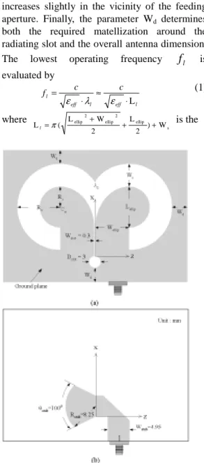
The geometry of the proposed antenna with its parameters is depicted in Fig. 1. The energy is first transferred from the microstrip line to the slotline by a wideband transition. The tapered-slot feeding structure then serves as an impedance transformer and guides the wave propagating from the slotline to the radiating slot without causing pernicious reflection. The radiating slot is then curved to distribute part of the energy to the reverse side of the feeding aperture. It therefore forms a tapered-slot-fed annular slot antenna. The geometry of this antenna can be mainly determined by four parameters: Lellip, Wellip, Ws, and Wd. The tapered
profile of the feeding structure is described by an equation of an ellipse with the semi-major and semi-minor axes equaling Lellip and Wellip,
respectively. The inner boundary of the annular slot is described by this elliptical profile and a semicircle centered at Cs. The radius of this
semicircle is fixed to half of the semi-major axis of the elliptical profile, i.e. Ri = Lellip/2. The
outer boundary of the annular slot is depicted with an arc that intersects the midline of the antenna at Ao. This arc is co-centered at Cs with
radius Ro = Lellip/2+Ws. The width of the annular
slot Ws is constant along the concentric arcs and
increases slightly in the vicinity of the feeding aperture. Finally, the parameter Wd determines
both the required matellization around the radiating slot and the overall antenna dimension. The lowest operating frequency
f
l is evaluated by l eff l eff l c c f L ⋅ ≈ ⋅ = ε λ ε (1) where s ellip 2 ellip 2 ellip W ) 2 L 2 W L ( Ll=π + + + is theFig. 1 Geometry of the antenna. (a) Top layer (b) bottom layer.
approximated longest current path along the inner boundary of the annular slot. The highest operating frequency
f
u of the antenna isrelated to that of the wideband transition. After determining the operating bandwidth, the matellization around the antenna is adjusted to minimize the required dimension while preserving the impedance bandwidth.
Two versions of the proposed antenna, the reference antenna and the miniature antenna, were designed on a Rogers RT/Duroid 5880 substrate with h = 1.57 mm and
ε
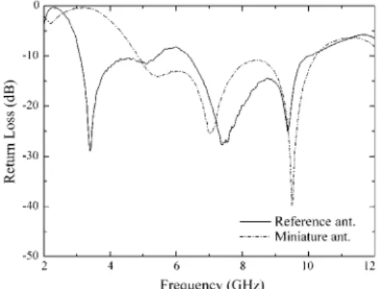
r = 2.2. The dimensions of the reference and miniature antennas are 46.5 by 66.3 mm2 and 35.6 by 40.3 mm2, respectively. The measured return losses of the antennas are depicted in Fig. 2. Theoperating bandwidth of the reference antenna with |S11| < -9.5 dB (or VSWR < 2) covers
almost the whole allocated UWB spectrum from 3.1 to 10.6 GHz. The miniature antenna, a miniaturized version of the proposed antenna, operates from 4.8 to 10.2 GHz.
Fig. 2 Measured return losses of the antennas
III. Frequency Domain Characteristics
Shown in Figs. 3 (a) and (b) are the representative measured radiation patterns of the reference antenna at 6.5 GHz in both E and
H-planes, respectively. In order to achieve a
more comprehensive understanding of the radiation patterns, we also adopt the definition of uniformity to quantitatively describe the performance of the radiation patterns as
21, max max ( ) Uniformity( )f =P( |S AUT(θ φ, ) |dB 21, ( ) |S AUT( , ) |θ φ dB 6dB )( )f − ≤ (2) In (2), |S21,AUT(θ,φ)| is the measured radiation pattern of the antenna under test (AUT) at a specific plane cut and frequency, and
) ,
(
θ
maxφ
max is the direction where maximumradiation occurs. To experimentally evaluate the uniformity the radiation patterns were measured in an anechoic chamber from 1 to 18 GHz with a 0.02125 GHz step. The spatial angle steps with a 0.9° interval. This corresponds to a two-dimensional sampling of 801 frequency points by 400 spatial points. Figure 4 illustrates the uniformity of the reference and miniature antennas in H-plane from 2 to 12 GHz.
The antenna transfer functions are another issue of concern, from which we can judge to what extent the spectra of the pulses will be modified by the antenna. In this project we propose a new dimensionless normalized antenna transfer function
{
}
4 ( , , ) ( , , ) N N H f θ φ π h tθ φ λ = ℑ , (3)Fig. 3 The radiation patterns at the center frequency of UWB band
Fig. 4 The uniformity of the antennas. which can be evaluated directly from the modified two-antenna gain measurement method. In (3), h tN( , , )
θ φ
is the normalized antennaimpulse response. The overall response of a transceiving antenna system can be readily achieved using this transfer function as well,
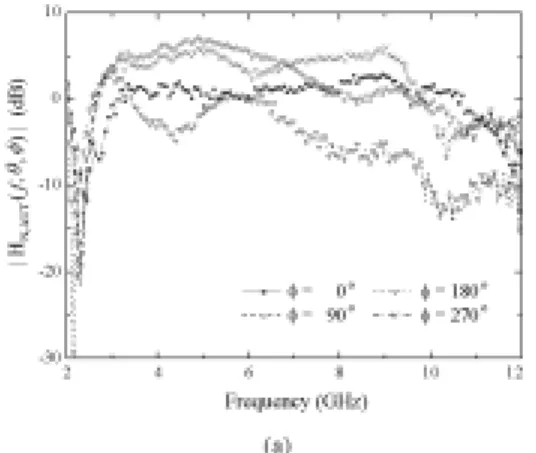
c f j Rx N Tx N f H f e H j f S R 2 , , 21 ( , , ) ( , , ) R 4 ) ( θ φ θφ π π λ − = . (4) Figure 5 illustrates the magnitude of the normalized antenna transfer functions of the reference antenna at
φ
=
0°, 90°, 180°, 270° inH-plane. Figure 6 then compares the measured
and calculated overall responses as the antenna pairs being aligned face-to-face. Reasonable agreements between the results can be observed
IV. Time Domain Characteristics
Time domain antenna properties are investigated using the normalized antenna transfer functions in Section III. As the incident wave arriving at the receiving antenna being the fourth derivative of a Gaussian function, the output waveform at the receiving antenna terminal can be expressed by
.
Fig. 5 Magnitudes of the antenna transfer functions.
Fig. 6 Comparisons of the calculated and measured overall response.
{
}
1 , ( , , ) ( ) ( , , ) ( ) r i N RX s tθ φ = ℑ− S f ⋅H f θ φ ⋅ ∏ f (5) where∏
( f
)
represents an ideal bandpass filter from 1 to 18GHz. The received pulses are then correlated with a template pulses
t(t
)
for pulse detections. A well-defined parameter named fidelity has been proposed to evaluate the capability of pulse detection of an antenna,Fig. 7 The fidelity of the antennas.
+ =
∫
∫
∫
∞ ∞ − ∞ ∞ − ∞ ∞ − dt t s dt t s dt t s t s Fidelity r t r t ) , , ( ) ( ) , , ( ) ( max ) , ( 2 2 θ φ φ θ τ φ θ τ (6) The fidelity in (6) is in essence the correlation coefficient of the template and received pulses. Figure 7 shows the fidelity of the reference and miniature antennas in H-plane with the template pulse being the same ass
i(t
)
. It validates thatthe reference antenna does not distort the incident pulse significantly.
V. Discussion
The performance of the miniature antenna was also investigated. As mentioned in Section II, the impedance bandwidth of this antenna does not cover the whole allocated UWB spectrum. However, it is noticed that apart from the fact that the uniformity and fidelity of the miniature antenna are also generally lower than those of the reference antenna, they still remain acceptable. The reason can be explained as follows. Due to the insufficient impedance bandwidth of the miniature antenna, it inevitably introduces more distortions to the incident pulses. However, as long as the operating band of this antenna covers the spectrum in which the pulse energy concentrates, the antenna performance can be mostly preserved. With this observation, further miniaturizing the antenna dimension to add flexibility in circuit integration can be readily achieved.
References
[1]K. L. Wong, C. H. Wu and S. W. Su, “Ultrawideband square planar metal-plate monopole antenna with a trident-shaped feeding strip,” IEEE Trans. Antennas Propagat., vol. 53, pp. 1262-1269, Apr. 2005.
[2] Z. N. Chen, “Novel bi-arm rolled monopole for UWB applications,” IEEE Trans.
Antennas Propagat., vol. 53, pp. 672-677, Feb.
2005
[3] T. G.. Ma and S. K. Jeng, “Planar miniature tapered-slot-fed annular slot antennas for ultra-wideband radios,” IEEE Trans.
Antennas Propagat, Vol. 53, pp. 1194-1202, Mar.
2005.
[4] T. G. Ma and S. K. Jeng, “A tapered-slot-feed loop antenna for ultra-wideband applications,” in
Proc. Joint UWBST & IWUWBS 2004, May