國立交通大學
電子工程學系 電子研究所碩士班
碩 士 論 文
新的時間同步演算法應用於3GPP LTE Downlink細胞搜索
A New Timing Synchronization Algorithm in Cell Search for 3GPP
LTE Downlink
研 究 生 : 蔡 耀 賢
指導老師 : 桑 梓 賢 教授
新的時間同步演算法應用於 3GPP LTE Downlink 細胞搜索
A New Timing Synchronization Algorithm in Cell Search for 3GPP
LTE Downlink
研 究 生 : 蔡耀賢 Student : Yao-Hsien Tsai
指導教授 : 桑梓賢 教授 Advisor : Tzu-Hsien Sang
國 立 交 通 大 學
電子工程學系 電子研究所碩士班
碩 士 論 文
A Thesis
Submitted to Department of Electronics Engineering & Institute of Electronics College of Electrical and Computer Engineering
National Chiao Tung University In Partial Fulfillment of the Requirements
for the Degree of Master of Science
in
Electronics Engineering Feb 2011
Hsinchu, Taiwan, Republic of China
新的時間同步演算法應用於3GPP LTE Downlink細胞搜索
研究生:蔡耀賢 指導教授:桑梓賢 教授
國立交通大學
電子工程學系 電子研究所碩士班
摘要
在長期演進技術(LTE)系統下,我們提出一個好的時間同步方法和初始細胞搜索流 程。初始細胞搜索流程主要分成四個步驟,第一步驟必須將接收端所接收到的訊號,經 過低通濾波器將同步訊號以外的資料濾掉;第二步驟執行時間同步,利用第二同步訊號 的共軛對稱,對載波頻率偏差較不敏感的特性,可以提高時間同步的準確性,找出第二 同步訊號的起始點;第三步驟利用找到的第二同步訊號的起始點,經過結合循環字首盲 檢測與主同步訊號偵測得到主同步訊號的位置和細胞第二編號 ( (2) ID N ),並解決載波頻率 偏移問題,第四步驟則是利用所得到的細胞第二編號進行第二同步訊號的偵測,得到細 胞第一編號( (1) ID N ),藉由結合第一編號與第二編號,可以得到完整的細胞編號,細胞搜 索也就此完成。 關鍵字: 細胞搜索、同步、長期演進技術A New Timing Synchronization Algorithm in Cell Search for
3GPP LTE Downlink
Student:Yao-Hsien Tsai Advisor:Tzu-Hsien Sang
Department of Electronics Engineering & Institute of Electronics
National Chiao Tung University
ABSTRACT
The invent is a method of a new timing synchronization method and 3rd Generation Partnership Project (3GPP) Long Tern Evolution (LTE) cell search procedure is proposed. The procedure can be divided into four steps. Firstly, received signal has passed a low-pass filter to remove other data which are not synchronization signals. Secondly, timing synchronization is performed by Secondary synchronization signal’s conjugate symmetry that is immune to carrier frequency offsets (CFO). The property can raise the timing synchronization accuracy. Thirdly, in time or in frequency domain, use detected SSS starting position and perform joint of blind cyclic prefix (CP) detection and primary synchronization signal (PSS) detection to find out CP length, PSS position, and NID(2). The CFO problem can be also solved in this step. Finally, secondary synchronization signal (SSS) detection is adopted. After going through procedure we can get physical-layer cell identity (Cell-ID) and cell search is accomplished.
誌 謝
首先誠摯的感謝指導教授桑梓賢 博士,老師悉心的教導及不時的討論並指點我正 確的方向,使我在這些年中獲益匪淺。再來要感謝我的口試委員林大衛教授、薛木添教 授,各位老師在口試時對於我的指導,更讓我發現本論文主題可以更深入探討的地方, 並給予多方的建議,使這篇論文更為完善。 兩年裡的日子,實驗室裡共同的生活點滴,學術上的討論、言不及義的閒扯、讓人 又愛又怕的宵夜、趕作業的革命情感...,感謝眾位學長姐、同學、學弟妹的共同砥 礪,你/妳們的陪伴讓兩年的研究生活變得絢麗多彩。感謝欣德學長、宗達學長、哲聖 學長、譯賢學長與CommLab實驗室的學弟與學長們不厭其煩的幫助,且總在我迷惘時為 我解惑,也感謝俊育同學、旭謙同學們的陪伴,恭喜我們順利走過這兩年半。當然也不 能忘記實驗室的建志學弟、建宏學弟、胤宏學弟、碩文學弟、柔綾學妹們的幫忙。 最後要感謝我的家人與女友,這段時間一直在忙學業的問題,與家人相處的時間很 少,因為爸媽與的體諒與支持鼓勵,才能專心完成學業;女友平時的陪伴與打氣,也適 時緩和我的壓力,另外還有很多曾經幫助過我的朋友,因為有大家的幫助與打氣,我才 能順利完成碩士學位。 蔡耀賢 謹誌 2011年2月Contents
中文摘要 ... i 英文摘要 ... ii 誌謝 ... iv 目錄 ... v 圖目錄 ... vi 表目錄 ... vi Chapter 1 Introduction ... 11.1.1 Primary Synchronization Signal ... 2
1.1.2 Secondary Synchronization Signal ... 4
Chapter 2 Synchronization and Cell Search Procedure ... 6
2.1 System Model ... 6
2.2 Synchronization and Cell Search Procedure ... 7
2.2.1 Timing Synchronization and FCFO Compensation ... 7
2.2.2 Three PSS Correlation ... 7
2.2.3 PSS Self-symmetry Correlation ... 8
2.2.4 SSS Self-symmetry Correlation ... 9
2.3 Joint Of PSS Detection and ICFO Compensation ... 10
2.3.1 In Time Domain ...10
2.3.2 In Frequency Domain ...10
2.4 SSS Detection ... 11
2.5 Joint Of Cell Search Procedure and CP Length Detection ... 12
Chapter 3 Simulation Results and Summary ... 14
3.1 Simulation Result ... 14
3.2 Summary ... 18
List of Figures
Fig.1.1 LTE frame structure for FDD (normal cyclic prefix). ... 2
Fig. 1.2 PSS sequence withNID(2)is 0 after 128-point IDFT in the time domain. ... 3
Fig. 1.3 SSS sequence withNIDCellis 0 after 128-point IDFT in the time domain. ... 5
Fig. 2.1 Synchronization and cell search procedure. ... 8
Fig. 2.2 Block diagram of SSS detection ... 11
Fig. 2.3 Joint of cell search procedure and CP length detection ... 12
Fig. 3.1 Timing synchronization in terms of the MSE measured in samples against the SNR. ... 15
Fig. 3.2 PSS detection performance for NID(2)in time domain. ... 16
Fig. 3.3 PSS detection performance forNID(2)in frequency domain... 17
Fig. 3.4 Detection performance for NIDcell ... 18
List of Tables
Table I. Tapped delay-line parameters ... 14Chapter 1
Introduction
The LTE is a mobile communication standard proposed by 3GPP. LTE is designed to meet carrier needs for high speed data rate and media transport as well as high capacity voice support into the next decade. Multiple-input and multiple- output (MIMO) technique and bigger broad bandwidths are used. LTE adopts different transmission types in uplink and downlink. Single Carrier Frequency Division Multiple Access (SC-FDMA) is employed for uplink data transmission and Orthogonal Frequency Division Multiplexing (OFDM) is used for downlink data transmission. The system supports both Time Division Duplexing (TDD) and Frequency Division Duplexing (FDD), flexible bandwidths from 1.4 to 20 MHz depending on systems need.
The frame structure for FDD is shown in Fig. 1.1 Downlink data transmission is arranged in frames whose duration is 10ms. Each frame consists of ten 1ms subframes, each subframe is defined as two consecutive 0.5ms slots [1].
At the initial power-up of user equipment (UE), the UE must perform synchronization and cell search to acquire Cell-ID. It is known that ODFM systems are sensitive to time and frequency errors. Hence it is necessary to have robust synchronization to derive correct Cell-ID and provide reliable service. Our goal is to develop a new timing synchronization algorithm and cell search procedure such that the impact of time and frequency errors is minimized.
Fig.1.1 LTE frame structure for FDD (normal cyclic prefix).
1.1 LTE Synchronization Signals
Cell-ID is derived from physical layer cell identity group, NID(1) (in the range of 0 to
167) and physical layer identity within the cell-identity group NID(2) (in the range of 0 to 2).
According to LTE specification, there are 504 physical-layer cell identities transmitted in synchronization channel (SCH) [1]. The SCH is split into Primary synchronization channel (P-SCH) and Secondary synchronization channel (S-SCH). Both synchronization sequences are mapped on 62 subcarriers located around the DC-subcarrier in frequency domain. In FDD mode, P-SCH is transmitted with the last OFDM symbol in time slot 0 and time slot 10 (every 5ms). S-SCH is transmitted with the second-last symbol in time slot 0 and time slot 10 as shown in Fig. 1.1
1.1.1 Primary Synchronization Signal
The PSS sequence pu(n)is generated from a frequency domain Zadoff-Chu sequence according to ⎪ ⎩ ⎪ ⎨ ⎧ = = = + + − + − 61 ,..., 32 , 31 30 ,..., 1 , 0 ) ( 63 ) 2 )( 1 ( 63 ) 1 ( n e n e n p n n u j n un j u π π (1)
For the same indexu, Zadoff-Chu sequence has ideal periodic auto-correlation property.
For the different indexu , Zadoff-Chu sequences are not orthogonal, but have low
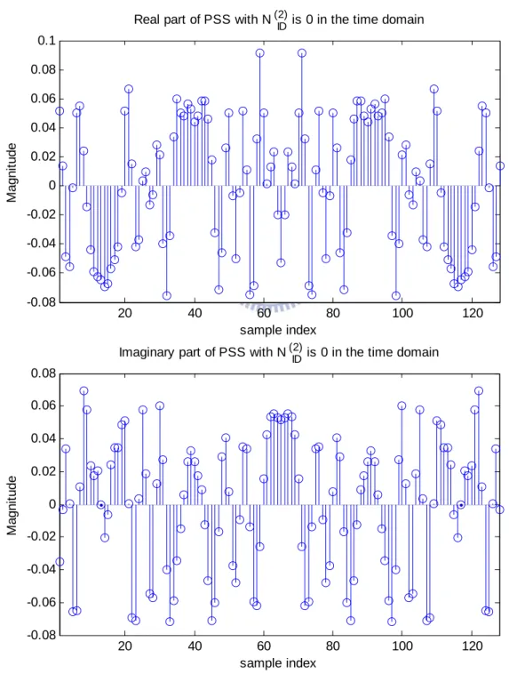
cross-correlation [2]. On the other hand, The PSS sequence after Inverse Discrete Fourier Transform (IDFT) will exhibit self-symmetric property. The real part and imaginary part of PSS are both symmetric.
There is an example that PSS sequence withNID(2)is zero as shown in Fig. 1.2 The real part and imaginary part of PSS is even symmetry by the middle point.
20 40 60 80 100 120 -0.08 -0.06 -0.04 -0.02 0 0.02 0.04 0.06 0.08 0.1
Real part of PSS with N (2) ID is 0 in the time domain
M a gni tude sample index 20 40 60 80 100 120 -0.08 -0.06 -0.04 -0.02 0 0.02 0.04 0.06 0.08
Imaginary part of PSS with N (2) ID is 0 in the time domain
sample index Ma g n it u d e
1.1.2 Secondary Synchronization Signal
The SSS sequence is interleaved by two length-31 binary sequences [1]. The combination of two length-31 sequences differs between slot 0 and slot 10 according to
⎪⎩ ⎪ ⎨ ⎧ = 10 slot in time ) ( ) ( 0 slot in time ) ( ) ( ) 2 ( 0 ) ( 1 0 ) ( 0 1 0 n c n s n c n s n d m m (2) ⎪⎩ ⎪ ⎨ ⎧ = + 10 slot in time ) ( ) ( ) ( 0 slot in time ) ( ) ( ) ( ) 1 2 ( 1 0 0 1 1 1 ) ( 0 1 1 ) ( 1 n z n c n s n z n c n s n d m m m m (3) where m and 0 m1 are derived from
) 1 (
ID
N , so if we acquire m and 0 m1 that imply ) 1 ( ID N is known.
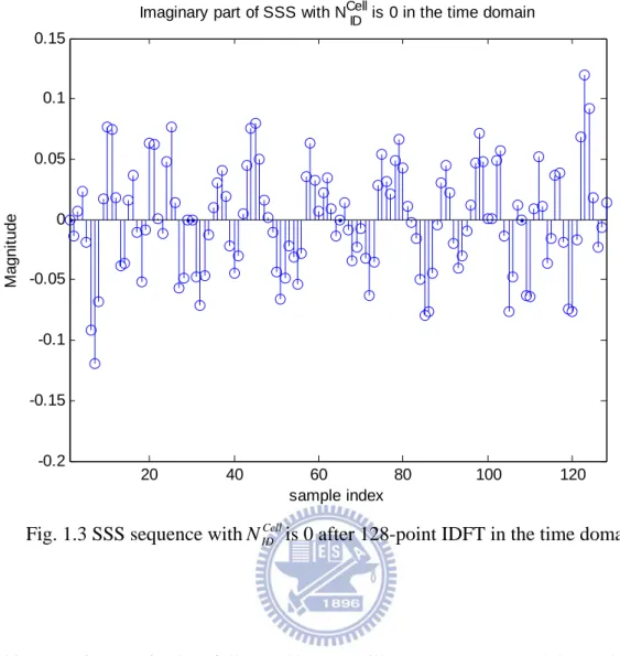
The SSS sequence, since it is real-valued in the frequency domain, after Inverse Discrete Fourier Transform (IDFT) it will be conjugate symmetric; this is different from PSS. There is an example that SSS sequence with NIDCellis zero as shown in Fig. 1.3. Different from PSS,
the real part of SSS is even symmetry, but imaginary part of SSS is odd symmetry by the middle point. 20 40 60 80 100 120 -0.1 -0.08 -0.06 -0.04 -0.02 0 0.02 0.04 0.06 0.08
Real part of SSS with NCell ID is 0 in the time domain
sample index Ma g n it u d e
20 40 60 80 100 120 -0.2 -0.15 -0.1 -0.05 0 0.05 0.1 0.15 Ma g n it u d e sample index
Imaginary part of SSS with NCell ID is 0 in the time domain
Fig. 1.3 SSS sequence withNIDCellis 0 after 128-point IDFT in the time domain.
This paper is organized as follows. Chapter 2 illustrates system model, synchronization and cell search procedure. Finally, Simulation results and summary are given in Chapter 3.
Chapter 2 Synchronization and Cell
Search Procedure
2.1 System Model
Data transmission in LTE Downlink uses OFDM, and the transmitted signal denoted ) (n s is given by e n N N n s N N N kn j k ≤ ≤ =
∑
− − 1 , 1 ) ( 1 2 / 2 / ) 2 ( π α (4) where αk denotes the data on the k subcarrier and th Nis the IDFT size. Transmitting over a multipath propagation channel and consideration of carrier frequency offset (CFO) due to misalignment oscillators between transmitter and receiver, the received signal with additive white Gaussian noise (AWGN) and cyclic prefix is given by
[
]
) 2 ( ) ( ) ( ) ( ) ( N n j e n w n h n s n r πε + ∗ = (5)where h(n)is channel impulse response,w(n)is noise, ∗ denotes linear convolution andε is the CFO, which is frequency mismatch normalized by the subcarrier spacing.
Channel impulse response can be model as
∑
− = − = 1 0 ) ( ) ( d N d d n d h n h δ (6) where dis delay time, h is the complex number of Rayleigh-distributed tap reference to d2.2 Synchronization and Cell Search Procedure
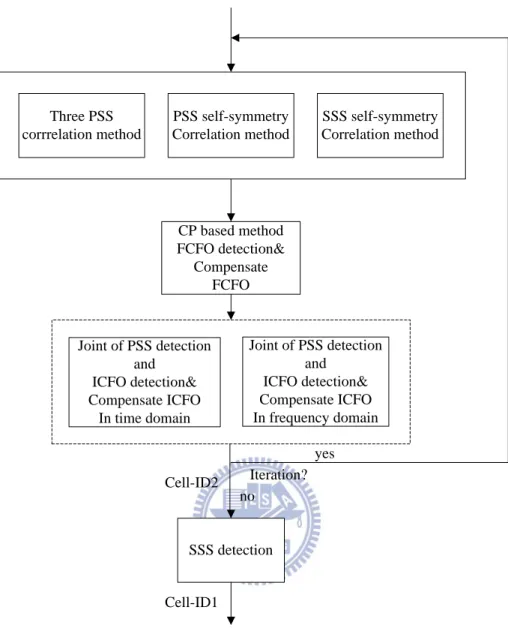
The synchronization and cell search procedure is shown in Fig. 2.1. The CP length assumed known. The received signal is sampled at 30.72MHz and is of 20MHz channel bandwidth, and the synchronization sequences occupy the 72 subcarriers in middle part with their own bandwidth of 1.08MHz. Therefore received signal is first passed through a low-pass filter, then down-sampled to 1.4MHz to fit 128-points IDFT for reducing computational complexity.
2.2.1 Timing Synchronization and FCFO Compensation
The major goal of timing synchronization is to acquire accurate OFDM symbol timing. To our knowledge, there are three methods to detect the position the time location of PSS. The last one is our proposed algorithm. Good synchronization will improve the accuracy of the Cell-ID detection. We will first introduce the three methods.
2.2.2 Three PSS Correlation
The three specified PSS sequences denoted pu(n), where uis 25, 29 and 34 according to three P-SCH signals, is cross-correlated with the received signal denoted r(n)according to
∑
− = ∗ + + = 1 0 ) ( ) ( ) ( N m u u n p n m r n m Q (7)where N denote FFT size, measured in time samples. The starting position of P-SCH is
estimated by detecting the peak ofQu(n) , andNID(2)is determined by ( ˆ ,ˆ) argmax
(
( ))
, ) 2 ( n Q n N u n u ID = (8)where nˆis the estimated P-SCH start position and NˆID(2)is estimated physical layer identity
PSS self-symmetry Correlation method CP based method FCFO detection& Compensate FCFO SSS detection SSS self-symmetry Correlation method Three PSS corrrelation method Joint of PSS detection and ICFO detection& Compensate ICFO In frequency domain Joint of PSS detection and ICFO detection& Compensate ICFO In time domain Cell-ID2 Cell-ID1 Iteration? yes no
Fig. 2.1 Synchronization and cell search procedure.
2.2.3 PSS Self-symmetry Correlation
The symmetry of PSS can be exploited to the purpose of timing synchronization. Like the well-known CP-based method to detect symbol timing, we can use the PSS inherent symmetry to detect its start position.
The received signal first goes through an auto-correlation operation:
∑
− = ∗ − + + = /2 1 1 ) ( ) ( ) ( N m N m n r m n r n Q (9)where N denote FFT size, measured in time samples. The starting position of P-SCH is
estimated by
(
( ))
max arg ˆ Q n n n pss = (10)2.2.4 SSS Self-symmetry Correlation
The SSS in time domain shows conjugate symmetry. Even through its name implies it is secondary in the synchronization procedure, we found that its structure is advantageous to be sued in the first step of synchronization. The received signal goes through a slightly different cross-correlation:
∑
− = + − + = /2 1 1 ) ( ) ( ) ( N m N m n r m n r n Q (11)where N denote FFT size. The starting position of S-SCH is then estimated by
(
( ))
max arg ˆ Q n n n sss = (12)where nˆsssrepresent the estimated S-SCH start position. The P-SCH position is at the next
symbol time for FDD frame structure.
The computing complexity of the three methods is as follows. Let the length of received
signal is L and the IDFT size is N . Method one needs 3×(L−N+1)×N complex
multiplications; Method two and method three need (L−N +1)×(N/2−1) complex multiplications.
Then we show that Method Three is quite resistant to CFO. Denote the received signal with CFO in AWGN channel is
, 0,1,..., 1 2 − = =x e k N y N k j k k πε (13)
where x is PSS sequence or SSS sequence, depending whether in method two or method k
three. ε is the CFO and Nis the IDFT size. At the output of correlator of (9) and (11), we acquire QpssandQsss given by
N j N N j N N N j N N j pss e x e x e x e x Q ) 2 ( 2 2 1 ) 2 / ( ) 4 ( 2 2 2 ) 2 / ( ) 4 ( 2 2 2 ) 2 ( 2 2 1 ... πε πε πε πε − − − − + + + + = (14)
(
2)
1 ) 2 / ( 2 2 ) 2 / ( 2 2 2 1 ) ( 2 ) ( 2 2 1 ) 2 / ( ) ( 2 2 2 ) 2 / ( ) ( 2 2 2 ) ( 2 2 1 ... ... − − − − + + + + = + + + + = N N N N j N N j N N N j N N N j N N j sss x x x x e e x e x e x e x Q πε πε πε πε πε (15)In (14), the interference caused by CFO will influence the accuracy of the judgment. While in (15), it is clear that the detector is quite immune to CFO. The simulation comparison will be shown in Chapter 3.
After the initial timing synchronization, CFO is estimated and compensated. CFO can be separated into the integer part and the fractional part as follows
f i ε
ε
ε = + (16) where εiis integer number of subcarrier spacing and εf is fractional part with value in
1 1< <
− εf . We can use CP-based methods, such as in [3], to acquire fractional CFO.
2.3 Joint Of PSS Detection and ICFO Compensation
The major goal of PSS detection is to detect physical layer identity within the cell-identity groupNID(2). ICFO detection can be jointly estimated in this process. There are two methods can be used, depending on in what domain we handle the problem.
2.3.1 In Time Domain
In order to findNID(2), the three PSS sequences in time domain are cross-correlated with
the received P-SCH symbol. The correlation equation is given by
u N n N n j pss u I u y n e p i i ⊗ ⎟⎟ ⎠ ⎞ ⎜⎜ ⎝ ⎛ = Φ
∑
− = ≤ ≤ = 1 0 ) 2 ( , 34 , 29 , 25 ) ( max arg ) ˆ , ˆ ( πε β ε β ε (17)whereypssdenote the received P-SCH symbol, p denote three known PSS time-domain u
sequences, uis 25, 29 and 34 according to threeNID(2) is 0, 1, 2. Theεidenote ICFO,βis ICFO range and⊗denotes circular correlation.
2.3.2 In Frequency Domain
The three PSS sequences in frequency domain are cross-correlated with the received P-SCH symbol. The correlation equation proposed by [4] is given by
) ( ) 1 ( ) ( ) 1 ( max arg ) ˆ , ˆ ( * * 61 1 , 34 , 29 , 25 k P k P k Y k Y u pss i pss i u u k u I i + − − + = Φ
∑
= ≤ ≤ = ε ε ε β ε β (18) where Ypssdenote received P-SCH symbol transformed in frequency domain,P denote three uknown PSS frequency-domain sequences, uis 25, 29 and 34 according to threeNID(2) is 0, 1,
2. Theεidenote ICFO,βis ICFO range.
Due to this differential operation, the detector is immune to symbol timing error and channel phase response, the demonstration is shown in [4] and [5].
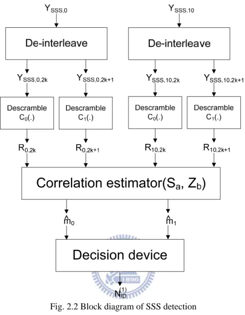
Fig. 2.2 Block diagram of SSS detection
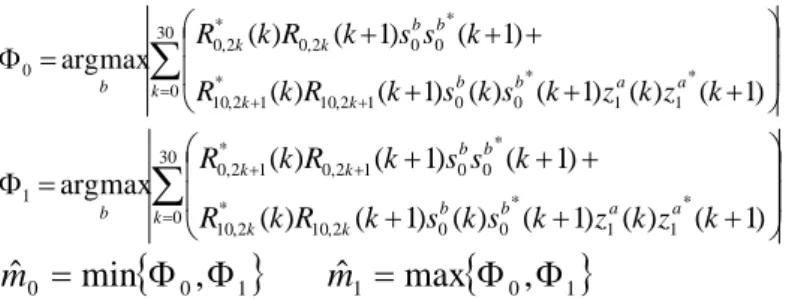
2.4 SSS Detection
After timing synchronization and frequency synchronization, NID(2)has been acquired, and the Cell-ID can be obtained. A common SSS detection method is proposed in [4] and is shown in Fig. 2.2, where Ysss,0denotes the received time slot-0 SSS sequence transformed in the frequency domain, andYsss,0denotes the time slot-10 SSS sequence.
SSS detection method consists of following steps. First, separate Ysss,0 into R0,2kand
1 2 , 0 k+
R , consisting of odd and even subcarriers respectively. Similarly separate Ysss,10 into
k
R10,2 an R10,2k+1 . Second, R0,2k , R0,2k+1 , R10,2k and R10,2k+1 are descrambled by
1 0, c
∑
= + + ⎟ ⎟ ⎠ ⎞ ⎜ ⎜ ⎝ ⎛ + + + + + + = Φ 30 0 * 1 1 * 0 0 1 2 , 10 * 1 2 , 10 * 0 0 2 , 0 * 2 , 0 0 ) 1 ( ) ( ) 1 ( ) ( ) 1 ( ) ( ) 1 ( ) 1 ( ) ( max arg k b b a a k k b b k k b R kR k s ks k z kz k k s s k R k R∑
= + + ⎟ ⎟ ⎠ ⎞ ⎜ ⎜ ⎝ ⎛ + + + + + + = Φ 30 0 * 1 1 * 0 0 2 , 10 * 2 , 10 * 0 0 1 2 , 0 * 1 2 , 0 1 ) 1 ( ) ( ) 1 ( ) ( ) 1 ( ) ( ) 1 ( ) 1 ( ) ( max arg k b b a a k k b b k k b R k R k s k s k z k z k k s s k R k R{
0 1}
0 min , ˆ = Φ Φ m mˆ1 =max{
Φ0,Φ1}
(19) where 0≤ b≤30and0≤ a≤7 s0bandz1aare cyclic shift version of s0(m=0)anz1(m=0). Accordingto LTE specificationm1is always larger thanm , and once0 m1andm are detected, 0 NID(1)can be identified. The overall Cell-ID (NIDcell)is equal toNIDcell =3NID(1) +NID(2).
2.5 Joint Of Cell Search Procedure and CP Length
Detection
The Chapter 2.2 to 2.4 introduces the different cell search procedures in the situation that CP length is previous known. The blind CP length detection can refer [10]. In this Chapter we add blind CP length detection in the cell search procedure as shown in Fig. 2.3.
Fig. 2.3 Joint of cell search procedure and CP length detection
Step 1 and Step 4 are the same as before. In step 2, we have to perform SSS self-symmetry correlation to find the starting position of S-SCH. After finding the starting position we decide to judge the CP length and Cell-ID2. In FDD mode, the P-SCH is just in the next symbol. So we can find starting position of P-SCH by
sss normal CP pss N N n nˆ (0)= , + + ˆ (20) sss extended CP pss N N n nˆ (1)= , + + ˆ (21) Where NCP,normaldenotes normal CP length, NCP,extendedis extended normal CP length, N is IFFT size length, nˆ represents estimated S-SCH starting position of the symbol, and sss nˆpssis
the estimated starting position of P-SCH of the symbol.
In Step 3, take two PSS symbols according to two type CP length and apply correlation computation in the time domain or in the frequency domain. CP length, physical-layer identity within the physical-layer cell identity group (NID(2)) and integer carrier frequency offset (ICFO) will be acquired.
In the time domain:
u N n N n j m pss u m I u m y n e p I I ⊗ ⎟⎟ ⎠ ⎞ ⎜⎜ ⎝ ⎛ = Φ
∑
− = ≤ ≤ = = 1 0 ) 2 ( , , 34 , 29 , 25 , 1 , 0 ) ( max arg ) ˆ , ˆ , ˆ ( πε β ε β ε (22) pssy is PSS symbol in the time domain, mdenotes different CP types, m=0represent using normal CP and m=1represent using extended CP. p denote three known PSS time-domain u
sequences, uis 25, 29 and 34 according to threeNID(2)is 0, 1, 2. Theε denote ICFO,I βis ICFO
range and⊗denotes circular correlation that can diminish symbol timing error.
In the frequency domain:
) ( ) 1 ( ) ( ) 1 ( max arg ) ˆ , ˆ , ˆ ( , * , * 61 1 , 34 , 29 , 25 , 1 , 0 k P k P k Y k Y m u pssm I pssm I u u k u m I I + − − + = Φ
∑
= ≤ ≤ = = ε ε ε β ε β (23)where Ypss is PSS symbol in the frequency domain, m denotes different CP types,
0 =
m represent using normal CP and m=1represent using extended CP. P denote three u
known PSS frequency-domain sequences, uis 25, 29 and 34 according to threeNID(2) is 0, 1, 2. TheεIdenote ICFO,βis ICFO range.
Chapter 3
Simulation Results and Summary
3.1 Simulation Result
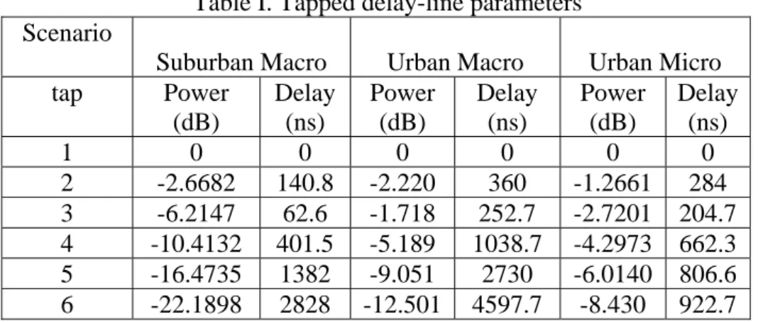
In order to compare the performance of the proposed timing synchronization for LTE cell search, we adopt the tapped delay-line model of SCM channel model described in [6]. There are three scenarios, the suburban macro, urban macro and urban micro. The channel tap delay-line parameters are shown in Table I. We consider one antenna transmitter and receiver. The 15MHz LTE system was considered, with sampling rate of 23.04 MHz, 1024-point DFT/IDFT size, normal CP and 15 kHz subcarrier spacing. We also considered the mismatch of oscillator up to 10 ppm, with corresponds to ε =1.33.
Table I. Tapped delay-line parameters Scenario
Suburban Macro Urban Macro Urban Micro
tap Power (dB) Delay (ns) Power (dB) Delay (ns) Power (dB) Delay (ns) 1 0 0 0 0 0 0 2 -2.6682 140.8 -2.220 360 -1.2661 284 3 -6.2147 62.6 -1.718 252.7 -2.7201 204.7 4 -10.4132 401.5 -5.189 1038.7 -4.2973 662.3 5 -16.4735 1382 -9.051 2730 -6.0140 806.6 6 -22.1898 2828 -12.501 4597.7 -8.430 922.7
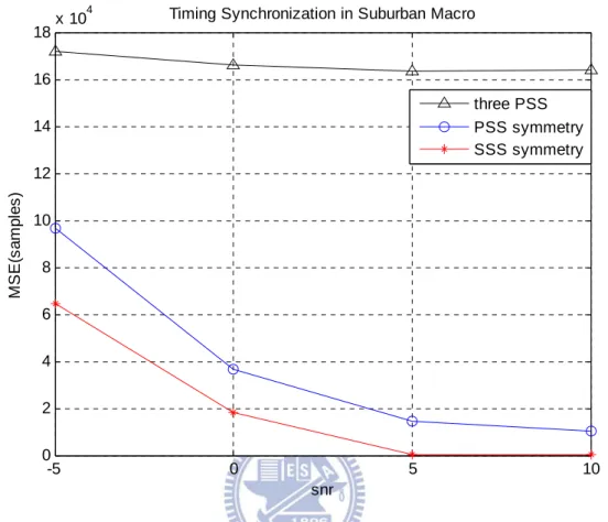
Fig. 3.1 shows the root mean square error (MSE) of the OFDM timing estimation measured in samples; the MSE is plotted against the SNR with channel scenario of suburban macro. When CFO is large, Method one performs poorly and the timing synchronization is quite off. MSEs of Method two and Method three decrease when SNR increases. Method
Three performs better even under the other two channel scenarios. Nevertheless we still have to confirm PSS detection and NIDcell detection performance.
-5 0 5 10 0 2 4 6 8 10 12 14 16 18x 10 4 snr M S E (sa m p le s)
Timing Synchronization in Suburban Macro
three PSS PSS symmetry SSS symmetry
Fig. 3.1 Timing synchronization in terms of the MSE measured in samples against the SNR.
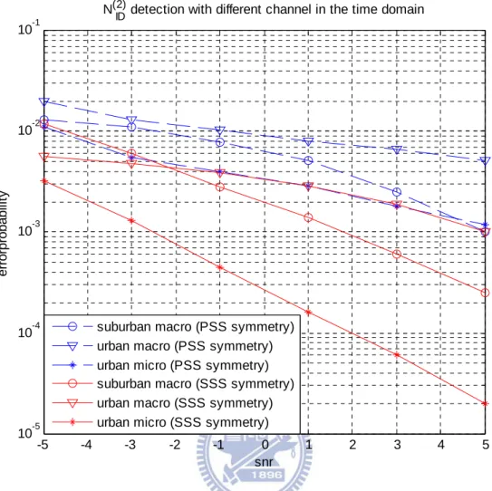
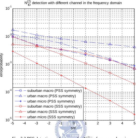
Fig. 3.2 shows the PSS detection for NID(2)in time domain and Fig. 3.3 in frequency
domain. We can see the performance is related with the channel scenarios. The error probabilities are similar whether by time or frequency-domain methods. With CFO, method two, which is doing timing synchronization with PSS, cannot catch the correct symbol time. The worse timing synchronization also leads to worse CFO compensation. Method three, which is doing timing synchronization with SSS, is immune to CFO. Thus ISI and ICI are diminished. Consequently the performance of method three is better than method two.
-5 -4 -3 -2 -1 0 1 2 3 4 5 10-5 10-4 10-3 10-2 10-1 snr e rrorp rob a b ili ty
N(2) ID detection with different channel in the time domain
suburban macro (PSS symmetry) urban macro (PSS symmetry) urban micro (PSS symmetry) suburban macro (SSS symmetry) urban macro (SSS symmetry) urban micro (SSS symmetry)
-5 -4 -3 -2 -1 0 1 2 3 4 5 10-5 10-4 10-3 10-2 10-1 snr erro rpro ba bi lit y
N(2) ID detection with different channel in the frequency domain
suburban macro (PSS symmetry) urban macro (PSS symmetry) urban micro (PSS symmetry) suburban macro (SSS symmetry) urban macro (SSS symmetry) urban micro (SSS symmetry)
Fig. 3.3 PSS detection performance forNID(2)in frequency domain.
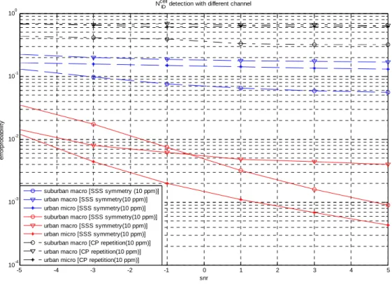
Fig. 3.4 shows the detection performance forNIDcell. The S-SCH sequences with different
) 1 (
ID
N has variation just cyclic shift. If the sequence have some interference of other response, the detection result would be wrong. For this reason the SSS detection is very sensitive to ISI and ICI. The detection performance of method two is also worse than method three. Consequently, method three is shown to have the advantage of lower complexity than method one and better performance than method one and two. In this figure, we also compare the traditional method of using CP repetition to find symbol boundary. The performance is worst.
-5 -4 -3 -2 -1 0 1 2 3 4 5 10-4 10-3 10-2 10-1 100 snr e rr o rp ro b a b ilit y
Ncell ID detection with different channel
suburban macro [SSS symmetry (10 ppm)] urban macro [SSS symmetry(10 ppm)] urban micro [SSS symmetry(10 ppm)] suburban macro [SSS symmetry(10 ppm)] urban macro [SSS symmetry(10 ppm)] urban micro [SSS symmetry(10 ppm)] suburban macro [CP repetition(10 ppm)] urban macro [CP repetition(10 ppm)] urban micro [CP repetition(10 ppm)]
Fig. 3.4 Detection performance for NIDcell
3.2 Summary
A cell search procedure is proposed for 3GPP LTE downlink. The cell search procedure utilizes a new timing synchronization method to increase the reliability of cell search results. The timing synchronization algorithm can effectively combat the impairments caused by CFO with low computation complexity and help achieving better performance in Cell-ID detection. We verified the idea by link level simulation with 3GPP LTE channel models.
Bibliography
[1] 3GPP TS 36.211 V8.5.0,”Physical Channels and Modulation (Release 8)”, Dec.2008
[2] Farooq Khan, “LTE for 4G broadband”, Cambidge University Press 2009.
[3] M.Sandell, JJ. v.d. Beek and P.O.Borjesson, “Timing and Frequency Synchronization in OFDM System Using Cyclic Prefix”, Proc. IEEE Int. Symp. Synchronization, Essen, Germany, Dec. 1995
[4] Pei-Yun Tsai Hsiang-Wei Chang,’’ A new cell search scheme in 3GPP long term evolution downlink, OFDMA systems’’, Wireless Communications & Signal Processing, 2009. WCSP 2009
[5] Jung-In Kim Jung-Su Han Hee-Jin Roh Hyung-Jin Choi Sch. of Inf. & Commun. Eng., Sungkyunkwan Univ., Suwon, South Korea ,” SSS detection method for initial cell search in 3GPP LTE FDD/TDD dual mode receiver”, Communications and Information Technology, 2009. ISCIT 2009. 9th International Symposium on.
[6] Baum, D.S. Hansen, J. Salo, J. ETH Zurich, Switzerland, ‚‘‘An interim channel model for beyond-3G systems: extending the 3GPP spatial channel model (SCM)’’, Vehicular Technology Conference, 2005. VTC 2005-Spring. 2005 IEEE 61st.
[7] 3GPP TS 36.300 V8.5.0, ”Evolved Universal Terrestrial Radio Access(E-UTRA) and Evolved Universal Terrestrial Radio Access Network(E-UTRAN)”, Dec.2008
(Release 8), Dec.2008
[8] Konstantinos Manolakis, David Manuel Guti´errez Est´evez, Volker Jungnickel, Wen Xu, Christian Drewes, ” A Closed Concept for Synchronization and Cell Search in 3GPP LTE Systems”, Wireless Communications and Networking Conference, 2009. WCNC 2009. IEEE, 5-8 April 2009
[9] Popovic, Branislav M, Fredrik, “Primary Synchronization Signal in E-UTRA”, Spread
Spectrum Techniques and Applications, 2008. ISSSTA ’08. IEEE 10th International
Symposium on
[10] S. H. Chen, W. H. He, H. S. Chen, and Y. Lee, “Mode detection, synchronization and channel estimation for DVB-T OFDM receiver” IEEE Global Communication Conference, vol. 5, Nov. 2003, pp. 2416-2420