行政院國家科學委員會專題研究計畫 成果報告
L 閥之壓力擾動與穩定性探討
計畫類別: 個別型計畫
計畫編號: NSC93-2214-E-002-024-
執行期間: 93 年 08 月 01 日至 94 年 10 月 31 日
執行單位: 國立臺灣大學化學工程學系暨研究所
計畫主持人: 呂理平
報告類型: 精簡報告
報告附件: 出席國際會議研究心得報告及發表論文
處理方式: 本計畫可公開查詢
中 華 民 國 95 年 1 月 18 日
L 閥之壓力擾動與穩定性探討
Analysis of Pressure Fluctuation Signals of an L-valve
張以侖 (Y. L. Chang)、呂理平 (L. P. Leu)*
國 立 台 灣 大 學 化 學 工 程 學 研 究 所 國科會編號:NSC93-2214-E002-024 計畫主持人在工程科技推展中心帳號: 0100949
摘要
本實驗裝置採用內徑為 80mm 的壓克力管所製成之下降管和 L-閥。實驗中以量測 L-閥中的固體流量及壓力擾動 訊號,探討不同上升床流速、通氣位置、通氣方向和通氣深度對 L-閥的固體流量、壓力差和壓力擾動標準偏差所造成 之影響。 結果顯示,固體流量隨通氣位置的降低而增加。當 通氣量增加,使下降管中產生大型氣泡時,壓力擾動之標準偏差有急劇增加的現象。由不同通氣方向來看,通氣方向 向下時的固體流量雖略小於水平方向通氣,但可使下降管中的壓力擾動明顯減少,即可得到較穩定的操作。以不同的 通氣方向,在本實驗之最低通氣位置操作 L-valve 時,比較實驗結果可發現,當下降管底部和 L- valve 水平段所量測 到之壓力值幾乎不再增加時,可推測下降管所能產生的壓力差已達到最大值,即已達到其操作上限值。 關鍵詞: L-閥,壓力擾動標準偏差,固體流量。Abstract
The experimental apparatus consist of the downcomer and L-valve made by the transparent Plexiglas
column, 80mm i.d. The influence of the riser velocity, position of aeration tap, aeration direction and
aeration depth was determined by the measurement of solid flow rate, pressure drop and pressure
fluctuations at various pressure probe position.
The results show that the solid flow rate of L-valve increased with lower position of aeration taps.
The standard deviation of pressure signals increased sharply with the formation of large gas bubbles in the
downcomer. The solid flow rate of downflow of inlet gas was slightly less than that of horizontal flow of
inlet gas. But the standard deviation of pressure signals of downflow of inlet gas decreased significantly,
causing more stable operation. From comparing the results of different aeration directions by aerating at
the lowest position of aeration tap, when the pressure measured in lower part of the downcomer and the
horizontal section of L-valve was no more increased, that could suppose that the pressure drop of the
downcomer was its maximum value.
Keyword: L-valve, pressure fluctuations, solid flow rate
一、緒論
L-閥為固體流量控制裝置,其廣泛用於工業程序來 輸送固體,在氣相輸送、氣泡流體化床和循環式流體化 床中,為必要且重要的元件。L-閥本身不含可動元件且 操作時沒有機械性的運動,僅需外加通氣及管件本身即 可控制固體流量,因此常使用在嚴苛的環境下,如腐蝕 性氣體、粗糙粒子、高溫高壓等等。固體粒子通過 L-閥的方式,是以外部通入的氣體通過固體粒子所構成之 粒子床時,對固體粒子表面產生拖曳力。增加通入的氣 體量時,拖曳力也隨之增加,直到克服粒子間的摩擦力 後,固體粒子開始隨著氣體一起移動,而使流動通過 L-閥 (Arena et al., 1998 ; Knowlton, 1986 ; Yang and Knowlton, 1993)。本實驗將以各種變數,例如通氣位置、 通氣方向、上升床流速等,來探討不同變數對 L-閥之 固體流量、局部位置的壓力及壓力擾動所造成之影響,以 期更清楚了解 L-閥在操作時的變化。二、實驗裝置與步驟
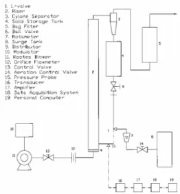
本實驗採用內徑為 80mm 的壓克力管所製成之 L-閥,實 驗設備如 Fig. 1 所示。固體粒子為平均粒徑 193 µm,密 度 2635 kg/m3 的砂。量測壓力訊號的探針分別位於在下降 管 (此處為 P16)、L-閥肘部 (此處為 P07) 和 L-閥水平段 (此處為P02)。
實驗過程中量測改變不同通氣量時 L-閥的 固體流量、壓力值和壓力擾動標準偏差值。再改變各種變 數如上升床流速、通氣位置與通氣方向 (如通氣方向向 下、水平和向上) 與通氣深度後,紀錄各種變數對 L-閥的 固體標量、壓差與壓力擾動標準偏差值所造成的影響。在此定義以內徑為 6mm 之通氣管,在下降管壁以水平方 向 的 方 式 通 氣 , 為 本 實 驗 之 標 準 操 作 (standard operation)。標準操作所得之結果作為其他變數的所得結 果之比較基準。
三、結果與討論
1. 不同通氣位置下,固體流量與通氣量的關係
將固體流量對通氣量作圖,如 Fig. 2 所示,在 B 點處幾乎沒有固體流量。由流態觀察,下降管中的固體 粒子看不出有任何明顯移動的現象。在 C 點處固體已 有明顯流動,故可知當通氣量位於 BC 區間時,固體有 開始流動的現象,即最小所需通氣量在 BC 區間內。若 將固體粒子之最小流體化速度和下降管截面積兩者之 乘積來區分通氣量的倍率,當通氣量為乘積的三倍 (2.1867 m3/h) 時,下降管中產生大型氣泡,甚至有駐塞 (slugging) 現象產生。此氣泡的產生會阻礙固體流動, 因此固體流量有下降的現象。在本實驗裝置中,通氣位 置 A1 離 L-閥肘部最近,A3 離 L-閥肘部最遠。若在 相同條件下操作 L-閥時,輸送固體的能力是:A1 > A2 > A3。此結果和 Knowlton and Hirsan (1978) 所提出當 通氣位置越低,固體流量越高的結論相同。2. 不同通氣位置下壓力擾動標準偏差與通氣
量的關係
將下降管所量測的壓力擾動標準偏差對通氣量作 圖,如 Fig. 3 所示,當通氣量到達前述乘積的三倍 (2.1867 m3/h) 時,在下降管中所量測的壓力擾動標準偏 差有急劇增加的現象。由流態觀察可知,在高通氣量 時,下降管中會產生大型氣泡,甚至是駐塞 (slugging) 的現象,故在下降管中所量測到的壓力擾動標準偏差有 急劇增加的趨勢。將 L-閥水平段所量測的壓力擾動標 準偏差對通氣量作圖,如 Fig. 4 所示,可發現在 L-閥 內的壓力擾動標準偏差隨著通氣量的增加而增加,其趨 勢似以指數上升,而並非如下降管中所量測到的壓力擾 動標準偏差有急劇增加的現象。由流態可看出,在 L-閥內並不會產生大型氣泡,而是產生砂丘狀的流動,故 所量測到的趨勢和下降管不同。3. 不同通氣方向
不同的通氣方向是在下降管壁的通氣位置,將通入 的氣體以向上、水平及向下的方向通入 L-閥中。就固 體流量而言,以通氣方向向下的方式操作 L-閥時,其 固體輸出量並未如預期中快速且大量的增加,反而使固 體流量減少。如 Fig. 5 所示,可明顯看出當通氣方向向 下時,下降管中的壓力擾動標準偏差從 A 到 F 點都相 當低。G 點雖然也有增加的趨勢,但可發現到其增加的 量相當少。由此可知,通氣方向向下時,雖不如預期的 增加固體流量,但可使向下降管頂部前進的氣體量減少 相當多,下降管內的氣體能儘量向 L-閥水平段推進。 而由流態觀察得知,以通氣方向向下操作 L-閥時,下 降管中幾乎不會產生氣泡,因此可抑制下降管中駐塞 (slugging) 的產生。若以通氣方向向上的方式操作 L-閥時,因通入的氣體方向為強制向上,和固體粒子的流向 相反。當通入的氣體形成大型氣泡時,會阻礙固體的穩定 下降。在 L-閥水平段處量測壓力擾動標準偏差時,如 Fig. 6 所示,可看出當固體流量少時,隨著固體粒子通過 L-閥 水平段的氣體也會減少,因此在 L-閥水平段所量測到的壓 力擾動標準偏差也會減少。4. 不同通氣深度
不同通氣深度的操作方式是以在下降管壁和在下降 管中心通氣來作比較。以下降管中心通氣的方式操作 L-閥時,通氣管出口位置距離 L-閥肘部直角處較在下降管壁 通氣時來得接近,因此通入的氣體容易快速進入至 L-閥水 平段,壓力探針所量測到較高的氣體流量,但氣體卻無法 有效驅動固體粒子來增加固體流量。5. L-閥肘部、水平段壓力值與下降管中固體穩
定移動之關係
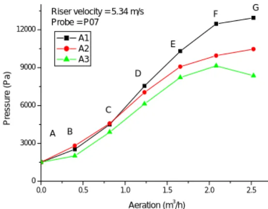
在下降管底部所量測到的壓力值對通氣量作圖,如 Fig. 7 所示,可發現在 FG 區間處的斜率小於其他各區間 的斜率,且接近持平的現象。在 L-閥水平段部份,如 Fig. 8 所示,亦可發現到當通氣量增加時,水平段的壓力亦達 到飽和狀態。由循環床壓力平衡來看,下降管所須平衡的 壓差逐漸到達下降管所能產生壓力的最大值後,氣體轉向 壓力較低的下降管頂部前進。下降管底部和 L-閥水平段壓 力值增加的趨勢減緩,甚至持平的現象。因此可經由量測 下降管底部和 L-閥水平段的壓力值變化來判定下降管中 的流態是否已由移動床轉變為流體化床,進而判定 L-閥之 操作上限。四、結論
1. 以通氣位置而言,通氣位置越接近 L-閥肘部時,產生的 固體流量越高,同時在 L-閥水平段所量測到的壓力擾動標 準偏差也較高。 2. 以不同通氣方向通氣時,發現採用通氣方向向下時,固 體流量雖略為減少,但可減少下降管中的壓力擾動,抑制 駐塞 (slugging) 的發生,即可得到較穩定的操作。 3. 當下降管底部和 L-閥水平段壓力值增加的趨勢開始減 緩,甚至持平的現象,可推測下降管中的壓差已達到最大 值。因此可經由量測下降管底部和 L-閥水平段的壓力值變 化來判定下降管是否已轉變流態,進而判定 L-閥之操作上 限。五、符號說明
A1、A2、A3 Position of aeration tap. (-)
六、參考文獻
Arena, U., C. B. Langeli and A. Cammarota, "L-valve Behaviour With Solid of Different Size and Density", Powder Technol., 98, 231-240 (1998).
Geldart, D., “Types of Gas Fluidization”, Powder Technol., 7, 285-292 (1973).
Geldart, D. and P. Jones, “The Behaviour of L-valves With Granular Powder”, Powder Technol., 67, 163-174 (1991). Knowlton, T. M. and I. Hirsan, "L-valves Characterized for Solids Flow", Hydrocarbon Proc., 57, 149-156 (1978). Knowlton, T. M., "Standpipes and Return Systems", in Circulating Fluidized Beds, J. Grace, A.A. Avidan and T.M. Knowlton (Eds.), Chap. 7, pp. 214-260, Blackie Academic and Professional, London (1997).
Knowlton, T. M., “Solid Transfer in Fluidized Systems”, in Gas Fluidization Technology, D. Geldart (Eds.), Chap. 12, pp. 341-414, Wiley, New York (1986).
Yang, W. C. and T. M. Knowlton, "L-valve Equations", Powder Technol., 77, 49-54 (1993).
黃文濬, "循環式流體化床之壓力擾動訊號分析", 化工 系碩士論文, 國立台灣大學, 台北, 台灣 (2003).
Fig. 1. Schematic diagram of experimental
system.
0.0 0.5 1.0 1.5 2.0 2.5 0 100 200 300 400 500 G F E D C B A Riser velocity = 5.34 m/s A1 A2 A3 Solid f low rate(k g/h ) Aeration (m3/h)Fig. 2. Solid flow rate vs. aeration flow
rate in standard operation.
0.0 0.5 1.0 1.5 2.0 2.5 0 100 200 300 400 500 600 G F E D C B A A1 A2 A3 Riser velocity = 5.34 m/s Probe = P16 Stand ar d De v iati o n ( P a) Aeration (m3 /h)
Fig. 3. Standard deviation of pressure signals vs.
aeration flow rate at downcomer in standard
operation.
0.0 0.5 1.0 1.5 2.0 2.5 0 200 400 600 G F E D C B A Riser velocity = 5.34 m/s Probe = P02 A1 A2 A3 S tan da rd D e v iat io n ( P a) Aeration (m3 /h)Fig. 4. Standard deviation of pressure signals vs.
aeration flow rate at downcomer in standard
operation.
0.0 0.5 1.0 1.5 2.0 2.5 0 100 200 300 400 500 600 G F E D C B A Riser velocity = 5.34 m/s Probe = P16 A1 A2 A3 Stan da rd D e v ia ti o n (Pa ) Aeration (m3 /h)Fig. 5. Standard deviation of pressure signals vs.
aeration flow rate at downcomer in
downflow of inlet gas.
0.0 0.5 1.0 1.5 2.0 2.5 0 100 200 300 400 500 600 G F E D C B A A1 A2 A3 Riser velocity = 5.34 m/s Probe = P02 Stand ar d De v iati o n ( P a) Aeration (m3 /h)