行政院國家科學委員會專題研究計畫 成果報告
捷運地下車站火災煙流分析與人流測試(2/2)
計畫類別: 個別型計畫 計畫編號: NSC92-2212-E-002-033- 執行期間: 92 年 08 月 01 日至 93 年 07 月 31 日 執行單位: 國立臺灣大學應用力學研究所 計畫主持人: 陳發林 報告類型: 完整報告 處理方式: 本計畫可公開查詢中 華 民 國 93 年 9 月 7 日
行政院國家科學委員會專題研究計劃成果報告
捷運地下車站火災煙流分佈與人流測試(2/2)
計劃編號:NSC 92-2122-E-002-033 執行時間:92/08/01 ~ 93/07/31 主持人: 陳發林教授 研究生:郭新章、張文嘉先生 執行單位:國立台灣大學 應用力學所 共同研究人員:簡賢文教授,沈子勝教授,趙勇維先生,鄭震崇先生 ABSTRACTSThis is a two-year project, in which two parts of research had been implemented and the results are reported in the following, in which the text are divided into two portions.
Part 1: SMOKE CONTROL IN FIRES OF TAIPEI TRTS SUBWAY STATION We investigate the effectiveness of the smoke control scheme of Gong-Guan Subway Station, a typical subway station of Taipei Rapid Transit System and whose mechanical control systems are also standard in modern subway station design. The three-dimensional smoke flow fields under various kinds of fires are computed by the computational-fluid-dynamic technique and results are illustrated on various cross sectional planes. Results indicate that, the stack effect plays a deterministic role on smoke control when fire occurs near the stairwell; under such a circumstance, no mechanical smoke control is necessary. When fire occurs in other places, such as at the end or the center of platform, the current mechanical control schemes of GGSS are effective; namely, the smoke can be well controlled, either is confined to a small region or is evacuated out of the station, leaving the four exits free of smoke so that
the passengers can escape through them. The effect of the platform edge door (PED) on the smoke control is also investigated. With PED, the effectiveness of the present smoke-control system for fires occurring on the chassis of train, a serious fire in the subway station, increases. We also propose an innovative smoke-control scheme with PED, which turns out to be much more efficient in evacuating the smoke than used currently. Present study provides both valuable information to the design of the passenger evacuation routes in fires as well as criteria to the design of smoke control system of subway stations.
PART II: THE EVALUATION RESEARCH OF EVACUATION SAFETY IN TAIPEI TRTS UNDERGROUND STATION
This part of research utilized the buildingEXODUS for the simulation of evacuation in Hsing-Dein subway station (HDSS), a typical underground MRT station of Taipei Rapid Transit System (TRTS). Through this model, the inappropriate or unreasonable evacuation routes for occupants were illustrated, and Exit Potential and Exit Attractiveness for occupants could also be adjusted. Through the optional panel, the user has complete control over the distribution used to represent the Occupant attributes, which have great influence in evacuation process. Simultaneously, the packed or staggered behavior on staircases could be revised and he/she could get better simulation results, which are closer to the real evacuation scenarios than those obtained from computation.
PART I : SMOKE CONTROL IN FIRES OF TAIPEI TRTS SUBWAY STATION
1. INTRODUCTION
Fires in subway stations happened frequently in history, especially in the past two decades when subway has become a major transportation scheme in metropolitan area. The cases listed in Table 1 [1] are only a few examples having claimed life of passengers. Some of the cases are pure accidents, while many of them were caused by vandalism and terrorism attacks. Two well-known major accidents have made indelible imprints in our memories, both causing a large number of victims: One happened in London King’s Cross subway station and one in Baku (capital of Republic of Azerbaijian) subway tunnel. The fire in King’s Cross subway station happened in November 18, 1987, causing 87 people either die or serious injure. The fire in Baku happened in October 29, 1995, which had been even more serious, the hot air and toxic smoke killed 337 people and left 227 seriously injured. From the results obtained from the computational fluid dynamics (CFD) simulation of King’s Cross fire [2], it was found that the smoke movement in this complicated station could be hardly predicted and the smoke control is crucial in fire emergency; more precisely speaking, for example, the buoyant smoke may move rapidly through the stairwells, blocking the passages through which passengers are supposed to evacuate.
In fires of subway stations, the most immediate threat to passenger’s life is not the direct exposure to fire, but the smoke inhalation because it contains hot air and toxic gases. To understand the mechanisms driving the motion of smoke is therefore an important issue for fire safety and to confirm the effectiveness of the smoke control systems in subway stations is also a necessity before the station is opened for public service. We will do this confirmation for Gong-Guan subway station (GGSS, see Fig.
1) although she has been opened for service since 1998. To do this, we investigate the smoke propagation in GGSS under various kinds of fires. The GGSS is a typical mid-way subway station of Taipei Rapid Transit System (TRTS), which currently consists of 6 lines and 63 stations, totally 86.8km long, serving to commute more than 1 million passengers per day in Taipei metropolitan area. In the second phase of construction, there will be 7 new lines to add into TRTS, rendering it become one of the largest scale metropolitan transportation systems in the world. The GGSS, serving to commute more than 20,000 passengers per day, is equipped with three mechanical smoke control systems, which are standard equipments for modern subway stations. The analysis of smoke propagation of present study can accordingly account for a representative case for TRTS and other modern subway systems.
Accordingly, we investigate the effectiveness of the smoke control systems of GGSS: the tunnel ventilation fan (TVF), the under platform exhaust (UPE) system, and the smoke evacuate gate (SEG), see Fig. 1(a). The computational fluid dynamic (CFD) approach is employed to investigate the three-dimensional smoke flow field of GGSS. Special emphasis is placed on the evolution of the smoke propagation under smoke control, and an innovative smoke control scheme is also proposed. We note also that, in fires occurring in an enclosure such as the subway station, a natural convection phenomenon named “stack effect” may play a significant role in smoke propagation when no mechanical system is engaged. It is because in most enclosures there are various kinds of structural vertical spaces through which the buoyancy force of hot smoke is enhanced. The pressure difference induced by stack effect can be much larger than that due to other driving forces, such as expansion of combustion gas, wind effect, and so on [3]. As soon as the stack effect forms, the smoke generated in enclosure will move towards and into the vertical shafts, such as the stairwell, the shaft of elevator, or the vertical shaft of ventilation system, becoming an important
phenomenon to which the design of smoke control system has to seriously consider. Accordingly, the stack effect is also one of the major issues to be studied here.
In the following, we introduce the architectural configuration and the smoke control systems of GGSS in section 2. A detailed description of the mathematical model and relevant boundary conditions are given in section 3. In section 4, we show many typical examples of smoke propagation in GGSS. Three-dimensional computational results are illustrated by the temperature and velocity vector distributions on various cross sectional planes. In section 5, the stack effect on smoke propagation are discussed, emphasis is placed on the characteristics of this natural convection and results may cast a general rule with which the design of smoke control in subway stations can follow. Section 6 is the major part of the present paper, in which the effectiveness of the smoke control system of GGSS is discussed extensively. In section 7, the effect of “platform edge door” (PED) on smoke control is discussed, in which fire occurs on the chassis of train is considered and the superiority of PED on smoke control can be clearly seen. It turns out that, with PED, an innovative smoke control scheme of great performance can be made. Finally, in section 8 several concluding remarks are drawn.
2. SMOKE CONTROL SYSTEMS OF GGSS
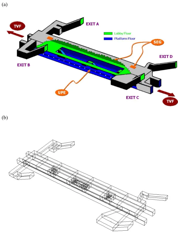
As a typical midway station of TRTS, the GGSS has two floors: the platform floor at bottom, in which an island-platform sits between the two rails of opposite bound (Fig. 2(a)), and the lobby floor at top, in which two hallways (Fig. 2(b)) at the two ends of the floor connect the lobby and four stairwells (or exits, Fig. 2(c)). The length of the station is 142.1m and the width is 17.9m. The height of the lobby floor is 4.15m and that of the platform floor is 5.15m. In view of the beauty of the interior of station and the relaxation of the mental pressure due to the space limitation of
platform floor, a large area at the center of lobby floor is cut off, remaining two two-meter-width passages on the edge (Fig. 2(a)). This cut-off of the lobby floor, unfortunately, enhances the buoyancy force of hot smoke, making the smoke control in GGSS more difficult.
To ensure the smoke be well controlled during fires, the station is equipped with three mechanical systems serving to evacuate smoke (Fig. 1(a)): (1) The TVF locates in the tunnel near the two ends of the platform floor, sucking the air into tunnels and evacuating to the road surface, inducing an approximately 5m/s wind into tunnels. (2) The UPE locates below the platform, having totally 36 openings along the two sides of the platform (18 on each side), inducing an approximately 2m/s flow into the opening. (3) The SEG locates on the ceiling of lobby floor, having totally 8 gates uniformly distributed along the ceiling, inducing an approximately 2m/s flow into the gate; see please the two SEG (in square shape) shown in Fig. 2(d). As fire occurs, the person-in-charge in the control center will observe both the location and the development of fires and then decides which system shall be engaged to evacuate smoke [4]. There is another smoke control setup named smoke blocking wall (SBW) being a necessity to accommodate to fire-safety regulation in Taiwan. There are seven SBW dividing the ceiling into eight zones. The SBW hangs down from the ceiling and is approximately 1.3 meter high. These walls are designed to confine the smoke within the smoke zone and this scheme is named as the smoke-zone compartment, with which the smoke propagation in large open space will be damped significantly. The SBW is also considered in the present computations.
The four exits in GGSS direct respectively to the campus of National Taiwan University (Exits B and C) and to Shuei-Yuan traditional market (Exit D) and Da-Xue-Kou, a complex restaurant district (Exit A). All these places are busy-life area, so that GGSS serves to commute more than 20,000 passengers per day. Each exit is
accompanied with one or two escalators, connecting the lobby floor and the surface road, forming a space (or stairwell) through which the stack effect may predominate the smoke movement in station fires when no mechanical smoke control is engaged. As smoke moves into stairwells, the evacuation of people from subway station through these exits is prohibited, influencing dramatically the whole evacuation plan in fire emergency.
3. MATHEMATICAL MODELS AND NUMERICAL SCHEME
To investigate smoke propagation in GGSS, we employ CFD approach to compute the three-dimensional flow of the subway station. A reliable CFD result regarding the smoke movement in fires can be obtained when the following points are carefully treated [5]: (1) The flow in the subway station, especially that near the fire, shall be three-dimensional. (2) A careful choice of both the turbulent model and the corresponding input parameters is crucial. (3) The fire can be taken as a source of heat and smoke (accounted for by CO [6]) in which no combustion is considered. To 2
meet these requirements, a computer code named CFX4 developed by AEA Co. of England is employed to solve the flow field. In this code the finite volume numerical scheme is employed.
We note that the turbulent model employed in CFX4 code is the standard k−ε
model, which serves well to simulate the mean flow field. The detailed turbulent structure of the flow can be obtained when proper modification of the model has been made, and some specific modifications are necessary for some flows of special structure, for example, the flow near the sharp corner and the flow near the fire with strong chemical reaction. A large volume of research on the turbulence modeling of flame had been reviewed by Libby and Williams [7]. The effect of turbulence modeling on the computational results of buoyant diffusion flames had also been
discussed by Liu and Wen [8]. In present paper, we have no intention to emphasize the detailed structure of the turbulent flow. But, instead, the emphasis is placed on the investigation of the efficiency of the smoke evacuation schemes of GGSS. As a result, the mean flow shall be the major part to be examined while the detailed turbulent structure having minor effect on the smoke movement can therefore be neglected. Accordingly, the standard k−ε turbulence model considered in the CFX4 code shall to some extent meet the purpose of present paper.
The mathematical model and relevant boundary conditions are shown in the following, the details of the numerical approach are referred to the manual of CFX4. The governing equations are [9]
the continuity equation
+∇•( )=0 ∂ ∂ U t ρ ρ , (1)
the momentum equations
ρ +∇• ρ = +∇•σ ∂ ∂ B U U U t( ) ( ) , (2)
the energy equation
B U U Q t P T H U H t ∂ + • +∇• • + ∂ + ∇ • ∇ = • ∇ + ∂ ∂ ) ( ) ( ) ( ) (ρ ρ λ τ , (3)
and the mass generation equation
YC UYC YC SC t +∇• =∇• ∇ + ∂ ∂ ) ( ) ( ) (ρ ρ κ . (4) In above equations, ρ accounts for the density, U the velocity vector ( vu, ), B
the body force, PI U UT e U I
e(∇ +∇ )−(2/3) (∇• )
+ −
= µ µ
σ the stress tensor, H
the total enthalpy, λ the heat conductivity, T the temperature, P the pressure,
U U
U T e
e ∇ +∇ − ∇•
=µ µ
τ ( ) (2/3) , Q the heat source, Y the mass fraction of C
2
model yields µe =µt +µ and µ ρCk2 /ε
t = , where µ is the dynamic viscosity,
09 . 0 =
C [6], k is the local kinetic energy of fluctuation motion, and ε is the energy dissipation rate. The values of these parameters used are the same as those of [5], they are respectively σk =1, 217σε =1. , 1σh = , C1 =1.44, C2 =1.92 ,
0 3 =
C and Cµ =0.09. The notations of these parameters are the same with those used in ref [5], to which the reader is referred for their physical meanings.
To solve above equations, we employ CFX4 code. The computational domain is the three-dimensional GGSS (Fig. 1). Note that, since in the present paper we do not consider combustion so that the fire is considered as the source of heat and smoke. Nevertheless, for the convenience in the following discussions, “fire” will be used to account for the heat-smoke source. As found from the product analysis of combustion, the fire having a heat release rate 5MW is accompanied with a smoke generation rate
s ppm /
10 4 .
1 × 5 [10], both are fixed in present paper except in section 7 where a fire of 10MW and 2.8×10⁵ppm /s simulating the fire on the chassis of train is
considered. The computational field of GGSS is imbedded with a multi-grid system, in which the space is divided into 125 blocks (Fig. 1(b)). In each block the grid is uniformly distributed, but the grid size of the block can be different to each other, depending on the characteristics of flow. For example, the grid in the block containing or near the fire shall be finer than those away from the fire; the grid near the corner where the flow changes rapidly shall also be finer than those without geometry change. It turns out that the number of grid for GGSS is more than 300 thousand.
To compute the smoke flow in GGSS, the following boundary conditions are prescribed. On the boundaries of the four exists and the four tunnel entrances, constant pressure is prescribed because no approaching train or no pulsating air movement caused by train movement is considered. On the same boundaries, the
continuities of heat and mass fluxes are also prescribed. On the solid walls, non-slip condition and constant temperature and zero-smoke-flux are assumed. When stack effect is investigated, since it is a natural convection phenomenon and no mechanical smoke control system is engaged, all above boundary conditions are valid. When mechanical smoke control system is engaged, the following boundary conditions shall be considered: When UPE is active, a flow of 2m/s into the UPE opening is prescribed. When SEG is active, a flow of 2m/s into the gate is prescribed. When TVF is active, a flow of 5m/s into the four tunnels is prescribed. No radiation is considered in the present model, which under some circumstances may nevertheless have significant effect on the smoke movement when the scale of fire is large, which may merit further investigation in the future. To each computation, the numerical stability and numerical accuracy are checked by a test of changing the number of iteration. Normally, a 20-time-iteration or higher is needed to get a converged solution. For a fire of 5MW, it takes about 6 hours to run through a case in a PC with a Pentium4-1.8GHz-CPU and 128MB RAM.
4. SMOKE PROPAGAION IN GGSS
To illustrate the smoke propagation in GGSS, we begin with the flow in GGSS induced by a fire of 5MW occurring on the left of lobby floor (Fig. 3), where no mechanical smoke control system is engaged. In this three-dimensional picture, there are five vertical cross sectional (VCS) planes. In each plane the temperature distribution represented by colors (Fig. 3(a)) and the flow by velocity vectors (Fig. 3(b)) are shown. Both the temperature level and the velocity amplitude are accounted for by the color bars above each sub-figure, where the temperature ranges from 300oK (dark blue) or below to 400oK (orange) or above and the velocity ranges from
same color level is employed.
Both figures show the results at t = 4min that part of the smoke has moved into the center of lobby floor as well as down to the platform floor, while most of the smoke has moved into the two stairwells to evacuate out of the station. It is interesting to note from Fig. 3(b) the velocity vectors on the middle VCS plane that part of the flow is moving to the left, which is due to the stack effect occurring in the two stairwells on the left. In other words, the hot smoke reaches to the two stairwells at left first, which in turn induces a strong buoyancy flow in the stairwells, making the stairwells become low pressure zones and suck the air out of the station. Similar phenomena are also found in other cases under different fire conditions. Details of stack effect will be discussed in next section.
Note that, as shown in Fig. 3 and other figures of present paper, we will employ mostly the temperature distributions and sometimes the velocity vectors on different cross sectional planes and at different time steps to illustrate the evolution of smoke propagation in the station. In qualitative sense, the temperature distributions are quite similar to the smoke distribution accounted for by the concentration distribution of CO 2 , which is primarily because the diffusivities of heat and CO 2 are of insignificant difference under the present parametric range considered, so that the propagation of CO2 can to some extent account for that of smoke [5]. Accordingly, the temperature distribution can also be interpreted as the smoke distribution, or the hot air movement is essentially equivalent to smoke movement.
Figure 4 illustrates a series of pictures regarding the temperature distributions on the middle VCS plane under fires at different locations. The results are categorized into three groups: Group A corresponds to the fire locating on the right of the lobby floor, Group B to the fire locating on the center of the lobby floor, and Group C to the fire locating on the right of the platform floor. In each group we present 6 pictures at
different times. In Group D, we show the temperature distribution on the horizontal cross sectional (HCS) plane locating one meter below the ceiling at t = 5min.
In Group A, the fire occurs on the right of the lobby floor, a small portion of smoke propagates to the left at t = 2min, while eventually moves back to the right and evacuates out of the station through the two stairwells due to stack effect. In Group B, the smoke propagates rapidly and moves into every corner of station in a short time, rendering a serious situation threatening the safety of passengers. In Group C, the fire locates on the right of the platform floor, the smoke moves into the center of station within a few minutes. Although the smoke eventually moves back to the right of station to evacuate because of again the stack effect, the smoke has stayed in a large part of station for more than 10min. This has led to a situation that one may not evacuate all the passengers in station within the 6min critical-limit suggested by NFPA [11], which is followed by most subway-system regulations including TRTS. In Group D, we compare the above three cases by observing the smoke distribution on the HCS plane one meter below the ceiling at t = 5min. It confirms that as the fire locates on the center of station, the smoke distribution is most serious and an efficient smoke control scheme is required. As fire occurs on the right of lobby floor, the stack effect plays a significant role to evacuate the smoke without the aid of mechanical ventilation system. As fire occurs on the right of platform floor, the smoke distribution can be serious. For this case, nevertheless, the existing smoke control system TVF can efficiently evacuate the smoke through tunnels, as shall be shown in section 6.
5. STACK EFFECTS IN GGSS
The stack effect is a complicated phenomenon in subway stations. The influencing factors can vary widely although, by and large, the area-factor and the location-factor are the two factors predominating in most situations [4]. To elucidate
this, we show two cases of different fire locations in the two groups of Fig. 5. In the first case (Group A) we impose a fire on the left of the lobby floor. At the beginning of fire (Fig. 5A(a)), most of the smoke moves equally to the two exits on the left of lobby floor while some of the smoke moves to the right (Fig. 5A(b)). But after the smoke starts to evacuate out of GGSS from the two exits on the left, the smoke moving to the right is sucked back to the left due to stack effect (Fig. 5A(c)). This is because the smoke motion is enhanced in the left exits, inducing a smaller pressure region on the left and thus a horizontal pressure gradient pointing to the left, sucking the smoke to move to the left afterwards. Above is the first stage of stack effect, showing the competition between the exits on the left and on the right of GGSS. Then the second stage of stack effect occurs; namely, the competition between the two exits on the left becomes significant. Eventually, the smoke chooses Exit B to evacuate because (1) Exit B is of smaller area and (2) in front of Exit A there is a space for the lift, which disturbs the movement of smoke. In brief, at the first stage of stack effect, the location-factor dominates the smoke movement, making the smoke move to the left of GGSS. Then at the second stage the area-factor takes over, leading to that most of the smoke are evacuated from Exit B. At this stage, as shown in Fig. 5A(d), Exit B is not wide enough to evacuate all the smoke so that a small part of smoke is propagating into the station.
In Fig. 5B we present the case of fire locating at the center of the platform floor. The smoke moves upwards rapidly, impinges on the ceiling, and propagates rapidly to the two ends of station (Fig. 5B(a)). The smoke reaches to the two ends in almost the same time (Fig. 5B(b)), while due to the smaller-area of Exit D on the right, the area factor of stack effect predominates the movement of smoke, inducing the smoke to move to the right (Fig. 5B(c)). And then the two stairwells on the right compete to evacuate the smoke, and obviously Exit D predominates over Exit C because of its
smaller area. Nevertheless, because the quantity of smoke is so large that Exit D is not sufficiently large to evacuate all the smoke moving to the right, Exit C also helps evacuate some of the smoke due to its large cross sectional area (Fig. 5B(d)). This case illustrates that competition occurs in two different stages: the first competition occurs between the exits on the left and the right, and the second competition occurs between the two exits on the right. While for both stages the area-factor is the sole factor influencing the smoke movement.
Note that the stack effect in subway stations can become complicated due to the fact that the configuration of the inner space of the subway station, such as the King’s Cross station of London subway system has three floors, can be very complicated so that other factors such as geometry-factor may play a role. Nevertheless, there is a rule-of-thumb of stack effect can be always followed with: The smoke will evacuate from the exit to which the smoke reaches first, and then all or most of the smoke in the station will move towards this exit to evacuate. In other words, the location factor plays a more significant role than the area factor. On the other hand, if there is no location factor, the area-factor will predominate the system; i.e. the smoke will evacuate from the exit of smaller area. However, if these two factors show up simultaneously, the location factor in general is more influential than the area factor.
6. EXAMINATION OF SMOKE CONTROL OF GGSS
In GGSS there are three mechanical schemes serve to evacuate smoke (see Fig. 1): TVF, UPE and SEG. In this section, we examine the performance of these smoke-control schemes. The case examined is the fire locating at the center of platform floor because it is the most difficult case as far as smoke control is concerned. The results are again categorized into three group: Group A shows the smoke propagation without smoke control (Fig. 6A); Group B shows the results with
active SEG (Fig. 6B); Group C shows the results with active TVF and UPE, which used to turn on simultaneously (Fig. 6C); Group D shows two horizontal planes of the case of Fig. 6C(b) regarding the smoke distributions in both the lobby and the platform floors (Fig. 6D).
Without smoke control (Fig. 6A), the smoke generated from the fire at the center of platform propagates rapidly in the station, rendering a dangerous environment to passengers. With active SEG (Fig. 6B), the smoke distribution is slightly improved, most of the smoke is confined to the central region of station while is still to some extent threatening the passengers because the smoke are quite close to the four exits. This is because the smoke generation rate of fire is larger than the evacuation rate through SEG. With active TVF and UPE (Fig. 6C), the smoke is well confined to a small region in the center of station, leaving the four stairwells free of smoke. This is because most of the smoke are evacuated through TVF and UPE, which can be seen more clearly from Fig. 6D. One can see from Fig. 6D(a) the smoke distribution on the HCS plane one meter below the ceiling that the SBW serve nicely to limit the smoke within the two smoke zones at the center. It is also seen from Fig. 6D(b) the smoke distribution on the HCS plane four meters above the platform floor that most of the smoke is evacuated through the tunnel below Exit D.
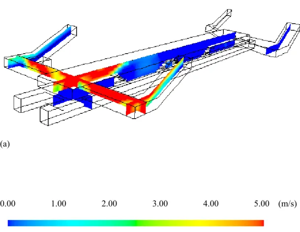
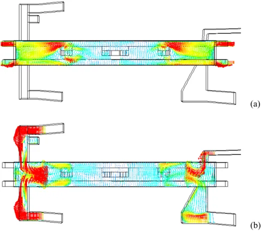
To illustrate more clearly the power of TVF and UPE, we show the detail flow structure of Fig. 6C(d) where the smoke is well controlled under the action of TVF and UPE. Figure 7(a) shows the velocity vectors in a HCS plane four meters above the platform floor. It is seen that strong winds (orange vectors) are induced near the two stairs and the four tunnels, which is obviously due to the strong suction from TVF and UPE inducing the fresh air to come down from the lobby floor through the cut-off area of lobby floor. Figure 7(b) shows the velocity vectors in a HCS plane one meter below the ceiling, confirming that the fresh air is sucked into the station through the
four stairwells. Note that the induced flow in Exit C is smaller than the others because of its larger cross sectional area. Figures 7(c) and 7(d) show the VCS planes on respectively the left ant the right of station, indicating again the strong winds induced by the suction of TVF and UPE pass through the stairwells rapidly.
Above results indicate invariably that the TVF and UPE of GGSS can control the smoke generated by the fire occurring in the center of station, and SEG is an auxiliary equipment helping evacuate the smoke attached to the ceiling. Regarding the case of fire occurring on the two ends of the lobby floor, the natural convection due to stack effect can serve well to evacuate the smoke through the nearby stairwells. For the case of fire occurring on the two ends of platform floor, the TVF can drive all the smoke to move into the tunnels near the fire, leaving both the platform and lobby floors free of smoke [1]. Present results also suggest that the existing smoke control schemes can meet the 6min critical-limit of NFPA since the smoke can always be well controlled from the beginning of fire not to move into the four exits. So that the passes for passengers to evacuate out of the station are all free of smoke, and they can move smoothly and leave the station without the disturbance due to smoke.
7. EFFECTS OF PLATFORM-EDGE DOOR
The platform edge door (PED) is a vertical wall made of transparent material such as reinforced plexiglass or others, partly or completely separate the spaces of platform and rails. On this transparent wall there are as many doors as the train, both sets of doors are aligned exactly in the same position and controlled automatically in the same phase; namely, they shall be opened or closed simultaneously. The concept of PED has been widely accepted in modern subway systems, and also has been set up in many new metropolitan subway systems, such as those in Hong Kong, Singapore, London Jubilee line (Fig. 8(a)), and so on. The motivation of setting up PED is
primarily due to the passenger safety requirement and partly due to the air condition energy saving. In fact, the later factor has been becoming more important to the countries in tropical or subtropical region, such as those in South-East Asia where the air condition system is definitely required. For GGSS, for example, although currently there is no PED setup (Fig. 8(b)), while the authority is considering build a full-height PED. With PED, according to the preliminary design data, the GGSS can save more than 35% of air condition energy consuming than without PED [1]. There is another benefit of PED that it will purge the flow in station caused by the piston effect of the train approaching the station [12], which used to induce an approximately 6m/s wind (usually containing oil-smell air) into the station, making passengers feel uncomfortable. In present section, we investigate from safety point of view the effect of PED on the smoke control if fire occurs in GGSS. The PED considered is a full-height style and has 14 doors on each side of platform, as many as the train consisting of seven wagons has. Each door is approximately 4.5-meter width, being as wide as those of train.
7-1. Comparison between cases with and without PED
Figure 9 show the smoke distributions on different cross sectional planes of the cases with and without PED when the fire occurring on a position 4 meters left from the center of the platform floor. In both cases, all the smoke control schemes TVF, UPE and SEG are active. For the case with PED, all the 28 doors are opened so that the smoke can move into tunnels through these doors. Figures 9(a) and 9(d) show the smoke distributions on the middle VCS plane without and with PED, respectively. Both cases show that the smoke is largely confined to the central part of station, and most of the smoke is evacuated from the two tunnels on the right of station. Figures 9(b) and 9(e) show respectively the smoke distributions without and with PED on the HCS plane one meter below the ceiling that, due to the effect of SBW, the smoke is
mostly blocked within the central part of station. Figures 9(c) and 9(f) show again for the two cases the smoke distributions on the HCS plane four meters above the platform floor. In Fig. 9(f) one can see the detailed flow structure of the smoke passing through the doors of PED into the rail space, reflecting that the computational grid is fine enough to reflect the important features of the flow.
Results of Fig. 9 imply that the appearance of PED does not influence the smoke control significantly when fire occurs on the platform. But a slight difference can also be seen: the smoke temperature is lower in the case with PED. This is because with PED the suction force from TVF is enhanced since the suction is concentrated on the 28 PED doors, rather than without any concentration as the case without PED. With this outcome, we propose a very efficient smoke control scheme with PED in the following.
7-2. An effective scheme utilizing PED to control smoke
With PED, as shown in Fig. 9(f), the suction force due to TVF is reflected by that the smoke in station will pass through the doors of PED and move into tunnels to evacuate. Since there are totally 28 doors along platform, the suction force is therefore divided into as many parts as the door number and distributed along platform, so that there is still a significant part of smoke left in the station. If there are only a few doors opened during fire, the suction force can therefore be more concentrated and stronger, and the smoke evacuation can be done more efficiently. Based on this idea, we proposed the scheme that, only a few doors near the fire are opened when fire occurs on the platform. A typical result is shown in Fig. 10, in which a fire occurs on the platform, locating 4 meters left to the center, and only the 8 doors of PED near the fire are opened, and all three smoke control systems are turned on. Results show that, by comparing Figs. 10(a), 10(b) and 10(c) (selected doors opened) with respectively Figs. 9(d), 9(e) and 9(f) (all doors opened), the smoke is sucked out of platform floor in a
much more efficient way, leaving only a much smaller part of smoke in the station. One can also see from the velocity vectors of Fig. 10(d) that strong winds are induced to pass through the eight doors opened, sucking the smoke into tunnels efficiently.
7-3 Smoke control when train got fire
The most dangerous case of fire is that the train is on fire and moves into the station. Under such a circumstance, the train shall stop in the station, opening the doors of train as well as those of PED’s to evacuate the passengers in a possible shortest time. The smoke control becomes complicated since the smoke may move with passengers into the platform floor or even the lobby floor since all doors are opened. We examine this case and the results are shown in Fig. 10. In these computations, the train in the computational domain is seen as a combination of seven empty rectangular boxes. Each box accounts for a wagon, in which two doors are opened on the boundary of box facing platform. As a result, the box has two opened areas through which the smoke can pass.
To examine the performance of the smoke control schemes of GGSS under such circumstances, we consider that a 10MW fire [11] occurs on the chassis of the central wagon of the train, all the doors of train and PED are opened and TVF, UPE and SEG are all active. A side view of the smoke propagation along tunnel is shown in Fig. 11, where the VCS plane locates 0.25 meter from the tunnel wall, sitting between the wall and the train body. It is seen that the smoke is attached to the ceiling of tunnel, being sucked by the TVF locating at the two ends of station. Only a small part of smoke leaks to the lobby floor, as shown in Figs. 11(c) and 11(d). The top view of the smoke propagation along tunnel (Fig. 12) is shown on a HCS plane four meters above the platform (higher than the train while lower than the ceiling of tunnel), which shows again that smoke is largely restricted within the rail space while is rarely seen in the platform floor. We also show in Fig. 13 the smoke propagation in a VCS plane cutting
through the center of the wagon got fire as well as the center of station (end view). It is seen that, at t = 10sec, the train has been surrounded by the smoke; at t = 1min, a small part of smoke has moved into both the station and the train since all doors are opened. But, nevertheless, afterwards the smoke is rapidly sucked out of both station and train, moving into the tunnels by way of TVF.
Although the doors of PED are opened when the train got fire, the existence of PED is still helpful on smoke control because it will to some extent block the smoke of train from moving into station. To illustrate this scenario, we show in Fig. 14 the case without PED when the train is on fire, corresponding to the case of Fig. 13. By comparing Figs. 13 and 14, one can see immediately clearly that without PED the smoke moves rapidly into the station, making the smoke control much more difficult than the case with PED. Note also that the efficient scheme of smoke control, i.e. the selected-door-opened scheme, cannot be used in the case of train got fired because all the doors of train and PED must be opened to evacuate the passengers at beginning. Then all the doors must be left opened for a few minutes (for example, six minutes) to ensure all passengers have left the train.
8. CONCLUSIONS
We have employed the computational-fluid-dynamics technique to investigate the propagation of the smoke generated by various kinds of fires occurring in the GGSS of TRTS. A three-dimensional computational domain fitting the interior of GGSS is setup (see Fig. 1), in which three mechanical smoke-control schemes TVF, UPE and SEG are considered by way of prescribing relevant boundary conditions. The fire is considered as a source of heat and mass, and the standard κ −ε
turbulence model is employed to account for the vigorous buoyancy-driven flow, in which both heat and mass transfers have significant effect on the structure of the
turbulent flow moving in such a complicated geometry of GGSS.
We first investigate the effectiveness of the smoke control systems of GGSS when fires occur in different possible locations. Results suggest that: (1) As fire occurs at the two ends of the lobby floor, the stack effect will predominate the smoke propagation and the smoke will evacuate through the stairwell(s) near the fire; no mechanical smoke control is needed. (2) As fire occurs in the central area of the platform floor, the buoyant flow will move upwards rapidly, impinges on the ceiling and spreads into every corner of station. Under such a circumstance, all the three mechanical smoke control systems shall turn on, then most of the smoke will be sucked out of station through the TVF in tunnels and the UPE under platform and a small part of smoke will evacuate through SEG, leaving the four exits through which the passengers are supposed to evacuate out of station free of smoke. (3) As fires occurs at the two ends of the platform floor, the smoke will also move rapidly to both the lobby and the platform floors if no mechanical smoke control is engaged, but will be evacuated out of station efficiently when the TVF close to the fire is active. In brief, with present mechanical smoke control systems of GGSS, the smoke generated by a fire of 5MW can be well controlled, leaving the emergency passages free of smoke so that the passengers can evacuate out of station smoothly. Note that 5MW is supposed to be the largest-possible fire will ever occur in normal situation of the subway station. While a fire larger heat release rate, say 10MW, can also be possible when the train got fire [10]. This kind of fire can also be well controlled if suitable scheme of smoke control is applied, as shown in section 7-3 the case of train-on-fire.
We also consider the effect on smoke control due to the appearance of platform edge door (PED), which has been widely accepted and setup in modern subway systems, especially those in the countries in tropical and sub-tropical regions. We consider two kinds of fire for this case: the fire occurs on the platform and the fire
occurs on the chassis of train. Results show that as fire occurs at the center of the platform floor, according to standard operation procedure all the doors of PED shall be opened, the smoke can be sucked out of the platform floor by TVF in tunnels. For the same fire, we propose a new scheme of smoke control: open only a few doors of PED near the fire. Consequently, due to the fact that the suction force from TVF is concentrated on only a few opened doors, the smoke will be efficiently evacuated out of station under the action of TVF. As fire occurs on the chassis of train, usually a 10MW fire, the existence of PED (although all the doors are opened) helps to restrict the smoke within the rail space and tunnel, making the smoke control much easier than without PED.
In conclusion, under the current smoke control schemes employed in GGSS, all passengers can be safely evacuated out of the station within a reasonable time, usually less than 6 minutes to fit the NFPA regulation, when normal fire accident happens. A more efficient smoke control scheme is available when PED is setup in the station. If only the standard operation procedure can be implemented normally in fire accidents, the safety of passengers in GGSS can be surely guaranteed. Since GGSS is quite typical in the modern subway station design and her smoke control systems are also standard, we believe that present conclusions may to some extent be also valid to other subway station of similar configuration.
REFERENCES
[1] Chen, F. and Chien, S. W., Development of escape model for passengers and analysis of shortest allowable evacuation time in subway stations of TRTS, Project Report, SinoTech Engineering Consulting Company, Taipei, 2001.
[2] Simcox, S., Wilkes, N. S., and Jones, I. P., Fire at King’s Cross underground station on 18th November 1987: Numerical simulation of the buoyant flow and heat
transfer, AERE-G 4677, UK, 1988.
[3] Zukoski, E. E., A review of flows driven by natural convection in adiabatic shafts, Report number NIST-GCR-95-679, 1995.
[4] Chang, W. J., Smoke propagation and stack effect in fires in subway stations, Master thesis, National Taiwan University, Taipei, Taiwan, 2001.
[5] Chen, F., Smoke propagation in road tunnels, ASME Applied Mechanics Review, 53 (2000) 207-218.
[6] Malhotra, H. L., Goods vehicle fire test in a tunnel, Proc Of the 2nd Int Conf On Safety in Road and Rail Tunnels, Granada, Spain, paper no. 28, 237-244, 3-6 April, 1995.
[7] Libby, P. A. and Williams, F. A., Fundamental aspects and a review, in Turbulent
Reacting Flows, Libby and Williams (eds), Academic Press, London, 1994.
[8] Liu, F. and Wen J. X., The effect of turbulence modeling on the CFD simulation of buoyant diffusion flames, Fire Safety Journal, 37 (2002) 125-150.
[9] Markatos, N. C., Malin, M. R. and Cox, G., Mathematical modeling of buoyancy-induced smoke flow in enclosures, Int. J Heat Mass Transfer, 25 (1982) 63-75.
[10] Ingason, H., Heat release rate measurements in tunnel fires, Proc of the Int. Conf. On Fires in Tunnels, Boras, Sweden, 86-103, 10-11 Oct., 1994.
[11] Standard for Fixed Guide Way Transit System, National Fire Protection Association 130, 1997
[12] Mendonca, F., Computational fluid dynamics (CFD) analysis of a decelerating train entering an underground station, Proc. 1st Int. Conf. on Computer Application in Transportation Systems, 24-26 June 1996, Basel, Switzerland, 89-100, 1996.
Time
City
Content
1964 March
New York
(USA)
Train on fire and then the equipments,
3 persons injured.
1968 January
Tokyo
(Japan)
Break of train burned, 11 persons
injured.
1970 September
Tokyo
(Japan)
Restaurant on fire, smoke propagates
into subway.
1976 February
London
(UK)
Platform equipments on fire,
electricity off, nine trains stop in
tunnels, 25 persons injured.
1979 September
New York
(USA)
Transformers on fire, 178 persons
injured.
1979 January
San
Francisco
(USA)
Spark from train ignites fire, one
person died and 44 injured.
1983 August
Nagoya
(Japan)
Station transformers on fire, 700
persons escaped into tunnel and one
firefighter died.
1984 November
London
(UK)
Warehouse of platform on fire,
damaged the ceiling and tunnel wall,
18 persons injured.
1985 July
London
(UK)
Escalator on fire, one person died and
47 injured.
1985 December
London
(UK)
Escalator on fire, 200 persons were
evacuated.
1987 November
London
(UK)
Escalator on fire, smoke propagates in
station, 84 persons injured.
1994 May
Taipei
(Taiwan)
Transformers on fire, smoke propagates
into the two stories of station, 10
firefighters injured.
1995 October
Baku
(Azerbaiji
an)
Train on fire, 337 persons died and 227
injured.
2000 April
Washington
DC (UAS)
Electrical cable burned, 273 passengers
on train were evacuated safely.
Figure 1 A schematic drawing of the Gung-Guan Subway Station.
(a)
Figure 2
Photos of the interior of GGSS. (a) A view from the top of the stair connecting the lobby and the platform floors. It is seen that the cut-off area of the lobby floor renders the interior of station becoming a connected large open space. (b) A view from the hallway of the lobby floor close to Exits C and D. On the top of photo is the vertical smoke blocking wall (SBW) made of plexiglass. (c) A view looking into the entrance of Exit C, the largest exit of GGSS. (d) The ventilation gates (round shape, 9 in the picture) and the smoke exhaust gates (SEG, square shape, two in the picture) on the ceiling. (a) (c) (b) (c) (d) (e) (f) (b) (d)
Figure 3 The three-dimensional stereo view of the smoke distribution in GGSS due to a fire locating on the left of the lobby floor. Each sub-figure shows (a) the temperature distribution and (b) the velocity vectors on several VCS planes: one longitudinal VCS passes through the middle of station, one transverse VCS locates on the left hallway connecting the lobby and the stairwells and two sit on the center of the stairwells.
300.00 325.00 350.00 375.00 400.00
(a)
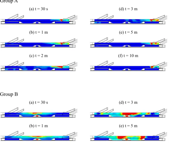
Figure 4 Smoke propagation due to fires at different locations. Groups A, B, and C show the smoke on the VCS plane cutting through the middle of station, and Group D show the smoke on the HCS plane locating one meter below the ceiling. In Group A, the fire occurs on the right of the lobby floor, the smoke is evacuated out of the station due to stack effect. In Group B, the fire occurs on the center of the lobby floor, the smoke propagates randomly in the station. In Group C, the fire occurs on the right of platform floor, the smoke moves to both the platform and the lobby floor, the stack effect is not so predominant as in Group A. In Group D, the sub-figures D(a), D(b) and D(c) correspond to A(e), B(e), and C(e), respectively. It is seen that the smoke propagation of Group B (fire at center) is the most serious case.
Group A (a) t = 30 s (d) t = 3 m (b) t = 1 m (e) t = 5 m (c) t = 2 m (f) t = 10 m Group B (a) t = 30 s (d) t = 3 m (b) t = 1 m (e) t = 5 m
(c) t = 2 m (f) t = 10 m Group C (a) t = 30 s (d) t = 3 m (b) t = 1 m (e) t = 5 m (c) t = 2 m (f) t = 10 m Group D (a) (b) (c) Figure 4 (end)
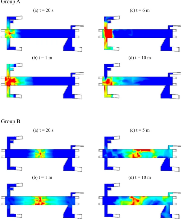
Figure 5 Stack effect on the smoke propagation in GGSS. In Group A, the fire occurs on the left of the lobby floor, Exits A and B compete to evacuate the smoke and eventually Exit B predominates. In Group B, the fire occurs on the center of the platform floor, the Exits A and B on the left and the Exits C and D on the right compete to evacuate smoke, and the Exits on the right predominate eventually.
Group A (a) t = 20 s (c) t = 6 m (b) t = 1 m (d) t = 10 m Group B (a) t = 20 s (c) t = 5 m (b) t = 1 m (d) t = 10 m
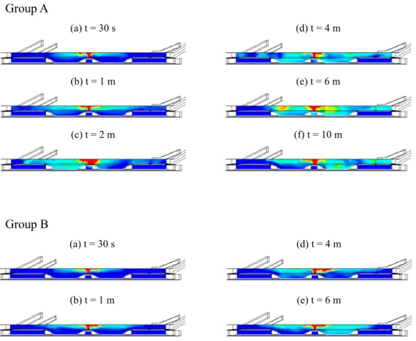
Figure 6 Effects of smoke control due to different smoke-control schemes. In all cases considered, the fire occurs on the center of the platform floor. In Group A, no smoke control system is engaged, the smoke is driven due to the stack effect and is propagating to the right of station. In Group B, the SEG is on, the stack effect is suppressed by the suction of SEG, rendering the smoke stay in the central part of station. In Group C, the TVF and UPE are active, a great majority of smoke is evacuated through the tunnels due to TVF while a minority of smoke is evacuated through the openings of UPE, leaving a small part of smoke in the central part of station. Group D shows clearly at t = 1m that (a) only a small part of smoke stays in the station and (b) a strong stream of smoke passes through the tunnels due to TVF.
Group A (a) t = 30 s (d) t = 4 m (b) t = 1 m (e) t = 6 m (c) t = 2 m (f) t = 10 m Group B (a) t = 30 s (d) t = 4 m (b) t = 1 m (e) t = 6 m
(c) t = 2 m (f) t = 10 m
Group C
(a) t = 30 s (d) t = 4 m
(b) t = 1 m (see Group D) (e) t = 6 m
(c) t = 2 m (f) t = 10 m
Group D
(a)
Figure 7 Velocity vectors in different cross sectional planes at t = 6m. The fire occurs on the center of the platform floor, all TVF, UPE and SEG are active. (a) The HCS plane is two meters above the platform floor. Due to the strong suction of TVF, the flow velocities in the four tunnels are as high as 5m/s, and so are the flows in the vicinity of the two escalators moving down from lobby floor to platform floor. (b) The HCS plane is two meters below the ceiling. Strong streams of fresh air move through the four Exits into station. (c) The VCS plane is on the center of the left lobby. Strong streams of fresh air move in the left lobby. (d) The VCS plane is on the center of the right lobby. Strong stream of fresh air moves through Exit D into station.
(a)
(c)
(d)
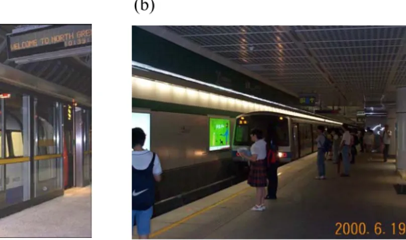
Figure 8 (a) The PED of a subway station in the Jubilee line of London subway system. (b) The platform floor of GGSS without PED.
(a) (b)
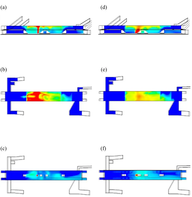
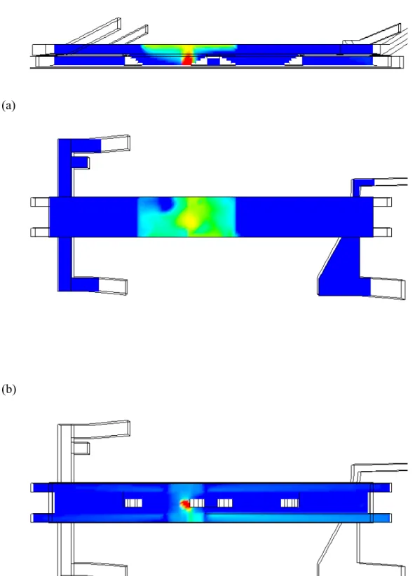
Figure 9 A comparison between the smoke distributions in GGSS with and without PED. The fire occurs on the center of platform, all the smoke control schemes TVF, UPE and SEG are active. Sub-figures (a), (b) and (c) are the smoke distributions at t = 40sec on the VCS plane at the middle of station, on the HCS plane one meter below the ceiling, and on the HCS plane two meters above the platform floor, respectively; all are for the case without PED. Sub-figure (d), (e) and (f) are for the same cross sectional planes while with PED, where all the doors are opened so that the smoke can be sucked into the tunnels through the doors by TVF. Sub-figure (f) shows clearly that the smoke pass through each door due to TVF.
(a) (d)
(b) (e) (c) (f)
Figure 10 Smoke flow in GGSS at t = 40sec when only 8 selected doors near the fire are opened. The fire occurs near the center of the platform floor, all TVF, UPE and SEG are active. (a) The smoke distribution on the VCS plane at the middle of station. (b) The smoke distribution on the HCS plane one meter below the ceiling. (c) The smoke distribution on the HCS plane two meters above the platform floor. (d) The velocity vectors corresponding to (c).
(a)
(c)
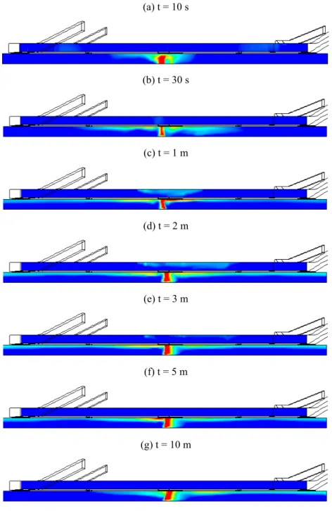
Figure 11 Smoke propagation in GGSS with PED when fire occurs on the chasses of the central wagon of train. The VCS plane locates 0.25 meter from the wall of tunnel. It is seen that the smoke moves along the ceiling of tunnel, being sucked into tunnels by the TVF at the two sides of station.
(a) t = 10 s (b) t = 30 s (c) t = 1 m (d) t = 2 m (e) t = 3 m (f) t = 5 m (g) t = 10 m
Figure 12 The same case with Fig. 11, the HCS plane locates two meters above the platform floor. The smoke is well restricted in the tunnel space, due both to the suction of TVF and the existence of PED.
(a) t = 10 s (e) t = 3 m
(b) t = 30 s (f) t = 5 m
(c) t = 1 m (g) t = 10 m
Figure 13 The same case with Fig. 11, the VCS plane cut through the center of the wagon on fire. All the doors of PED and train are opened to evacuate passengers. It is seen that only a small part of smoke moves into station.
(a) t = 10 s (g) t = 3 m
(b) t = 30 s (h) t = 5 m
(c) t = 1 m (i) t = 10 m
Figure 14 A comparison case to Fig. 13 while without PED. A large amount of smoke moves into station, the suction of TVF is not so effective as that of Fig. 13.
(a) t = 10 s (g) t = 3 m
(b) t = 30 s (h) t = 5 m
(c) t = 1 m (i) t = 10 m
PART II: THE EVALUATION RESEARCH OF EVACUATION SAFETY IN TAIPEI TRTS UNDERGROUND STATION
1. INTRODUCTION
Due to its specific spaces and complexes in usages and management, the underground MRT station does not accommodate to regular fire-safety regulations in Taiwan. TRTS adopts NFPA (National Fire Protection Association) 130 as the design criteria, evacuating all the passengers in a platform floor within 4mins and those in a station within 6mins, for evacuation safety. The Prescriptive Code, NFPA130, proposes fixed parameters and a simplified available safety egress time, which cannot reasonably describe the evacuation process and adjust the parameters for the real fire scenarios. Thus, to hold a full-scale maneuver of evacuation, due to a huge cost trial, does not match the principle of economic efficiency. Therefore, to adopt the computer simulation approach, an appropriate alternative, can raise the reasonability and feasibility in the evacuation research. Simultaneously, its results can be used to check the safety of specific architectural spaces and to persuade officers and clients for reaching the goals of saving cost and encouraging creative designs.
In order to construct a more complete evaluation structure for evaluating the egress safety of an underground station, this paper took HDSS as an example and utilized the buildingEXODUS software as an analytic tool for evacuation safety analysis. Those results can be the strategies proposed to TRTS in emergency response management.
2. VERIFICATION OF BUILDINGEXODUS COMPUTER SIMULATION
2.1 Verification and Application of EXODUS
buildingEXODUS is designed for applications in the built environment including supermarkets, hospitals, rail stations, airport terminals, high rise buildings, and so on.
It can be used to demonstrate compliance with building codes, to evaluate the evacuation capabilities of all types of structures and to investigate population movement efficiencies within structures. It also takes into consideration for people-people, people-fire and people-structure interactions. This model tracks the paths of individuals as they make their way out of the enclosure, or are overcome by fire hazards such as heat, smoke and toxic gases. Thus, the behavior and movement of each individual is determined by a set of heuristics or rules. For additional flexibility these rules have been categorized into five interacting sub-models, OCCUPANT, MOVEMENT, BEHAVIOR, TOXICITY and HAZARD [1]. Above all, the results can be the important references for simulating evacuation time when fire occurs. There are several verification and application as following:
I. In Paulsen’s research [2], the experimental evacuation time for the 1.5m exit is quoted as 30 seconds. This is apparently for a single trial. Five repeat runs of buildEXODUS produced evacuation time of 28.8, 29.1, 29.6, 31.1 and 31.4 seconds with a mean time of 30 second, resulting in a difference of 0%.
II. In Taiwan, the Graduate School of Fire Science, Central Police University applied buildingEXODUS to simulate the evacuation in underground MRT stations Ching-Mei [3] and Gung-Guan [4].
2.2 Functional Analysis of EXODUS
buildingEXODUS provides some measures to examine the outputs, which can be used to prove its reality. Two measures for evacuation efficiency are given as following [5]:
I.Optimal Performance Statistic (OPS)
OPS is measured from 0.0 to 1.0, a lower value indicating a more efficient evacuation. OPS is defined by the equation:
1 ( ) OPS= ( 1) n i i TET EET n TET = − − ×
∑
(1)n = number of exits used in evacuation
EETn = Exit Evacuation Time (time last passenger out) of Exit n (seconds)
TET = Total Evacuation Time (seconds) = max[EET]
An OPS value of 0 signifies a well-balanced evacuation, i.e. all exits completing at the same time, while an OPS value of 1.0 indicates a poor evacuation with at least one exit not attracting any occupants. Though the OPS is a useful measure of optimal performance, it only provides performance information at a time point, i.e. at the end of the evacuation. As such, it provides no insight into how the evacuation has progressed. To overcome this deficiency another measure has been developed to complement OPS, which is known as the Mean Non-flow Statistic or MNS.
II. Mean Non-flow Statistics (MNS)
The MNS provides a measure of the amount of time that each exit is not in use during an evacuation, i.e. no person negotiating the exit. The MNS can be determined from every exit and used as a measure of overall evacuation efficiency. The formulation of the MNS for an exit is as follows:
= i i i TNF MNS TFT ( 2 )
MNSi = Mean non-flow time for exit “i”
TNFi = total time (seconds) exit “i” is in non-flow conditions, i.e. no person negotiating the exit
EETi = time last person leaves exit “i” EFTi = time first person leaves exit “i”
The formulation of MNS for a building is as follows:
1 MNS = n i i MNS n =
∑
ٛ (3)MNS is the mean non-flow time for the building, and n is the number of exits during the evacuation. The MNS must be less than 100%. An evacuation in which MNS = 0 indicates that all the exits achieved a continuous evacuation flow without a breakdown. Generally, we consider MNS values less than or equal to 10.0% as being optimal. Above all, an ideal evacuation would have OPS = 0.0 and MNS = 0.0.
3. CONSTRUCTING THE PARAMETERS OF HDSS
Through buildingEXODUS, this paper simulated the evacuation in the platform floor of HDSS. The parameters are described as follows:
3.1 Architectural Characteristics of Platform Floor of HDSS
The length of platform floor is 141m and the width is 11.9m. In that area, two 1.8m width emergency exits at two ends of the floor connect ground floor and platform by stairwells. Three escalators, of which the width is 1.2m, one stair, of which the width is 1.8m, and one elevator (not for the purpose of evacuation), connect the lobby floor and the platform.
To draw the plans of HDSS on AUTOCAD DXF format is imported to the Geometry Mode of buildingEXODUS. Simultaneously, the Tools menu convert the DXF file to two-dimensional grid of nodes, such as Node, Arc, Seat Nodes, Internal Compartments, Obstacles and External Exits, and so on. Before constructing
staircases, the user has to key in the related values to define the size of the staircases. In staircase dialogue box, the values must be adjusted appropriately, such as the Width, Drop, Lane Width (default value- 0.76m) and advances data – Hand Rails, Riser High and Riser Depth. In this project, the Land Width is adjusted to TRTS default value – 0.56m. The plan of Hsing-Dein Subway Station is illustrated on Fig. 1, in which Exit5 ~ Exit8 mean one stair and three escalators.
Fig. 1. The Plan of Hsing-Dein Subway Station (HDDSS)
The number of the evacuation occupants was based on those predicted by Department of Transit System, Taipei City Government during the rush hours [6]. According to the scenario on the TRTS design and planning handbook 12th Edition [7], the total number of occupants – 2731 was estimated in this paper. The occupant number was obtained from a train with 1900 passengers and 1.5 times of the number of occupants entering the station. Through Population Panel Editor (PPE), 2731 occupants were randomly distributed on the platform floor. Their response times were among 0 – 30 seconds. The individual attributes of genders and ages were adopted from the questionnaires for TRTS passengers, research results of The Graduate School of Traffic Management, Central Police University [8].
3.3 Defining A Scenario
Because there are more than two stairs or escalators on the platform floor, Attractor and Discharge nodes are used to control the Exit Attractiveness for occupants. For the HDSS simulation, the Patience Attribute Value, 1~5 seconds, were adopted; the Unit Flow Rate default value – 1.33 occupant/m/sec was used. Exit
Status (default – Open) and Exit Activity (default – Yes)
were also adopted. When set to OPEN, any occupant queuing may pass through. If the active attribute is YES, occupants will be attracted to the exit and queue, even if it is closed. In additional, all Exit Potential and Exit Attractiveness (default value – 100) were used to simulate the evacuation.
3.4 Executing A Simulation
Before executing the HDSS simulation, the user adjusted in advance the
occupant behavior settings, which are separated into Behavior, Awareness and Environmental Response, from the Occupants Options in Rule Base Menu.
4. SIMULATION AND ANALYSIS OF HDSS
4.1 Executing Evacuation Simulation for HDSS
This simulation firstly was based on the default values of buildingEXODUS. Then the exit potential and attractiveness nodes, occupant attributes and awareness etc., were also adjusted for simulating the real evacuation scenarios. The summary of evacuation simulation in HDSS is described as Tab. 1.
Tab. 1. Analysis of buildingEXODUS Evacuation Simulation in HDSS
Simulati
on Setting Scenario
Exit
Evacuation Time (second)
OPS Result Analysis
1st
1. Lane Width = 0.56m
2. 2731 occupants were randomly distributed on the platform floor.
670.50 0.612
1. MNS ≠ 0 but > 0.1
2. Potential influenced the Exit Attractiveness for passengers.
2nd
1. UFR = 1.27 occ/m/s 2. Extreme Behavior Mode 3. Packed Behavior on Staircase 4. Exit Potential was adjusted. 5. The options of Impatient, Instant
312.82 0.282
1. MNS = 0 2. OPS>0.1
3. The last passenger stayed at Exit 8.
Response and Seat Jumping were selected.
3rd
1. As the conditions of the 2ndtime.
2. Each Exit Potential was adjusted
to better evacuation mode. 247.99 0.080
1. MNS = 0 2. OPS<0.1
3. The scenario close to the evacuation mode of ensuring passengers safety.
4th
1. Occupant Response Time = 0 sec 2. Travel Speed = 1 m/sec
3. Exit 8 was closed.
4. Each Exit Potential was adjust to help for evacuation
290.50 0.109
1. OPS>0.1
2. This scenario was the same with that of TRTS.
3. The Exit Evacuation Time was closer to the real condition than that of TRTS.
5th
1. Emergency Staircases were just for the purpose of emergency evacuation.
2. Exit Attractiveness = 50﹪ 3. Most passengers were waiting for train on the platform floor during rush hours.
284.32 0.078
1. The data of evacuation time can be the reference of operation management.
4.2 Simulation Analysis
When a hazard occurs, each aspect of management, including the occupant evacuation and emergency response, should cooperate each other to reach the standard of evacuation safety. The different occupant numbers of every exit in 5 time simulations were described as Tab. 2. In addition, the evacuation plan was verified by the 3rd and the 5th times.
Tab. 2. Occupant numbers using various exits
xit1 xit2 xit3 xit4 xit5 xit6 xit7 xit8
1st 87 27 82 86 12 74 45 18 2nd 54 47 83 81 78 79 60 49 3rd 30 05 77 51 05 44 11 08 4th 33 22 93 71 95 65 52 5th 52 32 40 70 34 95 08
I. The 3rd simulation demonstrated that most passengers evacuate from emergency exits more than those from stairs and escalators because every emergency exit has larger capacities of evacuation. From this simulation, the exit evacuation time can be reduced if occupants choose the emergency exits to evacuate. As a result, installing the voice broadcast systems for guiding evacuation at emergency stairwells is suggested, and those systems can be switched in the operation center or the control room of subway station. This purpose is for letting the passengers know which way they can choose to evacuate during the initial period.
II. From the occupant numbers of using stairs and escalators, the occupants using Exit 7 and Exit 8 are more than those using Exit 5 and Exit 6. For this reason, to guide the occupants at the central area of the platform floor to evacuate form Exit 5 and Exit 6 can get better evacuation efficiency.
III. From the result of the 3rd simulation, setting monitors to provide the information of occupant numbers at each exit in operation center is proposed. IV. In the 5th simulation, people using the southe exits of the platform-
Emergency Exit 1, Emergency Exit 2, Exit 5 and Exit 6, were less than those using north exits. Therefore, to guide more passengers to evacuate from the south exits in initial period becomes the goal of emergency response.
5. CONCLUSIONS
I. Through the observation of inappropriate or unreasonable evacuation routes in the process of simulation, the packed or staggered behaviors on staircases can be avoided by adjusting the Exit Potential and Exit Attractiveness. Therefore, the awareness and the ability of selecting exits are the key factors of evacuation safety and can also complement the inadequacy of prescriptive-based codes.
II. buildingEXODUS computer simulation provides various parameters, such as Awareness, Environmental Response and Patience, influencing the evacuation processes. The consideration of these variables will make the simulations be closer to real conditions than that of TRTS.
III. All results and related parameters from the buildingEXODUS can become the references of emergency response and safety strategies of TRTS.
IV. Efficient evacuation relies on the planning of evacuation guide for staff organization. Hence, to edit the evacuation safety handbook, to reinforce the
abilities of emergency response and to drill for staff become important in disaster protection.
V. Most passengers are unfamiliar with the emergency exits because the emergency exits are set at the ends of platform floor. The information of emergency evacuation routes should be provided to passengers by means of monitors, broadcast or post.
REFERENCES
[1] E.R. Galea, S. Gwynne, P.J. Lawrence, L. Filippidis and D. Blackshields, “buildingEXODUS V3.0 User Guide and Technical Manual,” Fire Safety Engineering Group, University of Greenwich, UK, p.2.1, 2000.
[2] Paulsen, T., Soma, H., Schneider, V., Wiklund J. and Lovas, G., “Evaluation of Simulation Models of Evacuation from Complex Spaces,” SINTEF REPORT, STF75 A95020, ISBN 82-595-8583-9, 1995.
[3] J. Y. Wu, “Using EXODUS Evacuation Software to Proceed the Calculation of Required Safe Egress Time –Taking Underground Station as An Example,” Master thesis, Central Police University, Taiwan, pp.97-125, 2000.
[4] C. C. Cheng, “A Study on the People Evacuation Safety for the Underground Rapid Transit Station,” Master thesis, Central Police University, Taiwan, pp.128-143, 2001.
[5] E.R. Galea, S. Gwynne, P.J. Lawrence, L. Filippidis and D. Blackshields, “building EXODUS V3.0 User Guide and Technical Manual,” Fire Safety Engineering Group, University of Greenwich, UK, pp.7.32-7.34, 2000.
[6] Engineering Inspect Squad of Rapid Transit Systems, ”An Engineering Investigation Report of TRTS Hsing-Dein Line South Section,” Department of Rapid Transit Systems, Taipei City Government, p14, 1999.