Design and Analysis of Accelerative Preallocation
Protocol for WDM Star-Coupled Networks
Chuan-Ching Sue and Sy-Yen Kuo, Fellow, IEEE
Abstract—For a wavelength division multiaccess (WDMA)
system, the reservation (R-WDMA) and the preallocation (P-WDMA) protocols are two major media access methods to support packet-switched traffic. In this paper, a new media ac-cess control (MAC) protocol, accelerative preallocation WDMA (AP-WDMA), is proposed to overcome the disadvantages of P-WDMA and retain its advantages. AP-WDMA relieves the tech-nology constraints by restricting the wavelength tunability at only one end of the communication link, removes the channel and station status tables required by R-WDMA, and uses simple arithmetics to allocate channels. Although it uses a dedicated control channel to send control–acknowledge packets, AP-WDMA employs a network management mechanism to make full use of idle time slots under different propagation and tuning delays. In addition, it is well suited to wavelength-limited networks. Three heuristic methods for channel sharing, interleaved (I), neighborhood (N), and weighted-balanced (WBH), are evaluated. Through analytical evaluations, AP-WDMA is shown to be able to improve the channel utilization and system throughput much more significantly than I-TDMA , which is a P-WDMA protocol. We also evaluate the impact on the performance of AP-WDMA by the number of chan-nels, the four traffic types (mesh, disconnected, ring, and uniform), the degree of channel sharing, and the unbalanced load among channels. The results show that the utilization is scalable in terms of the number of channels. Furthermore, the utilization of channels is best for the ring-traffic type and worst for the disconnected-traffic type, and the system throughput decreases as the degree of channel sharing increases. Finally, using heuristics I or WBH instead of N can resolve the unbalanced load problem under various traffic types and degrees of channel sharing.
Index Terms—Channel sharing, media access protocols, optical
networks, wavelength division multiplexing (WDM).
I. INTRODUCTION
F
OR the past decade, optical technology has been used widely in high-speed long distance communications and local area networks (LANs) [1]–[3]. For general application, wavelength division multiplexing (WDM) [4]–[10] is the most popular and efficient technology investigated, so far, that utilizes the very high data rate and vast bandwidth provided by an optical fiber.The reservation (R-WDMA) and the preallocation protocols (P-WDMA) are two main media access methods developed for this purpose [11]–[17], [20]–[24]. P-WDMA [12], [15], [16], [20]–[22], [24] has lower implementation and operation com-plexity, and R-WDMA [11], [13], [14], [17], [23] has worse Manuscript received January 25, 2001; revised November 26, 2001. This work was supported by the National Science Council, Taiwan, R.O.C., under Grant NSC 89-2213-E002-114.
The authors are with the Department of Electrical Engineering, National Taiwan University, Taipei, Taiwan (e-mail: [email protected]).
Publisher Item Identifier S 0733-8724(02)01476-7.
performance because a large number of collisions and retrans-missions can occur if many stations request the same data or control channel simultaneously, especially in a high-load en-vironment. Although several approaches were proposed to im-prove the performance of R-WDMA [13], [17], they only illus-trate the application of the protocols on specific WDM archi-tectures with constraints such as tunability and large tables. Al-though the approach in [11], [14] used two phases, reservation and transmission, to avoid the use of a control channel, the prop-agation and tuning delays incurred in the reservation phase may have big impact on performance. Sivaraman and Rouskas also proposed a look-ahead mechanism without a control channel to collect the status of buffers on data channels for generating a P-WDMA-like schedule [23]. However, this mechanism must check the packet type and will not be useful if the propaga-tion and tuning delays are negligible. Furthermore, P-WDMA is not always efficient because, first, if the traffic is not uni-form in a network, some stations and channels may remain idle while others wait for appropriate time slots, causing large de-lays. Second, if a source wants to transmit data right after a prescheduled time slot in which it can communicate with its destination, it must wait until the next prescheduled time slot for transmission. In either case, the network will have lower channel utilization, lower throughput, and higher delay.
Although several P-WDMA protocols were proposed in [20], [21], [24] under the constraints of tuning, processing, or prop-agation delays, they all assumed that the traffic load is fixed and known in advance so that they can schedule the transmis-sion better. In realistic situations, the traffic load changes be-tween uniform and nonuniform, as well as high and low. In ad-dition, each station in those approaches uses a large table to store the time-wavelength-station schedule, rather than simple arith-metics to derive the cyclic schedule, as the P-WDMA in [15], [16], [22].
In this paper, the AP-WDMA, which is based on P-WDMA and the methods in [25], [26], is proposed. To make a station simple, a cyclic P-WDMA is preferred because the frame size in a cycle is fixed to save the memory space for maintaining the schedule. To overcome the drawbacks of P-WDMA without adding too much cost, AP-WDMA allocates a small time slot in the control channel to perform the control and acknowledg-ment. The protocol enables a source station to possibly transmit the data earlier than the prescheduled time slot using the simple control–acknowledgment information in the control channel. AP-WDMA takes advantage of such early transmissions to speed up the overall data transmission. Only a small fraction of the control channel capacity is needed, and the remaining capacity can be used for other purposes, such as network 0733-8724/02$17.00 © 2002 IEEE
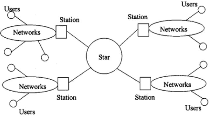
Fig. 1. Example FTTR-S with several users per station.
management and system synchronization. Even if early trans-missions cannot be achieved in some cases, AP-WDMA still performs better than P-WDMA. Thus, it retains the advantages of P-WDMA and improves the performance of P-WDMA. Furthermore, AP-WDMA works well in a wavelength-limited network, where the number of wavelengths is smaller than the number of stations, by channel sharing mechanisms. Only additional memory spaces for storing the identifications of the corresponding source stations are necessary in each station for making acknowledgment decision, where is the number of stations in the network.
The rest of this paper is organized as follows. In Section II, we define the architecture considered in this paper. The media access protocol, AP-WDMA, is proposed in Section III. Sec-tion IV presents the analytical evaluaSec-tions and results. Finally, we conclude our study in Section V.
II. ARCHITECTURE
In this section, we will illustrate the architecture for AP-WDMA. The concept of AP-WDMA can be applied to any WDMA system that has either tunable transmitters or tunable receivers but not both, and the number of channels is less than or equal to the number of stations. In this paper, only the basic architecture is considered, for clearer presentation without loss of generality. The basic architecture is the fixed-transmission tunable-reception passive star (FTTR-S) architecture, which is a single-hop broadcast-and-select photonic network built based on a passive star coupler, as shown in Fig. 1. A station, which is an optical-electronic converting module using WDM components, is connected with a single user or a cluster of users, whereas a user is a set of electronic components. Users can be interconnected based on any network topology and use the same wavelength for communication at the same time slot with a collision-avoidance protocol. In addition, AP-WDMA focuses on the media access layer between any two stations. Therefore, the single-hop accessibility means that no interme-diate retransmission is needed between any two stations.
Let be the control channel for the transmission of control
and acknowledgment (ACK) packets, and each , ,
represents a data channel for data transmission. , , , and are the available wavelengths in a system. The passive star coupler connects stations in the system. Assume , limited by the current technology. Stations are numbered from
Fig. 2. The architecture of a station. F-Tx: fixed-tuned transmitter. F-Rx: fixed-tuned receiver. T-Rx: tunable receiver.
to . Wavelength is
as-signed to the transmitter of station as its home channel, . A group of stations with the same home channel
is identified as station : . For the
trans-mission function, each station is provided with two fixed-tuned transmitters to avoid frequent tuning. One is fixed at for con-trolling and acknowledging early transmission and the other is fixed at its home channel for data transmission. For the re-ception function, each station is equipped with one fixed-tuned receiver and one tunable receiver to avoid frequent tuning. The fixed-tuned receiver is also fixed at to receive the control and ACK packets, whereas the tunable receiver can switch to any data channel for data reception. The architecture of each station is shown in Fig. 2. Some elements not shown in Fig. 2 are intro-duced here. First, each station has additional single-packet buffers with one buffer for the packets to a specific destination. Packets arriving at a full buffer are lost. It should be emphasized that this is a model of the media access control (MAC) layer [20]. Packets that cannot be buffered at the MAC layer are not actually lost and are typically buffered at a higher layer. Second, every station should reserve memory spaces, each with size , to determine the destination identification of the ACK packet in the AP-WDMA if the system is a wavelength-limited network. On the other hand, if , only one memory space, instead of memory spaces, is required to generate the proper ACK packet.
III. MEDIAACCESSPROTOCOL
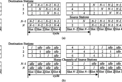
In this section, AP-WDMA is proposed based on the assump-tions in [25], [26]. Fig. 3 shows the allocation map for data channels in AP-WDMA. Fig. 3(a) shows an example allocation map for . Each station has a slot reserved for it on each channel (other than its home channel) during every cycle. In this case, the cycle has a length of slots, assuming that a sta-tion will not be required to transmit to itself. Fig. 3(b) shows another allocation map for . The cycle has a length of slots because stations in can transmit to station . A station is assigned a total of slots per cycle and remains idle for the remaining slots. In addition to the preallocation map for data channels, AP-WDMA further utilizes a control channel to broadcast the control packets and ACK packets. The informa-tion in the control channel is known to all stainforma-tions in the
net-Fig. 3. Preallocation map for data channels. (a)N = C. (b) N > C.
Fig. 4. The AP-WDMA protocol.
work in order to allow early transmissions. Fig. 4 shows the AP-WDMA protocol, which will be detailed in the following five subsections.
A. Control Packet Transmission
While the data are being transmitted concurrently in a data slot, the procedure Control_cycle( ) is performed on each station in order to transmit the control packet. It is based on two poli-cies. First, the time-interleaved preallocation is used such that, in every control cycle, the th control slot is used only by station to transmit the control packet. Second, at the th control slot, whether station will transmit a control packet or not is deter-mined by the check-and-send policy. The first rule is to prevent collisions. The check-and-send policy determines the behavior of control packet transmission at the th control slot based on the following cases.
Case 1) If station has no data for any other station in the one-packet buffers after this data slot, station remains idle.
Case 2) If the buffer for the preallocated destination station is not empty, station transmits the control packet
Fig. 5. The reception information in each station. (a)N = C. (b) N > C.
containing the identification number of station as the address bits.
Case 3) If neither of these circumstances occurs, an early transmission is possible at the next data slot. Station will transmit the control packet whose address bits indicate the idenfication number of the earliest next possible preallocated destination.
In the control cycle, each station uses an equation to derive the numer of the preallocated destination. This can be easily ob-served in Fig. 3. This preallocation information is established based on the time-channel source-destination station relation-ship. It illustrates that, for every data cycle, each is used as the receiving wavelength one by one by each station . The resulting scenario is that, for every data cycle, only the desti-nation can receive the data from the source on channel
at slot with if . If
, source station is preallocated at slot to transmit the data on channel to destination station where
.
B. ACK Packet Transmission
After executing the Control_cycle( ), the protocol performs the following steps to establish the transmission. If station finds no control packet during this control cycle (actually, all sta-tions should have the same information), it illustrates that there will be no transmission in the next data slot. No ACK packet is transmitted by station . Otherwise, the procedure ACK_cycle( ) is performed by each station . In the first part of ACK_cycle( ), the source identification number of the possible transmission is determined by the check-and-discard policy.
Fig. 5(a) shows the relationship between time, destination stations, and source stations for . It illustrates that, for every data cycle, destination is preallocated to receive the data on channel from source station at slot with
. Fig. 5(b) demonstrates that, for , at slot , destination is preallocated to receive the data on channel from source station at slot with
. If , the corresponding
receiver in station is kept idle because the station knows that no preallocation is possible in this data slot. Furthermore, the slot
ordering in a cycle can also be derived. If , destination is preallocated to receive the data from source on channel
at slot , with . If ,
destination is preallocated to receive the data from source on
channel at slot , with .
All of the received control packets are checked one by one as they are transmitted in Control_cycle( ). The steps can be
illus-trated for two cases, and . In the case of ,
for each control packet, the source identification number (rep-resented as ) of the first control packet destined to station is stored in the memory space of station . The source iden-tification number (represented as ) of each following control packet destined to station is compared with . If station is scheduled earlier than station in the next data slots, replaces in the memory space. Otherwise, the new incoming control packet is discarded. Therefore, after one control cycle, the source identification number of the possible unique source station is selected for station . In the case of , for each control packet, the source identification number, represented as , of the first control packet destined to station is stored in the corresponding memory space of station . The source iden-tification number, represented as , of each following control packet destined to the same station is compared with . If
and have the same home channel, i.e., ,
ran-domly select or . Otherwise, if is earlier than in the next data slots, then replaces in the memory space. Otherwise, the new incoming control packet for station is discarded. Therefore, after one control cycle, each memory space has a source identification number or nothing. The source identification number in the memory space forms a trans-mission pair and has a corresponding preallocated time slot. Sequentially compare the preallocated time slots of the trans-mission pair that have the same home channel identification number with the source identification number in the memory space , and choose the earliest one as the final unique trans-mission pair. The discarded one is cleared in the corresponding memory space.
The second part of ACK_cycle( ) is for ACK packet transmis-sion, according to the following policies. The time-interleaved preallocation is used such that the th ACK slot of each ACK cycle is prescheduled for station to transmit the ACK packet. At the th ACK slot, whether station can transmit the ACK packet or not is determined by the check-and-send policy based on the following steps. If station has no ACK for any other sta-tion during this ACK cycle, stasta-tion remains idle. Otherwise, station transmits the unique ACK packet with source identi-fication number (represented as ) in the memory space as the address bits to confirm the transmission from station to sta-tion . Hence, each source stasta-tion that has transmitted the con-trol packet destined to station in Control_cycle( ) needs only to look into the th ACK slot in the ACK cycle. In addition, while transmitting an ACK packet, station can prepare to tune its tunable receiver to the corresponding channel to reduce the tuning latency.
C. Operations on Each Station
In the beginning, the protocol performs the procedure
Initial_condition( ) for each station to restart the channel
utilization from the beginning of the prescheduled table. The
configuration of the network, e.g., , , is
set at this time. Then, for every data slot, transmission and reception on each station are based on the results of the ACK cycle. For AP-WDMA, each data packet does not have to indicate its source and destination addresses because the coordination is done in the control channel. The address is indicated by the authorized station, which can transmit and receive on this channel at each data slot in every data cycle. In addition, a station does not have to know all of the information in the entire preallocated map to correctly execute the protocol. Instead, only two points have to be known by each station. First, for data transmission, each source station must know the corresponding destination identification number at each data slot on the home channel of the source station. A source station will use the equation obtained from Fig. 3 to derive the destination station identification number. Second, for data reception, each destination must know the corresponding home channel identification number of source station at each data slot. The destination obtains this information from Fig. 5 based on the relationship between time, destination stations, and home channels of source stations. Therefore, in every data cycle, each station can take advantage of the above information to improve the channel utilization compared with the general P-WDMA.
D. Example
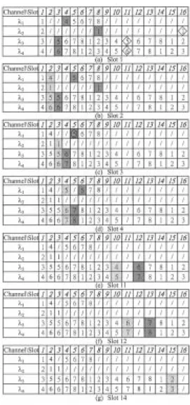
In order to illustrate the details of AP-WDMA, an example is provided in this subsection. This example is based on an FTTR-S that contains eight stations, one control channel, and four data channels. As illustrated in Fig. 6, the transmissions in two consecutive data cycles are considered.
The channel sharing information is {1, 2}, {3, 4}, {5, 6}, and {6, 7} are four groups in the system and their corresponding home channels are , , , and , respectively. The length of a data cycle, which is determined by the number of stations in the system, is eight. The acceleration achieved by the early transmission is shown in Fig. 6(a)–(g).
Fig. 6(a) shows the preallocation results by the P-WDMA, whereas Fig. 6(b)–(g) shows the process and results by the proposed AP-WDMA. In the figure, a slash represents an idle slot and an integer represents the preallocated reception station identification number. In Fig. 6(a), P-WDMA cannot utilize the idle slots and thus the channel utilization is low. AP-WDMA in Fig. 6(b)–(g) can utilize the idle slots by moving some preallocated slots earlier than originally scheduled and, thus, have higher channel utilization than P-WDMA. The detailed process is shown in Fig. 6(b)–(g) for time slots 2, 3, 4, 11, 12, and 14, respectively. For time slot 1 in Fig. 6(a),
when stations with home channels , , , and find
that the next prescheduled slots are idle, they look for next possible destinations by broadcasting a control message. They obtain ACK messages from destinations with identification numbers 4, 1, 5, and 6. These four destinations [shaded boxes in Fig. 6(a)] can be moved to slot 2 to receive data. The advanced destinations 1, 5, and 6 can be further replaced with the stations 1, 5, and 6, respectively, in diamond boxes of the next data cycle, as shown in Fig. 6(a) and (b). The original preallocated
Fig. 6. The transmission behavior of P-WDMA and AP-WDMA.
slot for the advanced destination 4 becomes idle because there is no packet for destination 4 in the next data cycle. Fig. 6(b) shows the result after time slot 1. The rescheduled destinations 4, 1, 5, and 6 are shown in light shadows, and the next possible destinations 5, 1, 5, and 6 are shown in dark shadows. In time slot 2, AP-WDMA runs in the same way as in time slot 1 but the stations with home channel cannot be scheduled to transmit to destination 5, even if the next possible preallocated destination is 5. To emphasize this fact, destination 5 is circled in Fig. 6(c). This is because the preallocated slot for stations with home channel to destination 5 is earlier than the preal-located slot for stations with home channel to destination 5. Progressing in the same way to time slot 14, the final schedule generated by AP-WDMA is obtained.
E. Why AP-WDMA
Theoretically, the length of a data slot is determined by , , , and . Here, is the packet processing time, is the corresponding idle time for a data packet smaller than the maximum size, is the individual offset time due to the specific transmission distance between the source and destina-tion stadestina-tions, and is the tuning time required for the corre-sponding receiver to be tuned to the scheduled data channel.
Fig. 7. The relationships between the control and data channels.
Technically, is determined by the tuning speed of the tunable wavelength filter that can only be tuned at a limited speed and in a limited wavelength range [18], [19]. Generally speaking, the tuning speed will be slower if the tuning range is wider. For ex-ample, the number of supported channels and the tuning speed are estimated respectively to be 128 channels and a few mil-liseconds for a Mach–Zehnder filter, 100 channels and 10 mi-croseconds for an acoustooptic transverse electric (TE)–trans-verse magnetic (TM) filter, 10 channels and a few nanoseconds for an electrooptic TE–TM filter, and one or two channels and one nanosecond for a distributed feedbac (DFB) filter. Mean-while, the length of a control–ACK cycle is determined by and . is the individual offset time due to the specific transmission distance between the source and destination sta-tions, and is the processing delay of the control packet. Be-cause all of the packets have the same size and the corresponding receiver always senses on , , and are not the factors. If the data rate per channel is assumed to be about 1 Gb/s, then (control packet size)/1 Gb/s bits/1 Gb/s 0.8 s, for
. Furthermore, (control packet size)/1 Gb/s bits/1 Gb/s 100 s with . In our protocol,
it is assumed that . Although the propagation
delay can be masked in the data channels, it must be in-corporated in the control channel to account for the effect that all stations must hold for a period of time until all stations in the network receive the control–ACK packets. Considering the propagation delay, the tuning delay, the data slot, and the control–ACK cycle, there are two ways, as shown in Fig. 7, to control the data channels.
Fig. 7(a) shows the first case when the propagation delay is so short that the control can be done immediately. Fig. 7(b) shows the second case when the propagation delay is large enough to make immediate control impossible and the control information in the control channel is used for the next data slot. Note that the tuning operation for receivers can be started later after the ACK cycle in both cases because, at that time, the receiver has already made the decision. For the utilization of the data slot, the second case is better than the first because the tuning delay in the second one can be masked by the
prop-agation delay after the ACK cycle. For the control information, the first case can be better than the second because the control information in the second one is delayed by one slot compared with the first one.
As WDM technologies and components continue to improve, the required switching time of the receiver will be further re-duced. AP-WDMA can still perform very well if the number of stations connected by the star coupler is selected to satisfy one of the two cases. However, because only a small fraction of the control channel capacity is needed for control–ACK packets, the remaining capacity can be used for other purposes, such as net-work management and system synchronization. Furthermore, because those stations with the same home channel will not be able to use idle slots on a different channel even when they will likely encounter busy slots on the assigned channel, AP-WDMA may seem to have limited flexibility. However, through proper wavelength assignments for transmitters, the above drawback can be eliminated. Thus, the necessary information can be sent during the idle time in the control channel. The idle time can be started after the ACK cycle in Fig. 7(a) or based on the large propagation delay in Fig. 7(b).
IV. EVALUATION
This section evaluates the performance of AP-WDMA. Section V-A illustrates the system complexity of the FTTR-S. Section V-B uses the probability analysis to evaluate the advantages of AP-WDMA.
A. System Complexity
The system complexity of the FTTR-S is analyzed as follows. 1) Evaluation on optical power budget (OPB) is not per-formed in this paper. This is because the OPB for an archi-tecture built based on the passive star couplers has already been evaluated in [3], [16] and all evaluations indicated low OPB requirement.
2) From the architectural point of view, the FTTR-S in AP-WDMA is the same as that in R-WDMA and differs from the FTTR-S in P-WDMA as explained here. First, in the AP-WDMA, each station contains one extra fixed-tuned transmitter, one extra fixed-tuned receiver, and the corresponding links. Second, the number of available channels in AP-WDMA is less than that in P-WDMA by one, due to the control channel. However, the additional cost of FTTR-S in AP-WDMA is not significant. Furthermore, our approach does not limit the number of stations to be less than the number of available channels by one because each channel can support more than one station.
3) Due to the rapid development in WDM technologies and WDM components, the FTTR-S will reduce the system complexity and provide an even better system perfor-mance because the number of supported channels is in-creased and the device tuning time is reduced.
4) The FTTR-S has the characteristics of scalability, modularity, and fault tolerance, as discussed in [16]. AP-WDMA will even have better technical availability
because the number of available wavelength channels does not limit the number of supported stations.
5) The concept of AP-WDMA should be utilized and im-plemented in many WDMA systems, such as the mul-ticasting WDMA, the multihop WDMA, and the WDM architectures built based on different network topologies. These will be our future works.
6) In addition, the concept can be applied in both the satel-lite system and the radiowave system because they vide many channels and because the media access pro-tocol is based on either the preallocation or the reservation method, and both are involved with frequent switching between channels.
B. Analytical Evaluation
The network operates in a slotted mode, i.e., all stations are synchronized to the slot boundaries. This subsection quantitatively evaluates the channel utilization and the system throughput that aggregates the utilization of channels at a data slot. Each station has single-packet buffers, one for the packets to each possible destination. Packets arriving at a full buffer are lost. However, packets that cannot be buffered at the MAC layer are not actually lost, but are typically buffered at a higher layer. Because the behavior of a channel in AP-WDMA is not independent of other channels, the assumption of single-packet buffer can make the analysis traceable. First, let be the probability that a new packet arrives at station during a slot, the probability that a packet arriving at station is
destined to station , and . Thus, characterizes
the arrival process from the higher layer to the single-packet buffer for station when the buffer is empty. [ ] is the matrix of external traffic in units of packets per slot. Balanced traffic is assumed and analyzed first. Thus, is the same across all the stations. Furthermore, the case that is analyzed first to observe the effect of AP-WDMA on the number of channels and the traffic type. The fixed transmitter of station is assigned channel as its home channel. The case that
, i.e., the unbalanced traffic, is analyzed later.
As discussed previously, time slots are cycled in frames of slots for . The distance in slots between the begin-ning of the slot that station is preallocated to transmit to station and the beginning of such a slot in the next or previous frame is denoted as . For convenience, let the destination stations for source station be listed as
where each , , represents the destination
station that will be scheduled slots earlier in AP-WDMA, and means that the corresponding preallocated slot is the original preallocated slot. Based on these conditions, let represent the probability of each corresponding case for a source–destination pair . Therefore,
because the probability that station has a packet for station , i.e., , at the beginning of the slot is equal to the probability that at least one packet for station arrives at station
This comes from the fact that there are no packets destined to during the previous slots. However, there are
packets destined to during the previous slots
and cannot receive any data on its preallocated channel. The last term means that there is no packet destined to during the previous slots on its preallocated channel. In
addition, the expression means ,
to include the wraparound effect. Note that if for , or should be incremented to the next value or the value following or based on the equation, because the cyclic preallocation map
with is not continuous. is as follows:
The first three terms of describe the probability that there are no packets destined to and during the previous and slots, respectively, and there is at least one packet destined to during the previous slots. The last two terms depict the situation that and cannot receive any data on its preallocated channels, respectively. Different from
, the probability in the fourth term represents that cannot receive any data on its preallocated channel. This in-cludes two cases, first, that no packet is destined to during the previous slots, and second, that at least one packet is destined to the previous stations for station when there is at least one packet destined to during the previous
slots. In general, we have
consists of three components:
1) the probability that there are no packets destined to
sta-tions between and ;
2) the probability that there is at least one packet destined to
station ;
3) the probability that there are no destination conflicts for station on other channels.
With , the channel utilization and
the system throughput in a data slot can be obtained as fol-lows (general P-WDMA is indicated as I-TDMA* [22]):
for I - TDMA*
for AP - WDMA
for I - TDMA*
for AP - WDMA.
is obtained by the summation of utilizations in the chan-nels. Utilization in each channel is determined by the suc-cessful packet transmission of station to all possible destina-tions per data slot. The probability of a successful packet trans-mission from station to station is or the summation
of with from 0 to for I-TDMA* or AP-WDMA,
respectively. is the average utilization of channels and can be obtained by averaging on .
If , several transmitters have to be assigned the same
wavelength and share a single channel , . We
use three heuristics for assigning stations to the limited number of channels. Station is allocated channel as its home channel. There are three heuristic methods, neighbor (N), interleaved (I), and weighted-balanced (WBH). For heuristic N, the
relation-ship between station and channel is . For
heuristic I, . For heuristic WBH, the relationship is determined by three steps.
Step 1) Sort station in decreasing order of . Initialize
, , and . Note
that sets are also sorted in decreasing order.
Step 2) Let and . Sort ,
, in decreasing order. Step 3) Repeat step 2) if .
Note that if for , heuristic I is equivalent
to heuristic WBH.
with is different from with in
four ways.
1) Time slots are cycled in frames of slots for . The distance in the number of slots between the beginning of the slot preallocated to stations with home channel to transmit to station and the beginning of same type of slot in the next or previous frame is denoted as .
2) New is defined as .
3) The third component in needs some modification because possible destination conflict is reduced due to the smaller number of channels.
4) If , the cyclic preallocation map is continuous, and the subscript in the equation needs no further attention if
Fig. 8. Channel utilization with the number of stations–channels= 8, 16, and 24.
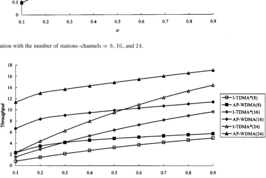
Fig. 9. System throughput with the number of stations–channels =8, 16, and 24.
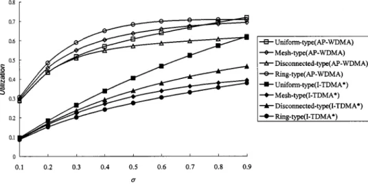
In the following, we will show the effect on channel uti-lization or system throughput of the proposed AP-WDMA for various numbers of channels, traffic types, degrees of channel sharing, and degrees of load balancing, and compare them with I-TDMA*.
1) Number of Channels: Uniform traffic type and balanced
load are assumed in Fig. 8 and 9. That is, the possible desti-nation for each source station is evenly distributed with
. Also, for each station is the same and denoted as . In Fig. 8, the channel utilization with different numbers of channels is shown for AP-WDMA and I-TDMA*. It can be concluded that AP-WDMA can always make the channel uti-lization higher than I-TDMA*. Furthermore, AP-WDMA can make the channel utilization higher as the number of channels increases, but I-TDMA* cannot take advantage of the larger number of channels to increase the channel utilization. How-ever, the increase in the channel utilization by AP-WDMA is not proportional to the increase in the number of channels. In fact, the increase in channel utilization saturates when the number of channels or increases over some threshold. In Fig. 9, we show the system throughput with different numbers of channels for AP-WDMA and I-TDMA*.
Due to the saturation effect in utilization, if is larger than the threshold 0.55 (0.3), a network of 24(16)-channels with I-TDMA* can generate higher throughput than a network of 16(8)-channels with AP-WDMA. On the other hand, if the system is operated with below the threshold 0.55 (0.3), it is possible that AP-WDMA can generate higher throughput than I-TDMA* with even fewer channels. The poor performance of I-TDMA* at low is due to the fact that it assigns exactly one slot per cycle to each source–destination pair without any early transmission. It can be concluded that a network with high utilization is not necessarily a network with high throughput. Although AP-WDMA can always make the channel utilization higher than I-TDMA*, it cannot fully show its advantage for higher . If a system can be operated with appropriate , its cost can be reduced with fewer channels, but its utilization is high. The increase of system throughput in AP-WDMA is more significant than that in I-TDMA* and is independent of , and the increase of system throughput in I-TDMA* is more significant for higher . The limitations of I-TDMA* and the potential for improvement by using AP-WDMA are depicted in Figs. 8 and 9 for larger networks. Thus, a system using AP-WDMA can be easily upgraded with more channels as the technology advances.
(a) (b)
(c) (d)
Fig. 10. Four different traffic types. (a) Uniform traffic. (b) Mesh-type traffic. (c) Disconnected-type traffic. (d) Ring-type traffic.
Fig. 11. Effect on channel utilization for four different traffic types withN = C = 8.
2) Traffic Type: We further consider the mesh-type,
discon-nected-type, and ring-type traffic matrices for eight stations, as shown in Fig. 10, including the uniform traffic matrix.
These traffic types are taken from [20]. Each entry ( ) in the matrices represent . We still let for all . This does not compromise the generality of our results, because the traffic characteristics are determined by . Fig. 11 shows the channel utilization results for four traffic types with .
It can be seen that the utilization (or throughput, because ) for AP-WDMA is better than that for I-TDMA* under the four traffic types. For AP-WDMA, a network with discon-nected-type traffic can make the utilization worse than that with uniform traffic and equal to the network using I-TDMA* with uniform traffic at . In addition, a network with mesh-type traffic has better utilization, and ring-type traffic the best utilization. When is increased to 0.9, the utilization for a network with uniform traffic is equal to that for ring traffic. As for I-TDMA*, it is consistent with our intuition
that a network with uniform traffic can perform better as increases. For ring-type traffic, more packets are destined to one specific destination station in each channel without conflict. Thus, AP-WDMA can generate significant speed up with early transmission technique. As for mesh-type or uniform traffic, AP-WDMA cannot always perform successful early transmission due to the destination conflict. Finally, for disconnected-type traffic, AP-WDMA performs worse because the destination conflict is more serious than other types of traffic.
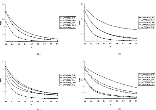
3) Degree of Channel Sharing: To clearly understand the
effect on the degree of channel sharing, we define the ratio as the utilization of I-TDMA* with the same number of channels divided by the utilization–throughput of AP-WDMA. Fig. 12 depicts the utilization–throughput ratio of AP-WDMA over I-TDMA* under four traffic types.
Heuristic method WBH for channel sharing is not shown in Fig. 12 because its result is the same as heuristic method I for
(a) (b)
(c) (d)
Fig. 12. The utilization–throughput ratio of AP-WDMA over I-TDMA* under four traffic types. (a) Uniform traffic. (b) Mesh-type traffic. (c) Disconnected-type traffic. (d) Ring-type traffic.
Fig. 13. Comparisons on channel utilization between the three heuristics under unbalanced load environment.
balanced load. It is seen that as the degree of channel sharing becomes higher, AP-WDMA has higher utilization–throughput than I-TDMA* since the ratio is always larger than 1 and is independent of . The advantage of AP-WDMA will disappear for higher because the probability of early transmission becomes smaller due to a larger number of preallocated trans-missions. The channel-sharing policy has no obvious effect on the ratio for all traffic types except the disconnected-type and ring-type traffic. In the disconnected-type traffic, heuristic
method N always performs better than heuristic method I. This does not follow our intuition that heuristic method N cannot change the traffic pattern even with channel sharing. This is because the corresponding I-TDMA* with heuristic method N performs even worse such that the ratio cannot really show the advantage of heuristic method I. For example, in ring-type traffic, heuristic method I performs better than heuristic method N. For uniform and mesh-type traffic, there is no significant difference between heuristic method N and
heuristic method I. Besides, for uniform and ring-type traffic, the ratio reduction is proportional to the degree of channel sharing. For disconnected-type traffic with heuristic method N, the reduction in ratio is not significant if the degree of channel sharing is low. For disconnected-type traffic and mesh-type traffic with heuristic method I, the reduction in ratio is signifi-cant if the degree of channel sharing is high. We can conclude that determining the degree of channel sharing depends on the traffic load and the traffic types.
4) Degree of Load Balancing: Parameter is defined to
pro-vide an upper bound on the load to be carried on any single channel. Specifically, no more than ( are carried on any given channel . In the previous evaluation, perfect load
bal-ancing is assumed with . Even if , can be
con-trolled if slow tunable, rather than fixed, transmitters are used in the network. Then, as the traffic pattern changes, the network can be reconfigured, i.e., stations may be assigned new home channels to keep the load evenly spread across all channels.
Fig. 13 uses an unbalanced load in an eight-station network
with for . The three heuristics, I, N,
and WBH, are compared for the channel utilization. In general, heuristic method WBH and heuristic method I are better than heuristic method N. Heuristic method WBH is a little better than heuristic method I for all the traffic types except ring-type traffic. When the load is unbalanced, heuristic method N is not favored for channel sharing. Although either WBH or I can be chosen for channel sharing, heuristic method I is preferred be-cause it has lower implementation complexity. As for network management, each station needs only send and as the control information to reflect the current traffic status for per-forming WBH, I, or N.
V. CONCLUSION
We have proposed a new MAC protocol, AP-WDMA, for WDM star-coupled networks. AP-WDMA is based on the P-WDMA without its drawbacks and improves the system performance with minimum cost. AP-WDMA allows a source station to transmit the data earlier than the preallocated time slot with the help of an additional control channel. Through examples and analytical evaluations, it has been shown that AP-WDMA improves both the channel utilization and the system throughput significantly for various numbers of chan-nels, traffic types, degrees of channel sharing, and degrees of load balancing. Furthermore, AP-WDMA can easily support various propagation delays and tuning delays. The idle time in the control channel is utilized by the network management to achieve higher channel utilization with three heurstics for load balancing. In addition, the proposed AP-WDMA is a practical media access control protocol without the need of maintaining the status and preallocated information because little control information needs to be sent on the control channel and the preallocation map is cyclic and fixed.
REFERENCES
[1] C. A. Brackett, A. S. Acampora, and J. Sweitzer et al., “A scalable multi-wavelength multihop optical network: A proposal for research on all-op-tical networks,” J. Lightwave Technol., vol. 11, pp. 736–753, June 1993.
[2] P. E. Green, L. A. Coldren, and K. M. Johnson et al., “All-optical packet-switched metropolitan-area network proposal,” J. Lightwave Technol., vol. 11, pp. 754–763, June 1993.
[3] C. A. Brackett, “Dense wavelength division multiplexing networks: Principles and applications,” IEEE J. Select. Areas Commun., vol. 8, pp. 948–964, Aug. 1990.
[4] A. Ganz and Y. Gao, “Time-wavelength assignment algorithms for high performance WDM star based systems,” IEEE Trans. Commun., vol. 42, pp. 1827–1836, Feb. 1994.
[5] S. T. Tan and D. Du, “Embedded unidirectional incomplete hypercubes for optical networks,” IEEE Trans. Commun., vol. 41, pp. 1284–1289, Sept. 1993.
[6] K. A. Williams, T. Q. Dam, and D. Du, “A media-access protocol for time and wavelength division multiplexed passive star networks,” IEEE
J. Select. Areas Commun., vol. 11, pp. 560–567, May 1993.
[7] J. Sasaki and N. Takato, “An optical multiaccessor designed for a fiber-optic star-ring LAN,” J. Lightwave Technol., vol. 10, pp. 250–254, Feb. 1992.
[8] G. N. Sudhakar, N. D. Georganas, and M. Kavehrad, “Slotted aloha and reservation aloha protocols for very high-speed optical fiber local area networks using passive star topology,” J. Lightwave Technol., vol. 9, pp. 1411–1422, Oct. 1991.
[9] M. S. Goodman, H. Kobrinski, and M. P. Vecchi et al., “The LAMB-DANET multiwavelength network: Architecture, applications, and demonstrations,” IEEE J. Select. Areas Commun., vol. 8, pp. 995–1004, Aug. 1990.
[10] M. S. Chen, N. R. Dono, and R. Ramaswami, “A media-access protocol for packet-switched wavelength division multiaccess metropolitan area networks,” IEEE J. Select. Areas Commun., vol. 8, pp. 1048–1057, Aug. 1990.
[11] P. W. Dowd, K. Bogineni, K. A. Aly, and J. A. Perreault et al., “Hier-archical scalable photonic architectures for high-performance processor interconnection,” IEEE Trans. Comput., vol. 42, pp. 1105–1120, Sept. 1993.
[12] K. Bogineni, K. M. Sivalingam, and P. W. Dowd, “Low complexity mul-tiple access protocols for wavelength-division mulmul-tiplexed photonic net-works,” IEEE J. Select. Areas Commun., vol. 11, pp. 590–604, May 1993.
[13] K. Bogineni and P. W. Dowd, “A collision-less multiple access protocol for a wavelength division multiplexed star-coupled configuration: Ar-chitecture and performance analysis,” J. Lightwave Technol., vol. 10, pp. 1688–1699, Nov. 1992.
[14] P. W. Dowd, “Wavelength division multiple access channel hyper-cube processor interconnection,” IEEE Trans. Comput., vol. 41, pp. 1223–1241, Oct. 1992.
[15] , “Random access protocols for high speed interprocessor commu-nication based on a passive star topology,” J. Lightwave Technol., vol. 9, pp. 799–808, June 1991.
[16] C.-K. Ko and S.-Y. Kuo, “Multiaccess processor interconnection using subcarrier and wavelength division multiplexing,” J. Lightwave
Technol., vol. 15, pp. 228–241, Feb. 1997.
[17] C. J. Hou, B. Wang, and C. C. Han, “Design and analysis of a WDMA protocol for passive star-coupled lightwave networks,” in Proc.
INFOCOM’96, Feb. 1996, pp. 1225–1233.
[18] J. P. Weber, B. Stoltz, and H. Sano et al., “An integratable polarization-independent tunable filter for WDM systems: The multigrating filter,”
J. Lightwave Technol., vol. 14, pp. 2719–2756, Dec. 1996..
[19] E. L. Wooten, R. L. Stone, E. W. Miles, and E. M. Bradley, “Rapidly tunable narrowband wavelength filter using LiNbO3 unbalanced Mach–Zehnder interferometer,” J. Lightwave Technol., vol. 14, pp. 2530–2536, Nov. 1996.
[20] G. N. Rouskas and M. H. Ammar, “Analysis and optimization of trans-mission schedules for single-hop WDM networks,” IEEE/ACM Trans.
Networking, vol. 3, pp. 211–221, Apr. 1995.
[21] F. Jia, B. Mukherjee, and J. Iness, “Scheduling variable-length mes-sages in a single-hop multichannel local lightwave network,” IEEE/ACM
Trans. Networking, vol. 3, pp. 477–488, Aug. 1995.
[22] P. W. Dowd and K. Bogineni, “TDM-based WDM access protocols: A comparison of reservation and pre-allocation strategies for a photonic star-coupled configuration,” Int. J. Comput. Simul., vol. 40, no. 1, pp. 21–40, 1994.
[23] V. Sivaraman and G. N. Rouskas, “HiPeR-l: A high performance reser-vation protocol with look-ahead for broadcast WDM networks,” in Proc.
INFOCOM’97, 1997, pp. 1270–1277.
[24] A. Dasylva and R. Srikant, “Optimal WDM schedules for optical star networks,” IEEE/ACM Trans. Networking, vol. 7, pp. 446–456, June 1999.
[25] C.-C. Sue, W.-Y. Tseng, and S.-Y. Kuo, “Architecture and analysis of accelerative pre-allocation protocol for WDM star-coupled networks,” in Proc. 1998 Int. Computer Symp., Dec. 1998, pp. 282–289. [26] C.-C. Sue, S.-Y. Kuo, and Y. Huang, “An accelerative pre-allocation
protocol for wavelength division multiplexing star-coupled networks,” in Proc. 1999 Int. Symp. Computers Communication, July 1999, pp. 209–215.
Chuan-Ching Sue was born in Kaohsiung, Taiwan,
on July 7, 1971. He received the B.S. and Ph.D. de-grees in electrical engineering from National Taiwan University, Taipei, Taiwan, in 1994 and 2001, respec-tively.
He is currently an information engineer at Navy Flight Command, Kaohsiung, Taiwan. His current research interests include fault-tolerant WDM net-works, high-speed computer netnet-works, and dis-tributed systems.
Sy-Yen Kuo (S’85–M’88–SM’98–F’01) received the
B.S. degree in electrical engineering from National Taiwan University, Taipei, Taiwan, in 1979, the M.S. degree in electrical and computer engineering from the University of California, Santa Barbara, in 1982, and the Ph.D. degree in computer science from the University of Illinois, Urbana-Champaign, in 1987.
He is currently a Professor and the Chairman of the Department of Electrical Engineering at National Taiwan University. From 1999 to 2000, he spent his sabbatical year as a Visiting Researcher at AT&T Laboratories Research, Florham Park, NJ. From 1995 to 1998, he was the Chairman of the Department of Computer Science and Information Engineering, National Dong Hwa University, Hualien, Taiwan. From 1988 to 1991, he was a faculty member in the Department of Electrical and Computer Engineering, University of Arizona, Tucson. In 1989, he also worked as a Summer Faculty Fellow at the Jet Propulsion Laboratory, California Institute of Technology, Pasadena. From 1982 to 1984, he was an engineer at Fairchild Semiconductor, Mountain View, CA, and Silvar-Lasco, Menlo Park, CA. His current research interests include mobile computing and networks, dependable distributed systems, software reliability, and optical WDM networks. He has published more than 160 papers in journals and conferences.
Dr. Kuo received the distinguished research award from the National Science Council, Taiwan, from 1997 to 2001. He received the Best Paper Award at the 1996 International Symposium on Software Reliability Engineering, and the Best Paper Award in the simulation and test category at the 1986 IEEE/ACM Design Automation Conference. He also received the National Science Founda-tion’s Research Initiation Award in 1989 and the IEEE/ACM Design Automa-tion Scholarship in 1990 and 1991.