CThX2
Fabrication and characterization of micro-structured
polymer optical fibers
C.-W. Huang,M.-C. Ho,C. P. Yu,H. C. Chang, and C. C. Yang
Graduore lnrtinile ofElecrm-Optiml Engineering rrndDeporrrnent ofElecrrica1 Engmeenng
Nohonol Towon Univeniry No. I , Sec. 4, RwseveltRd.. Taiper, 106, Toiww
H. H. Chien, K. J.
Ma,
and Z. P. ZhengDeporlmenl ofMechanica1 Engineering. Chung-Hun University No. 707. Sec. 2, WuFu Rd., Hsinchu. 307. Taiwrrn
Abstract: Single-mode micro-stmctured polymer optical fibers over the wavelength range of 633 through 1550 nm are fabricated and characterized. The effects of drawing temperature and beating time during the fabrication processes are studied.
02003 Optical Society of Ameican
OCIS codes: (060.2280) Fiber design arid fabricinion (250.54M)) Polymer waveguides-fibers
Recently, micro-strnctured optical polymer fibers (MPOFs) have attracted a lot of attention [1,2]. Compared to silica-based countelparts [3], MPOFs have advantages of better mechanical flexibility and considerable choices of material that can be used. In additioR MPOFs can in principle be fabricated at a much lower cost and novel fnnctionalities can possibly be explored with new materials. In this paper, we report the fabrication and characterization results of single-mode MPOFs over the range from 633 through 1550 nm The investigation results of the parameters that are critical in the fabrication processes of MPOFs are also discussed.
In fabricating the MPOFs, we wed the standard stack-and-draw technique. Hollow PMMA tubes ( ~ 1 . 4 9 2 ) with 4 mm outer diameter and 2 mm inner diameter were f m t stacked into a hexagonal array. Some hollow tube@) wadwere either replaced with solid rod@) or removed at selected site@) in order to form the fiber core. The stacked tubes were annealed at 110 "C for 3 hours for water removal and then heated to form the preform. The drawing of the MPOF is a two-step process. During the fmt step, the preform was drawn at an elevated temperatwe into a smaller preform with 40 cm in lenglh and 10 mm in diameter. This sinaller preform was then drawn again into a fiber with a diameter between 125 and 300 pm depending on the drawing temperature and speed. Before drawing, the MPOFs preform bas to be kept at the drawing temperature for a period of time, called diffusion treatment, in ordcr to achieve uniform temperature distribution across the whole MPOF preform. The drawing speed is controlled under 10 cdmnin. From the stacked tubes to a fiber, the overall scale of the strncture is reduced by a factor of 300.
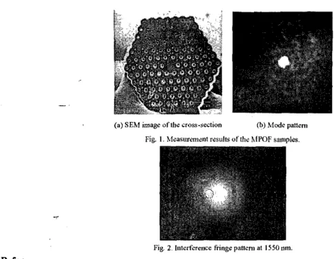
The fiber samples we conducted optical measwments were drawn at 175OC, with 1.5-hour diffusion treatment. The combination of these drawring parameters allow us to obtain moderate hole size, while the inlerstitial holes are almost eliminated. The light wurce we used to measwe the mode pattern is a 1550 nm DFB laser with standard single-mode fiber (SMF) pigtail. We butt-coupled the light from the SMF pigtail into the MPOF sample. The SEM image and the near-field mode pattern of one of the samples are shown in Fig. 1. It can be seen that the light is well-confned and guided in the core. To confum single-mode guiding we conducted interference experiment at 1550 nm. Fig. 2 shows the interference pattern between the guided mode and the input laser. The clear interference fringe in Fig. 2 confrms single-mode propagation [I]. The circle in Fig. 2 indicates the position of the guided mode. Similar interference fringe pattern were also observed when a HeNe laser was used for excitation, showing that the singlemode guiding property extends to 633 nm. We also measured the loss of the MPOF samples by the cut-back method. With this method, the loss of'the MPOF sample is estimated to be 88dBim at 1550 nm.
CThX2
Fig. 2. Iutcrfercnce Fringe pattern at I550 nm. References:
(I] hl. A. Eijkclenborg, h.1. C. 1. Large, et al., “hlicrostniclurcd polymer optical fibn,”OpficsErprers, 9,319-327(2001). [2] A. Argyros, 1. M. Bassen, el al. “Ring stmctines iii rnicrostmctured polymer optical fibres,” Oplicr Erpress, 9,813-820 (2001).
131 P. Russell, “Photonic crystal fiberj,”Science, 299,358-362 (2003).
141 J. K. Rank% R. S. Windeler, and A. J. Steniz, “Visible continuum generation in au-silica microstnrclure optical fiben with anomalous